Influence of the support on the physicochemical properties of Pt electrocatalysts: Comparison of catalysts supported on different carbon materials
Bạn đang xem bản rút gọn của tài liệu. Xem và tải ngay bản đầy đủ của tài liệu tại đây (1.92 MB, 7 trang )
Materials Chemistry and Physics 127 (2011) 335–341
Contents lists available at ScienceDirect
Materials Chemistry and Physics
journal homepage: www.elsevier.com/locate/matchemphys
Influence of the support on the physicochemical properties of Pt electrocatalysts:
Comparison of catalysts supported on different carbon materials
L. Calvillo, V. Celorrio, R. Moliner, M.J. Lázaro
∗
Instituto de Carboquímica (CSIC), Miguel Luesma Castán 4, 50018 Zaragoza, Spain
article info
Article history:
Received 11 March 2010
Received in revised form
15 December 2010
Accepted 8 February 2011
Keywords:
Mesoporous materials
Electrocatalyst
Physicochemical characterization
abstract
Pt nanoparticles have been supported on different carbon materials for their use as electrocatalysts in
polymeric electrolyte fuel cells. Carbon nanofibers (CNF) and ordered mesoporous carbon (CMK-3) have
been studied as supports that could replace carbon black in the preparation of commercial electrocata-
lysts. The use of these non-conventional carbon materials allowed the determination of the influence of
the support on the physicochemical properties of catalysts. Additionally, Pt catalyst supported on Vul-
can XC-72R (commercial electrocatalyst support) has been prepared in order to establish a comparison.
Catalysts were prepared by the incipient wetness impregnation method, and subsequently, they were
reduced in a H
2
flow. Supports and catalysts were characterized by different analytical techniques in
order to determine the effect of the support. Results proved that the support has a strong influence on
the physicochemical properties of catalysts. These properties depended on the nature of the support and
are associated with the metal–support interaction.
© 2011 Elsevier B.V. All rights reserved.
1. Introduction
In recent years, fuel cells have attracted considerable attention
due to their high energy efficiency with zero emissions. Among the
different types of fuel cells, polymer electrolyte fuel cells (PEMFCs
and DMFCs) are the most promising for both portable and station-
ary applications due to their advantageous features [1,2]. However,
at present, there are some aspects that make fuel cells not compet-
itive with respect to other current power sources. One of them is
that the electrochemical processes need noble metal-based elec-
trocatalysts to occur at significant rate [3–5].
Nowadays, the most effective low-temperature fuel cell cat-
alysts are highly dispersed platinum nanoparticles supported on
carbon materials [6,7]. Carbon has been used for many years as a
support for industrial preciousmetalcatalysts[8]. However, studies
comparing different forms of carbon supports for fuel cell electro-
catalysts are quite sparse. For fuel cell applications, in addition to
a high surface area for a good metal dispersion and a mesoporous
structure for facilitating the reactants and products diffusion, the
carbon support must have sufficientelectrical conductivityto allow
the flow ofelectrons [7,9,10]. Carbonsupportplays a vitalrole in the
preparation and performance of catalysts because it enhances the
dispersion of theactivephase and providesaframework that allows
electron conduction and gas diffusion. It has been shown that car-
∗
Corresponding author. Tel.: +34 976 733977; fax: +34 976 733318.
E-mail address: (M.J. Lázaro).
bon support has a strong influence on the properties of supported
noble metal catalysts, including metal particle size, morphology,
size distribution, stability, and dispersion [4,11]. On the other hand,
carbon supports can also affect the performance of fuel cell cata-
lysts by altering mass transport, catalyst layer electric conductivity,
active electrochemical area, and metalnanoparticle stability during
the operation [12–14]. Hence, the optimization of carbon supports
is very important in PEFC development.
At present, carbon blacks are the most commonly used support
due to their high mesoporous distribution and their graphitic char-
acteristics. Amongthem, VulcanXC-72(R) isthe mostused material
because of its high electrical conductivity and specific surface area
[15,16]. However, new carbon materials, such as carbon nanofibers
and nanotubes, carbon xerogels and aerogels, or ordered carbons,
are being studied in order to improve the electrochemical perfor-
mance of the catalysts in the fuel cell [17–21].
In this work, carbon materials with different morphological and
textural properties have been proposed as an alternative that could
replace carbon blacks (VulcanXC-72) as supports inthe preparation
of electrocatalysts. The use ofthese non-conventional carbon mate-
rials as support allows studying the influence of carbon properties
on the preparation of catalysts. Carbon nanofibers and ordered
mesoporous carbon have been used for preparing platinum elec-
trocatalysts. In addition, the effect of the support functionalization
was studied. Supports and electrocatalysts were characterised by
scanning and transmission electron microscopy (SEM and TEM),
N
2
-physisorption, temperature programmeddesorption (TPD), and
X-ray diffraction (XRD).
0254-0584/$ – see front matter © 2011 Elsevier B.V. All rights reserved.
doi:10.1016/j.matchemphys.2011.02.014
336 L. Calvillo et al. / Materials Chemistry and Physics 127 (2011) 335–341
2. Experimental
2.1. Preparation of carbon supports and Pt electrocatalysts
Carbon nanofibers (CNF) were synthesized via the thermocatalytic decomposi-
tion of methane, as described in [22]. Briefly, CNF were grown over a Ni:Cu:Al
2
O
3
(mass ratio 78:6:16) catalyst in a pure methane flow at 700
◦
C for 10 h. Prior to the
synthesis, the catalyst was reduced in a pure H
2
flow at 550
◦
C for 3 h.
Ordered mesoporous carbon (CMK-3) was prepared by incipient wet-
ness impregnation of SBA-15 silica with a carbon precursor (furan resin,
Hüttenes–Albertus), as detailed elsewhere [23,24]. Subsequently, impregnated sil-
ica was cured and carbonized at 700
◦
C for 2h in N
2
atmosphere, and a silica–carbon
composite was obtained. Finally, silica–carbon composite was washed with HF (40%,
Fluka) at room temperature overnight to remove the silica.
Vulcan XC-72R was supplied by Cabot, and was used to establish a comparison
with the other carbon materials.
In order to study the effect of the support surface chemistry on the properties
of catalysts, carbon materials were subjected to different oxidation treatments to
modify their surface chemistry. Different oxidation conditions (oxidizing agent and
temperature) were selected for each material depending on their nature. Carbon
nanofibers and Vulcan XC-72R were treated with concentrated HNO
3
(Nc) and a
mixture of HNO
3
–H
2
SO
4
(1:1, v/v) (NS) at either room (Ta) or boiling (Tb) tempera-
ture for 0.5h and 2 h [22,25]. In the case of CMK-3 carbon, due to their non-graphitic
nature, milder oxidation conditions were used to maintain the ordered structure.
Treatments were carried out with diluted (2 M) and concentrated HNO
3
(65%) at
room temperature for 0.5 h and 2 h [23]. Complete studies about the functionaliza-
tion of the carbon materials can be found in [22,23,25]. From these functionalization
studies, some samples with different texturalpropertiesandsurfacechemistrywere
selected as supports in order to study their effect on the catalyst properties. A list of
the studied supports is presented in Table 1.
The platinum supported catalysts with a 20 wt.% loading were prepared by the
incipient wetness impregnation method using H
2
PtCl
6
·6H
2
O (Sigma–Aldrich) as
Table 1
Nomenclature and description of the supports studied in this work.
Support Oxidation treatment
Oxidizing agent Temperature (
◦
C) Time (h)
CNF
CNF NSTa0.5 HNO
3
–H
2
SO
4
1:1 (v/v) 25 0.5
CNF NcTb0.5 Concentrated HNO
3
(65%) 115 0.5
CNF NSTb0.5 HNO
3
–H
2
SO
4
1:1 (v/v) 115 0.5
CNF NcTb2 Concentrated HNO
3
(65%) 115 2
CNF NSTb2 HNO
3
–H
2
SO
4
1:1 (v/v) 115 2
CMK-3
CMK-3 NdTa0.5 Diluted HNO
3
(2M) 25 0.5
CMK-3 NcTa0.5 Concentrated HNO
3
(65%) 25 0.5
CMK-3 NdTa2 Diluted HNO
3
(2M) 25 2
CMK-3 NcTa2 Concentrated HNO
3
(65%) 25 2
Vulcan
Vulcan NSTa0.5 HNO
3
–H
2
SO
4
1:1 (v/v) 25 0.5
Vulcan NcTb0.5 Concentrated HNO
3
(65%) 115 0.5
Vulcan NcTb2 Concentrated HNO
3
(65%) 115 2
metal precursor. Subsequently, platinum precursor was reduced in H
2
atmosphere
at 300
◦
C for 2 h.
2.2. Characterization techniques
SEM micrographs were obtained using a JEOL JSM 6400 operating
at 20 kV. TEM studies were made on a TEM 200 kV JEOL JEM 2010F.
Both techniques were used to study the morphology of the carbon sup-
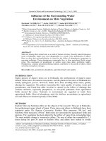
Fig. 1. Study of the morphology of the original (non-oxidized) carbon supports: (a) SEM image of CNF; (b) TEM image of CNF; (c) TEM image of CMK-3; and (d) SEM image
of Vulcan.
L. Calvillo et al. / Materials Chemistry and Physics 127 (2011) 335–341 337
Table 2
Textural parameters of the original (non-oxidized) carbon supports and their cor-
responding Pt catalysts.
Sample S
BET
(m
2
g
−1
) V
Total
(cm
3
g
−1
) S
Mesopore
(m
2
g
−1
)
S
Micropore
(m
2
g
−1
)
Vulcan 218 0.41 153 65
Pt/Vulcan 202 0.56 158 44
CNF 96 0.23 92 4
Pt/CNF 80 0.17 73 7
CMK-3 1163 0.81 1131 32
Pt/CMK-3 886 0.87 840 46
ports. TEM was also used to determine the platinum particle size and
dispersion.
X-ray diffraction (XRD) patterns were recorded using a Bruker AXS B8 Advance
diffractometer with – configuration and using Cu K␣ radiation. XRD was used to
study the morphology of both the carbon supports and metal particles.
N
2
adsorption–desorption isothermsweremeasuredat77 K using aMicromerit-
ics ASAP 2020. Total surface area and pore volume were determined using the
BET (Brunauer–Emmett–Teller) equation and the single point method, respectively.
Pore sizedistribution(PSD)curveswerecalculated by BJH (Barrett–Joyner–Halenda)
method. The positionofthemaximumofthe PSD was used astheaverageporediam-
eter. The textural properties of both the supports and catalysts were determined by
this technique.
The surface chemistry of the carbon supports (amount ofsurfaceoxygengroups)
was analyzed by temperature programmed desorption experiments. The exper-
iments were carried out from room temperature up to 1050
◦
C using a rate of
10
◦
C/min. The amounts of CO and CO
2
desorbed from the carbon samples were ana-
lyzed by gas chromatography. The determination of deconvolutions was calculated
by using Origin software.
3. Results and discussion
3.1. Characterization of carbon supports
Carbon materials proposed as catalyst supports showed mor-
phological and textural differences as well as different surface
chemistry. The effect of the differences on the catalyst properties
was investigated.
The morphology of CNF was studied by scanning and transmis-
sion electron microscopy (SEM and TEM) [22]. SEM images showed
that the carbon deposited during the decomposition of methane
appeared as long filaments that grew from the catalyst particles
(Fig. 1a), whereas TEM images showed that carbon nanofibers had
herringbone morphology (Fig. 1b). CMK-3 carbon had a highly
ordered structure that consisted of periodic arrays of hexagonal
nanorods with uniform mesopores between them, as observed by
TEM (Fig. 1c). This structure was an inverse replica of the structure
of the SBA-15 silica used as template (see Refs. [23,24]). Finally,
Vulcan XC-72R, supplied by Cabot, consisted of spherically shaped
carbon nanoparticles, called primary particles, with sizes in the
range of 30–60 nm. These particles form aggregates in the form
of chains or clusters, as shown in Fig. 1d.
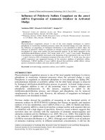
The nature of the carbon materials before the oxidation treat-
ments was studied by X-ray diffraction (XRD). CNF was the most
crystalline material, as seen in Fig. 2. They showed a sharp peak of
great intensity at 2Â = 26.24
◦
, which is assigned to the basal planes
of graphite (0 02). Vulcan XC-72R also showed one peak at around
2Â = 24.8
◦
, which was broader and less intense than the peak for
CNF. This peak is attributed to the turbostratic structure of the pri-
mary particles, which consist of “crystalline” regions of 1.5–2.0nm
in length and 1.2–1.5 nm in height with a random disposition.
However, CMK-3 carbon showed a broad peak of low intensity,
characteristic of amorphous carbon materials.
Textural properties ofthe different carbonmaterials were deter-
mined by N
2
-physisorption. Results for the non-oxidized materials
are summarized in Table 2. Vulcan XC-72R had a specific surface
area of 218m
2
g
−1
and a porevolume of 0.41cm
3
g
−1
. It hada meso-
porous structure, but contained a large number of micropores of
8070605040302010
Ni (200)
Ni (111)
Graphite (002)
CMK-3
Vulcan
Intensity (a.u.)
2-Theta (degree)
CNF
Fig. 2. XRD diffractograms of the original (non-oxidized) carbon materials used as
supports: nature of the support.
less than 1 nm (30% of the total surface area). Therefore, it is possi-
ble that an important portion of nanoparticles may be sunken into
these micropores, resulting in little or no electrochemical activity
because of thedifficulty of reactantaccessibility [7,10]. Onthe other
hand, micropores could effectively block the sinking of the metal
nanoparticles. CNF had a relatively large accessible surface area of
96 m
2
g
−1
and a pore volume of 0.23cm
3
g
−1
. They had a meso-
porous structure with an average pore diameter of approximately
4 nm (micropore volume was negligible). CMK-3 had a high specific
surface area (1163m
2
g
−1
) and a large pore volume (0.81 cm
3
g
−1
).
It was mainly a mesoporous material with narrow pore size dis-
tribution around 3 nm, although it contained a small amount of
micropores (less than 3% of the total surface area) that resulted
from the carbonization of the carbon precursor itself.
The surface chemistry of carbon materials was studied using
temperature programmed desorption (TPD) experiments. These
experiments give information about the amount, nature and ther-
mal stability of the oxygen groups contained on the carbon surface
and the oxygen groups created during the oxidation treatments.
Acidic groups are decomposed into CO
2
at lower temperatures and
basic and neutral groups are decomposed into CO at higher tem-
peratures [26–28]. It is expected that these surface oxygen groups
have two functions during the catalyst preparation by the incipi-
ent wetness impregnation method. On one hand, it is expected that
they increase the wettability of the carbon support, thereby facil-
itating the access of the aqueous solution of the metal precursor
to the internal pore structure during the impregnation stage. And
on the other hand, it is expected that they act as metal anchoring
sites, preventing the mobility and, in consequence, the agglomer-
ation of platinum particles during the metal precursor reduction
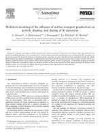
stage. Fig. 3 shows an estimation of the number of surface oxygen
groups of the original carbon materials (before the oxidation treat-
ments). CNF had a very small amount of oxygen groups due to their
inert nature, and Vulcan XC-72R only had oxygen groups desorbed
as CO. However, CMK-3 showed a high content of oxygen groups,
compared with the other materials.
The oxidation treatments affected the different properties of the
carbon materials and the effects depended on the severity of the
oxidation conditions.
338 L. Calvillo et al. / Materials Chemistry and Physics 127 (2011) 335–341
0
0,2
0,4
0,6
0,8
1
1,2
1,4
1,6
1,8
2
VulcanCMK-3CNF
mmol/g
CO
CO2
Fig. 3. Estimation of the number of surface oxygen groups of the original (non-
oxidized) carbon materials as CO and CO
2
amounts desorbed during the TPD
experiments.
Oxidation treatments affected the morphology of the carbon
materials. For CNF and Vulcan, similar results were obtained. The
less severe treatments did not modify their structure. However, it
was observed thatthe most severetreatments resulted inthe short-
ening of CNFs (see Ref. [22]) and modified the original structure of
the primary particles of Vulcan and their aggregates (see Ref. [25]).
In the case of CMK-3, the ordered structure was not altered dur-
ing the oxidation treatments (see Ref. [23]), since milder oxidation
conditions were selected for this material.
In all cases, the oxidation treatments resulted in a decrease of
both the specific surface area and the pore volume of the carbon
materials, which depended on the oxidation conditions [22,23,25].
More severe oxidation conditions resulted in a more significant
decrease of the textural properties. However, the pore size distri-
bution was not modified.
Regarding the surface chemistry, an increase in the number of
surface oxygen groups after the oxidation treatments was observed
in all cases. This result can be observed in Fig. 7, where the total
amount of oxygen groups is represented as CO +CO
2
amounts.
During these treatments, carboxylic groups, phenols and quinones
were mainly created [22,23,25]. It is expected that carboxylic
groups will increase the wettability of carbon materials, and phe-
nols and quinones, which are stable at high temperatures, will act
as anchoring sites for the metal precursor.
3.2. Physicochemical characterization of electrocatalysts
3.2.1. Effect of the nature of the support
Firstly, the effect of the use of different carbon materials as cat-
alyst support was studied. For this study, only the original carbon
materials (before the oxidation treatments) will be used. Fig. 4
shows the XRD patterns of the catalysts supported on the non-
oxidized carbon materials. All samples showed the characteristic
peaks of the fcc structure of platinum. However, the intensity and
width of the peaks, which are related to the Pt crystallite size,
depended on the carbon material used as support. The average Pt
crystallite size was determined from the XRD diffractograms using
the Scherrer’s equation and the values obtained are summarized in
Table 3
Average Pt crystallitesizeobtainedfromtheXRDdiffractogramsusingthe Scherrer’s
equation for catalysts supported on the non-oxidized carbon materials.
Catalyst Pt size (nm)
Pt/CNF 3.0
Pt/CMK-3 7.6
Pt/Vulcan 5.6
8070605040302010
Pt(220)
Pt(200)
Pt(111)
Pt/CMK-3
Pt/Vulcan
Intensity (a.u.)
2-Theta (degree)
Pt/CNF
Fig. 4. XRD diffractograms of Pt catalysts supported on the non-oxidized carbon
materials.
Table 3. The size of Pt crystallites supported on carbon nanofibers
was about 3 nm, whereas Pt crystallites supported on CMK-3 were
approximately 7.6 nm. Taking into account that all catalysts were
prepared by the same method and with the same metal loading,
it can be deduced that the support has an important effect on the
size of supported Pt crystallites. In this case, a relationship between
the Pt crystallite size and the crystalline grade of the support can
be established. The higher the crystalline grade of the support, the
smaller the Pt crystallite size. In addition, Pt crystallites supported
on Vulcan had an average size of about 5.6 nm. This value was
intermediate between those obtained for carbon nanofibers and
CMK-3, which confirms the relationship between the crystalline
grade of the support and the metal crystallite size. In the literature,
this effect is attributed to the type of metal–support interaction
[29,30], which is related to the nature of the support and has been
considered to affect the growth, the structure and the dispersion of
metal particles [4,31]. This is due to the electronic interaction at the
platinum–carbon interface, which modify the electronic structure
of the metal.
The metal–support interaction also affects the crystalline struc-
ture of the metal. Metal particles supported on CNF presented a
highly crystalline structure (Fig. 5a), which can be associated with
a strong metal–support interaction [29]. In contrast, Pt particles
supported on Vulcan and CMK-3 adopted a more dense globular
morphology (Fig. 5b and c), which can be associated to a weak
metal–support interaction.
From these results, it can be deduced that more crystalline car-
bon supports result in smaller and more crystalline Pt particles, and
that this effect is attributed to the metal–support interaction.
The size and distribution of platinum particles were also stud-
ied by transmission electron microscopy. TEM images of the
Pt catalysts showed that a uniform distribution of Pt particles
was achieved for all carbon materials by the incipient wetness
impregnation method, as observed in Fig. 6. A narrow particle
size distribution was obtained in catalysts supported on carbon
nanofibers and Vulcan. Moreover, the particle size calculated by
TEM wasin concertwith XRDresults. However,catalysts supported
on CMK-3 showed a broad particle size distribution. In this case,
although the TEM and XRD results were not in agreement, the par-
ticle size calculated by XRD corresponded to the size of the metal
aggregates observed by TEM.
L. Calvillo et al. / Materials Chemistry and Physics 127 (2011) 335–341 339
Fig. 5. TEM imagesofthePt catalystssupportedonnon-oxidized (a) CNF;(b)CMK-3;
and (c) Vulcan: crystallinity of Pt nanoparticles.
Fig. 6. TEM images of platinum catalysts supported on non-oxidized (a) CNF; (b)
CMK-3; and (c) Vulcan: dispersion of Pt nanoparticles.
340 L. Calvillo et al. / Materials Chemistry and Physics 127 (2011) 335–341
0
1
2
3
4
5
6
7
CNFCNF
NSTa0,5
CNF
NcTb0,5
CNF
NSTb0,5
CNF
NcTb2
CNF
NSTb2
Oxygen groups (mmol/g)
0
5
10
15
20
25
Pt crystallite size (nm)
Oxygen groups
Pt crystallite size
0
1
2
3
4
5
6
7
CMK-3CMK-3
NdTa0.5
CMK-3
NdTa2
CMK-3
NcTa0.5
CMK-3
NcTa2
Oxygen groups (mmol/g)
0
5
10
15
20
25
Pt cystallite size (nm)
Oxygen groups
Pt crystallite size
0
1
2
3
4
5
6
7
VulcanVulcan
NSTa0.5
Vulcan
NcTb0.5
Vulcan
NcTb2
Oxygen groups (mmol/g)
0
5
10
15
20
25
Pt crystallite size (nm)
Oxygen groups
Pt crystallite size
(a)
(b)
(c)
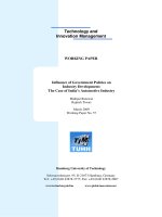
Fig. 7. Effect of the surfacechemistryofthe support on catalyst properties: relation-
ship between the total number of surface oxygen groups of the support (CO+CO
2
desorbed amounts during TPD experiments) and the average Pt crystallite size
(obtained by XRD) for oxidized and non-oxidized (a) CNF; (b) CMK-3; and (c) Vulcan.
Textural properties of catalysts were also studied by N
2
-
physisorption, and the results are summarized in Table 2. Catalysts
exhibited a lower surface area and total pore volume than the
corresponding carbon supports. In particular, the decrease of the
mesoporosity was more significant after catalyst loading when car-
bon nanofibers and CMK-3 were used as supports. This strongly
indicates that platinum was mainly distributed in the mesoporous
structure of the supports. However, a more significant decrease of
microporosity was observed in the case of Pt/Vulcan, indicating
that platinum was mainly distributed in the micropore structure.
The portion of particles inside the micropores will likely have lit-
tle or no electrochemical activity due to the difficulty of reactant
accessibility.
3.2.2. Effect of the surface chemistry of the support
The size and the aggregation grade of platinum particles are also
related to the surface chemistry of the carbon supports [32,33].
Fig. 8. TEM imagesofthePt catalysts supportedontheoxidizedmaterials. (a) Pt/CNF
NSTa0.5; (b) Pt/CMK-3 NcTa2; and (c) Pt/Vulcan NcTb2: formation of Pt agglomer-
ates.
However, it must be taken into account that the effect of the sur-
face chemistry of the support on the catalyst properties depends
on the catalyst synthesis method and the nature of the metal pre-
cursor. Therefore, it is necessary to carry out an exhaustive study
to determine the effect that the surface chemistry of the support
L. Calvillo et al. / Materials Chemistry and Physics 127 (2011) 335–341 341
has on catalyst preparation. Conclusions extracted from this study
are only valid for this catalyst synthesis method. Fig. 7 shows, for
each carbon material, the relationship between the total number of
surface oxygen groups of the support (calculated as CO + CO
2
des-
orbed amount during the TPD experiments) and the Pt crystallite
size obtained from the XRD diffractograms. The same effect of the
surface chemistry of the support was observed for all carbon mate-
rials: An increase in the platinum crystallite size was observed as
the number of surface oxygen groups increased [32].
In order to study further the effect of the oxygenated groups
of the support, catalysts supported on the oxidized supports were
analyzed by TEM (Fig. 8). The formation of Pt particles agglomer-
ates on the oxidized supports was detected. It was observed that
platinum particles deposited on oxidized carbons had a similar
size to particles deposited on the non-oxidized carbons. Hence,
the increase of crystallite size detected by XRD was due to the
formation of agglomerates, and it was not due to the formation
of larger crystallites. According to these results, for the incipient
wetness impregnation method,the agglomeration of the metalpar-
ticles asthe number of oxygen groups increases can be attributed to
the decomposition of less stable oxygen groups during the reduc-
tion stage of the metal precursor [33–35]. The decomposition of
these groups facilitates the mobility of platinum on the support
surface favouring in consequence the agglomeration of platinum
particles. This effect was more significant in catalysts supported
on oxidized CMK-3 carbons due to their higher content of oxygen
groups (Fig. 8c).
4. Conclusions
Carbon nanofibers and ordered mesoporous carbons have
been proposed as alternative supports that could replace carbon
blacks in the preparation of commercial electrocatalysts for low-
temperature fuel cells. The use of these non-conventional carbon
materials as support allowed studying the influence of support
properties on the physicochemical properties of catalysts. Thus, the
main conclusions obtained from this study are:
- The size and morphology of platinum particles depend on
the nature of the support. Higher crystalline grades of the
support are conductive to smaller platinum particle size and
higher crystalline structures, which are associated with a strong
metal–carbon interaction. However, the more amorphous the
carbon support, the higher the platinum size and the more dense
the globular morphology. These features are associated with a
weak metal–carbon interaction.
- The dispersion of metal particles also depends on the sur-
face chemistry of carbon supports. For the incipient wetness
impregnation method, the agglomeration of platinum particles
increases as the number of the surface oxygen groups of the
support increases. This is attributed to the decomposition of the
less stable surface oxygen groups during the catalyst reduction
stage, which facilitates the mobility of platinum on the sup-
port surface and, thereby favours the agglomeration of platinum
particles.
In future work, the electrochemical characterization of
these catalysts will be carried out in order to determine the
effect of the support on the electrochemical performance of
catalysts.
Acknowledgements
The authors gratefully acknowledge financial support given by
the Aragón Government under the project PM042/2007. L. Calvillo
and V. Celorrio also acknowledge the Spanish National Research
Council and CSIC for their FPI and JAE grants, respectively.
References
[1] P.P. Edwards,V.L.Kuznetsov,W.I.F. David, N.P.Brandon,EnergyPolicy 36 (2008)
4356.
[2] B.D. McNicol, D.A.J. Rand, K.R. Williams, J. Power Sources 83 (1999) 15.
[3] G.J.K. Acres, J.C. Frost, G.A. Hards, R.J. Potter, T.R. Ralph, Catal. Today 38 (1997)
393.
[4] X. Yu, S. Ye, J. Power Sources 172 (2007) 133.
[5] J H. Wee, K Y. Lee, S.H. Kim, J. Power Sources 165 (2007) 667.
[6] A. Antolini, Mater. Chem. Phys. 78 (2003) 563.
[7] H. Liu, C. Song, L. Zhang, J. Zhang, H. Wang, D.P. Wilkinson, J. Power Sources 155
(2006) 95.
[8] E. Auer, A. Freund, J. Pietsch, T. Tacke, Appl. Catal. A: Gen. 173 (1998) 259.
[9] G.S. Chai, S.B. Yoon, J S. Yu, J H. Choi, Y E. Sung, J. Phys. Chem. B 108 (2004)
7074.
[10] E. Antolini, Appl. Catal. B: Environ. 88 (2009) 1.
[11] M. Kim, J N. Park, H. Kim, S. Song, W H. Lee, J. Power Sources 163 (2006)
93.
[12] S.C. Hall, V. Subramanian, G. Teeter, B. Rambabu, Solid State Ionics 175 (2004)
809.
[13] M. Inoue, S. Akamaru, A. Taguchi, T. Abe, Vacuum 83 (2009) 658.
[14] J.R.C. Salgado, F. Alcaide, G. Álvarez, L. Calvillo, M.J. Lázaro, E. Pastor, J. Power
Sources 195 (2010) 4022.
[15] Y. Shao, G. Yin, J. Zhang, Y. Gao, Electrochim. Acta 51 (2006) 5853.
[16] K. Wikander, H. Ekström, A.E.C. Palmqvist, A. Lundblad, K. Holmberg, G. Lind-
bergh, Fuel Cells 6 (2006) 21.
[17] D. Sebastián, J.C. Calderón, J.A. González-Expósito, E. Pastor, M.V. Martínez-
Huerta, I. Suelves, R. Moliner, M.J. Lázaro, Int. J. Hydrogen Energy 35 (2010)
9934.
[18] J.B. Joo, P. Kim, W. Kim, J. Yi, J. Electroceram. 17 (2006) 713.
[19] Ch Ch Chien, K T. Jeng, Mater. Chem. Phys. 99 (2006) 80.
[20] J.R.C. Salgado,J.J.Quintana,L.Calvillo, M.J. Lázaro,P.L.Cabot,I. Esparbé,E. Pastor,
Phys. Chem. Chem. Phys. 10 (2008) 6796.
[21] J. Marie, S. Berthon-Fabry, P. Achard, M. Chatenet, A. Pradourat, E. Chainet, J.
Non-Cryst. Solids 350 (2004) 88.
[22] L. Calvillo, M.J. Lázaro, I. Suelves, Y. Echegoyen, E.G. Bordejé, R. Moliner, J.
Nanosci. Nanotechnol. 9 (2009) 4164.
[23] M.J. Lázaro, L. Calvillo, E.G. Bordejé, R. Moliner, R. Juan, C.R. Ruiz, Microporous
Mesoporous Mater. 103 (2007) 158.
[24] L. Calvillo, V. Celorrio, R. Moliner, P.L. Cabot, I. Esparbé, M.J. Lázaro, Microporous
Mesoporous Mater. 116 (2008) 292.
[25] M.J. Lázaro, L. Calvillo, V. Celorrio, J.I. Pardo, S. Perathoner, R. Moliner, in: J.
Sanders Ian, L. Peeten Thomas (Eds.), Carbon Black: Production, Properties and
Uses, Nova Science Publishers, 2011, p. 2.
[26] J.L. Figueiredo, M.F.R. Pereira, M.M.A. Freitas, J.J.M. Orfao, Carbon 37 (1999)
1379.
[27] A.E. Aksoylu, M. Madalena, A. Freitas, M.F.R. Pereira, J.L. Figueiredo, Carbon 39
(2001) 175.
[28] P.V. Samant, F. Gonc¸ alves, M.M.A. Freitas, M.F.R. Pereira, J.L. Figueiredo, Carbon
42 (2004) 1321.
[29] C.A. Bessel, K. Laubernds, N.M. Rodríguez, R.T.K. Baker, J. Phys. Chem. B 105
(2001) 1115.
[30] P. Serp, M. Corrias, P. Kalck, Appl. Catal. A: Gen. 253 (2003) 337.
[31] C. Prado-Burguete, A.Linares-Solano,F.Rodríguez-Reinoso, C. Salinas-Martínez
de Lecea, J. Catal. 115 (1989) 98.
[32] L. Calvillo, M. Gangeri, S. Perathoner, G. Centi, R. Moliner, M.J. Lázaro, J. Power
Sources 192 (2009) 144.
[33] A. Sepúlveda-Escribano, F. Coloma, F. Rodríguez-Reinoso, Appl. Catal. A: Gen.
173 (1998) 247.
[34] M.C. Román-Martínez, D. Cazorla-Amorós, A. Linares-Solano, C. Salinas-
Martínez de Lecea, Carbon 33 (1995) 3.
[35] S. Litster, G. McLean, J. Power Sources 130 (2004) 61.