s7 200 system manual en US
Bạn đang xem bản rút gọn của tài liệu. Xem và tải ngay bản đầy đủ của tài liệu tại đây (7.89 MB, 554 trang )
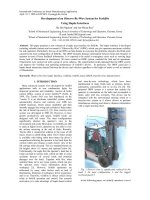
TU DONG HOA ISS WWW.ISSAUTOMATION.VN TEL: 0436369333 HOTLINE 0988999368
Preface, Contents
Product Overview
Getting Started
Installing the S7-200
3
PLC Concepts
4
Programming Concepts,
Conventions and Features
5
S7-200 Instruction Set
6
7
Hardware Troubleshooting Guide
and Software Debugging Tools
Open Loop Motion Control with
the S7-200
Creating a Program for the
Modem Module
Using the USS Protocol Library to
Control a MicroMaster Drive
Using the Modbus Protocol
Library
8
9
10
Using Recipes
13
Using Data Logs
14
PID Auto-Tune and the PID
Tuning Control Panel
S7-200
Programmable Controller
System Manual
2
Communicating over a Network
SIMATIC
1
15
Appendices
Index
This manual has the order number:
6ES7298-8FA24- 8BH0
-
Edition 08/2008
A5E00307987- 04
-
DANG KY THANH VIEN CUA WWW.ISSAUTOMATION.VN DE THUONG XUYEN NHAN DUOC TAI LIEU
11
12
TU DONG HOA ISS WWW.ISSAUTOMATION.VN TEL: 0436369333 HOTLINE 0988999368
Safety Guidelines
This manual contains notices which you should observe to ensure your own personal safety, as
well as to protect the product and connected equipment. These notices are highlighted in the
manual by a warning triangle and are marked as follows according to the level of danger:
Danger
Danger indicates an imminently hazardous situation which, if not avoided, will result in death or
serious injury.
Warning
Warning indicates a potentially hazardous situation which, if not avoided, could result in death or
serious injury.
Caution
Caution used with the safety alert symbol indicates a potentially hazardous situation which, if not
avoided, may result in minor or moderate injury.
Caution
Caution used without the safety alert symbol indicates a potentially hazardous situation which, if
not avoided, may result in property damage.
Notice
Notice indicates a potential situation which, if not avoided, may result in an undesirable result or
state.
Qualified Personnel
Only qualified personnel should be allowed to install and work on this equipment. Qualified
persons are defined as persons who are authorized to commission, to ground, and to tag circuits,
equipment, and systems in accordance with established safety practices and standards.
Correct Usage
Note the following:
Warning
This device and its components may only be used for the applications described in the catalog
or the technical descriptions, and only in connection with devices or components from other
manufacturers which have been approved or recommended by Siemens.
This product can only function correctly and safely if it is transported, stored, set up, and
installed correctly, and operated and maintained as recommended.
Trademarks
SIMATICR, SIMATIC HMIR and SIMATIC NETR are registered trademarks of SIEMENS AG.
Some of other designations used in these documents are also registered trademarks; the owner’s rights may be
violated if they are used by third parties for their own purposes.
Copyright Siemens AG 2008 All rights reserved
Disclaimer of Liability
The reproduction, transmission or use of this document or its contents is not
permitted without express written authority. Offenders will be liable for damages.
All rights, including rights created by patent grant or registration of a utility model
or design, are reserved.
We have checked the contents of this manual for agreement with the hardware and
software described. Since deviations cannot be precluded entirely, we cannot
guarantee full agreement. However, the data in this manual are reviewed regularly
and any necessary corrections included in subsequent editions. Suggestions for
improvement are welcomed.
Siemens AG
Bereich Automation and Drives
Geschaeftsgebiet Industrial Automation Systems
Postfach 4848, D- 90327 Nuernberg
E Siemens AG 2008
Technical data subject to change.
Siemens Aktiengesellschaft
6ES7298-8FA24-8BH0
ii
DANG KY THANH VIEN CUA WWW.ISSAUTOMATION.VN DE THUONG XUYEN NHAN DUOC TAI LIEU
TU DONG HOA ISS WWW.ISSAUTOMATION.VN TEL: 0436369333 HOTLINE 0988999368
Preface
Purpose of the manual
The S7-200 series is a line of micro-programmable logic controllers (Micro PLCs) that can control
a variety of automation applications. Compact design, low cost, and a powerful instruction set
make the S7-200 a perfect solution for controlling small applications. The wide variety of S7-200
models and the Windows-based programming tool give you the flexibility you need to solve your
automation problems.
This manual provides information about installing and programming the S7-200 Micro PLCs and
is designed for engineers, programmers, installers, and electricians who have a general
knowledge of programmable logic controllers.
Required Basic Knowledge
To understand this manual, it is necessary to have a general knowledge of automation and
programmable logic controllers.
Scope of the Manual
This manual is valid for STEP 7--Micro/WIN, version 4.0 and the S7-200 CPU product family. For
a complete list of the S7-200 products and order numbers described in this manual, see
Appendix A.
Changes compared to the previous version
This manual has been revised to include two new analog expansion modules and one additional
appendix.
-
EM 231 Analog Input RTD, 4 Inputs
-
EM 231 Analog Input Thermocouple 8 Inputs
-
Appendix H, S7-200CN Products
Certification
The SIMATIC S7-200 products have the following certification:
-
Underwriters Laboratories, Inc. UL 508 Listed (Industrial Control Equipment),
Registration number E75310
-
Canadian Standards Association: CSA C22.2 Number 142 (Process Control Equipment)
-
Factory Mutual Research: Class Number 3600, Class Number 3611, FM Class I, Division 2,
Groups A, B, C, & D Hazardous Locations, T4A and Class I, Zone 2, IIC, T4
Tip
The SIMATIC S7-200 series meets the CSA standard.
The cULus logo indicates that the S7-200 has been examined and certified by Underwriters
Laboratories (UL) to standards UL 508 and CSA 22.2 No. 142.
iii
DANG KY THANH VIEN CUA WWW.ISSAUTOMATION.VN DE THUONG XUYEN NHAN DUOC TAI LIEU
TU DONG HOA ISS WWW.ISSAUTOMATION.VN TEL: 0436369333 HOTLINE 0988999368
S7-200 Programmable Controller System Manual
CE Labeling
Refer to the General Technical Specifications in Appendix A for more information.
C-Tick
The SIMATIC S7-200 products are compliant with requirements of the AS/NZS 2064 (Australian)
standard.
Standards:
The SIMATIC S7-200 products fulfill the requirement and criteria of IEC 61131--2, Programmable
controllers -- Equipment requirements.
Refer to Appendix A for additional compliance information.
Place of this Documentation in the Information Environment
Product
Family
Documentation
S7-200
S7-200 Point-to-Point Interface Communication Manual (English/German)
6ES7 298-8GA00-8XH0
SIMATIC Text Display User Manual (included on the STEP 7-Micro/WIN
documentation CD)
none
HMI device OP 73micro, TP 177micro (WinCC Flexible) Operating
Instructions (English)
6AV6 691-1DF01-0AB0
SIMATIC HMI WinCC flexible 2005 Micro User’s Manual (English)
6AV6 691-1AA01-0AB0
SIMATIC NET CP 243- AS-Interface Master Manual (English)
-2
6GK7 243-2AX00-8BA0
SIMATIC NET CP 243- Communications processor of Industrial Ethernet
-1
Technical Manual (English)
J31069-D0428-U001-A2-7618
SIMATIC NET CP 243- IT Communications Processor of Industrial
-1
Ethernet and Information Technology Technical Manual (English)
J31069-D0429-U001-A2-7618
SIMATIC NET S7Beans / Applets for IT-CPs Programming Tips (English)
C79000-G8976-C180-02
SIMATIC NET GPRS/GSM-Modem SINAUT MD720- System manual
-3
(English)
C79000-G8976-C211
SIMATIC NET SINAUT MICRO SC System manual (English)
C79000-G8900-C210
SIWAREX MS Device Manual (English) (included with device)
none
S7-200 Programmable Controller System Manual (English)
6ES7 298-8FA24-8BH0
Order Number
iv
DANG KY THANH VIEN CUA WWW.ISSAUTOMATION.VN DE THUONG XUYEN NHAN DUOC TAI LIEU
TU DONG HOA ISS WWW.ISSAUTOMATION.VN TEL: 0436369333 HOTLINE 0988999368
Preface
Finding Your Way
If you are a first-time user of S7-200 Micro PLCs, you should read the entire S7-200
Programmable Controller System Manual. If you are an experienced user, refer to the table of
contents or index to find specific information.
The S7-200 Programmable Controller System Manual is organized according to the following
topics:
-
Chapter 1 (Product Overview) provides an overview of some of the features of the S7-200
family of Micro PLC products.
-
Chapter 2 (Getting Started) provides a tutorial for creating and downloading a sample
control program to an S7-200.
-
Chapter 3 (Installing the S7-200) provides the dimensions and basic guidelines for installing
the S7-200 CPU modules and expansion I/O modules.
-
Chapter 4 (PLC Concepts) provides information about the operation of the S7-200.
-
Chapter 5 (Programming Concepts, Conventions, and Features) provides information about
the features of STEP 7--Micro/WIN, the program editors and types of instructions
(IEC 1131-3 or SIMATIC), S7-200 data types, and guidelines for creating programs.
-
Chapter 6 (S7-200 Instruction Set) provides descriptions and examples of programming
instructions supported by the S7-200.
-
Chapter 7 (Communicating over a Network) provides information for setting up the different
network configurations supported by the S7-200.
-
Chapter 8 (Hardware Troubleshooting Guide and Software Debugging Tools) provides
information for troubleshooting problems with the S7-200 hardware and about the
STEP 7--Micro/WIN features that help you debug your program.
-
Chapter 9 (Open Loop Motion Control with the S7-200) provides information about three
methods of open loop motion control: Pulse Width Modulation, Pulse Train Output, and the
EM 253 Position Control Module.
-
Chapter 10 (Creating a Program for the Modem Module) provides information about the
instructions and wizard used to create a program for the EM 241 Modem module.
-
Chapter 11 (Using the USS Protocol Library to Control a MicroMaster Drive) provides
information about the instructions used to create a control program for a MicroMaster drive.
It also provides information about how to configure the MicroMaster 3 and MicroMaster 4
drives.
-
Chapter 12 (Using the Modbus Protocol Library) provides information about the instructions
used to create a program that uses the Modbus protocol for communications.
-
Chapter 13 (Using Recipes) provides information about organizing and loading automation
program recipes in the memory cartridge.
-
Chapter 14 (Using Data Logs) provides information about storing process measurement
data in the memory cartridge.
-
Chapter 15 (PID Auto-Tune and the PID Tuning Control Panel) provides information about
using these features to greatly enhance the utility and ease of use of the PID function
provided by the S7-200.
-
Appendix A (Technical Specifications) provides the technical information and data sheets
about the S7-200 hardware.
The other appendices provide additional reference information, such as descriptions of the error
codes, descriptions of the Special Memory (SM) area, part numbers for ordering S7-200
equipment, STL instruction execution times, and S7-200CN product information.
In addition to this manual, STEP 7--Micro/WIN provides extensive online help for getting started
with programming the S7-200. Included with the purchase of the STEP 7--Micro/WIN software is a
free documentation CD. On this CD you can find application tips, an electronic version of this
manual and other information.
v
DANG KY THANH VIEN CUA WWW.ISSAUTOMATION.VN DE THUONG XUYEN NHAN DUOC TAI LIEU
TU DONG HOA ISS WWW.ISSAUTOMATION.VN TEL: 0436369333 HOTLINE 0988999368
S7-200 Programmable Controller System Manual
Online Help
Help is only a keystroke away! Pressing F1 accesses the extensive online help for
STEP 7--Micro/WIN. The online help includes useful information about getting started with
programming the S7-200, as well as many other topics.
Electronic Manual
An electronic version of this S7-200 System Manual is available on the documentation CD. You
can install the electronic manual onto your computer so that you can easily access the information
in the manual while you are working with the STEP 7--Micro/WIN software.
Programming Tips
The documentation CD includes Programming Tips, a set of application examples with sample
programs. Reviewing or modifying these examples can help you find efficient or innovative
solutions for your own application. You can also find the most current version of Programming Tips
on the S7-200 Internet site.
Recycling and Disposal
Please contact a company certified in the disposal of electronic scrap for environmentally safe
recycling and disposal of your device.
Additional Support
Local Siemens Sales Office or Distributor
For assistance in answering any technical questions, for training on the S7-200 products, or for
ordering S7-200 products, contact your Siemens distributor or sales office. Because your sales
representatives are technically trained and have the most specific knowledge about your
operations, process and industry, as well as about the individual Siemens products that you are
using, they can provide the fastest and most efficient answers to any problems that you might
encounter.
Service & Support on the Internet
In addition to our documentation, we offer our Know-how online on the Internet at:
/>where you will find the following:
-
www.siemens.com/S7--200 for S7-200 product information
The S7-200 Internet site includes frequently asked questions (FAQs), Programming Tips
(application examples and sample programs), information about newly released products,
and product updates or downloads.
-
The newsletter, which constantly provides you with up-to-date information on your products.
-
The right documents via our Search function in Service & Support.
-
A forum, where users and experts from all over the world exchange their experiences.
-
Your local representative for Automation & Drives.
-
Information on field service, repairs, spare parts and more under “Services”.
Technical Services
The highly trained staff of the S7-200 Technical Services center is also available to help you solve
any problems that you might encounter. You can call on them 24 hours a day, 7 days a week.
vi
DANG KY THANH VIEN CUA WWW.ISSAUTOMATION.VN DE THUONG XUYEN NHAN DUOC TAI LIEU
TU DONG HOA ISS WWW.ISSAUTOMATION.VN TEL: 0436369333 HOTLINE 0988999368
Preface
A&D Technical Support
Worldwide, available 24 hours a day:
Nuernberg
Johnson City
Beijing
Technical Support
Worldwide (Nuernberg)
United States (Johnson City)
Asia / Australia (Beijing)
Technical Support
Technical Support and
Authorization
Technical Support and
Authorization
24 hours a day, 365 days a year
Local time: Mon.-Fri.
8:00 AM to 5:00 PM
Local time: Mon.-Fri.
8:00 AM to 5:00 PM
Phone:
Phone:
+49 (180) 5050-222
Fax:
+49 (180) 5050-223
mailto:
GMT:
+1:00
Europe / Africa (Nuernberg)
Fax:
+1 (423) 262 2522
Phone:
+86 10 64 75 75 75
+1 (800) 333-7421 (USA only)
Fax:
+86 10 64 74 74 74
+1 (423) 262 2289
mailto:
GMT:
+8:00
mailto:
GMT:
-5:00
Authorization
Local time: Mon.-Fri.
8:00 AM to 5:00 PM
Phone:
+49 (180) 5050-222
Fax:
+49 (180) 5050-223
mailto:
GMT:
+1:00
The languages of the SIMATIC Hotlines and the authorization hotline are generally German and English.
vii
DANG KY THANH VIEN CUA WWW.ISSAUTOMATION.VN DE THUONG XUYEN NHAN DUOC TAI LIEU
TU DONG HOA ISS WWW.ISSAUTOMATION.VN TEL: 0436369333 HOTLINE 0988999368
S7-200 Programmable Controller System Manual
viii
DANG KY THANH VIEN CUA WWW.ISSAUTOMATION.VN DE THUONG XUYEN NHAN DUOC TAI LIEU
TU DONG HOA ISS WWW.ISSAUTOMATION.VN TEL: 0436369333 HOTLINE 0988999368
Contents
1
Product Overview . . . . . . . . . . . . . . . . . . . . . . . . . . . . . . . . . . . . . . . . . . . . . . . . . . . . . . .
1
What’s New? . . . . . . . . . . . . . . . . . . . . . . . . . . . . . . . . . . . . . . . . . . . . . . . . . . . . . . . . . . . . . . . . . . . .
2
S7-200 Expansion Modules . . . . . . . . . . . . . . . . . . . . . . . . . . . . . . . . . . . . . . . . . . . . . . . . . . . . . . .
4
STEP 7--Micro/WIN Programming Package . . . . . . . . . . . . . . . . . . . . . . . . . . . . . . . . . . . . . . . . . .
5
Communications Options . . . . . . . . . . . . . . . . . . . . . . . . . . . . . . . . . . . . . . . . . . . . . . . . . . . . . . . . .
5
Display Panels . . . . . . . . . . . . . . . . . . . . . . . . . . . . . . . . . . . . . . . . . . . . . . . . . . . . . . . . . . . . . . . . . .
2
2
S7-200 CPU . . . . . . . . . . . . . . . . . . . . . . . . . . . . . . . . . . . . . . . . . . . . . . . . . . . . . . . . . . . . . . . . . . . .
6
Getting Started . . . . . . . . . . . . . . . . . . . . . . . . . . . . . . . . . . . . . . . . . . . . . . . . . . . . . . . . . .
7
Connecting the S7-200 CPU . . . . . . . . . . . . . . . . . . . . . . . . . . . . . . . . . . . . . . . . . . . . . . . . . . . . . .
Creating a Sample Program . . . . . . . . . . . . . . . . . . . . . . . . . . . . . . . . . . . . . . . . . . . . . . . . . . . . . . .
10
Downloading the Sample Program . . . . . . . . . . . . . . . . . . . . . . . . . . . . . . . . . . . . . . . . . . . . . . . . .
14
Placing the S7-200 in RUN Mode . . . . . . . . . . . . . . . . . . . . . . . . . . . . . . . . . . . . . . . . . . . . . . . . . .
3
8
14
Installing the S7-200 . . . . . . . . . . . . . . . . . . . . . . . . . . . . . . . . . . . . . . . . . . . . . . . . . . . . .
Guidelines for Installing S7-200 Devices . . . . . . . . . . . . . . . . . . . . . . . . . . . . . . . . . . . . . . . . . . . .
15
16
Installing and Removing the S7-200 Modules . . . . . . . . . . . . . . . . . . . . . . . . . . . . . . . . . . . . . . . .
4
17
Guidelines for Grounding and Wiring . . . . . . . . . . . . . . . . . . . . . . . . . . . . . . . . . . . . . . . . . . . . . . .
20
PLC Concepts . . . . . . . . . . . . . . . . . . . . . . . . . . . . . . . . . . . . . . . . . . . . . . . . . . . . . . . . . . .
23
Understanding How the S7-200 Executes Your Control Logic . . . . . . . . . . . . . . . . . . . . . . . . . .
24
Accessing the Data of the S7-200 . . . . . . . . . . . . . . . . . . . . . . . . . . . . . . . . . . . . . . . . . . . . . . . . . .
27
Understanding How the S7-200 Saves and Restores Data . . . . . . . . . . . . . . . . . . . . . . . . . . . . .
36
Selecting the Operating Mode for the S7-200 CPU . . . . . . . . . . . . . . . . . . . . . . . . . . . . . . . . . . . .
41
Features of the S7-200 . . . . . . . . . . . . . . . . . . . . . . . . . . . . . . . . . . . . . . . . . . . . . . . . . . . . . . . . . . .
5
40
Using the S7-200 Explorer . . . . . . . . . . . . . . . . . . . . . . . . . . . . . . . . . . . . . . . . . . . . . . . . . . . . . . . .
41
Programming Concepts, Conventions, and Features . . . . . . . . . . . . . . . . . . . . . . .
51
Guidelines for Designing a Micro PLC System . . . . . . . . . . . . . . . . . . . . . . . . . . . . . . . . . . . . . . .
52
Basic Elements of a Program . . . . . . . . . . . . . . . . . . . . . . . . . . . . . . . . . . . . . . . . . . . . . . . . . . . . . .
53
Using STEP 7--Micro/WIN to Create Your Programs . . . . . . . . . . . . . . . . . . . . . . . . . . . . . . . . . .
55
Choosing Between the SIMATIC and IEC 1131--3 Instruction Sets . . . . . . . . . . . . . . . . . . . . . .
57
Understanding the Conventions Used by the Program Editors . . . . . . . . . . . . . . . . . . . . . . . . . .
58
Using Wizards To Help You Create Your Control Program . . . . . . . . . . . . . . . . . . . . . . . . . . . . . .
60
Handling Errors in the S7-200 . . . . . . . . . . . . . . . . . . . . . . . . . . . . . . . . . . . . . . . . . . . . . . . . . . . . .
60
Assigning Addresses and Initial Values in the Data Block Editor . . . . . . . . . . . . . . . . . . . . . . . .
62
Using the Symbol Table for Symbolic Addressing of Variables . . . . . . . . . . . . . . . . . . . . . . . . . .
62
Using Local Variables . . . . . . . . . . . . . . . . . . . . . . . . . . . . . . . . . . . . . . . . . . . . . . . . . . . . . . . . . . . .
63
Using the Status Chart to Monitor Your Program . . . . . . . . . . . . . . . . . . . . . . . . . . . . . . . . . . . . . .
63
Creating an Instruction Library . . . . . . . . . . . . . . . . . . . . . . . . . . . . . . . . . . . . . . . . . . . . . . . . . . . . .
64
Features for Debugging Your Program . . . . . . . . . . . . . . . . . . . . . . . . . . . . . . . . . . . . . . . . . . . . . .
64
ix
DANG KY THANH VIEN CUA WWW.ISSAUTOMATION.VN DE THUONG XUYEN NHAN DUOC TAI LIEU
TU DONG HOA ISS WWW.ISSAUTOMATION.VN TEL: 0436369333 HOTLINE 0988999368
S7-200 Programmable Controller System Manual
6
S7-200 Instruction Set . . . . . . . . . . . . . . . . . . . . . . . . . . . . . . . . . . . . . . . . . . . . . . . . . . .
65
Conventions Used to Describe the Instructions . . . . . . . . . . . . . . . . . . . . . . . . . . . . . . . . . . . . . . .
67
S7-200 Memory Ranges and Features . . . . . . . . . . . . . . . . . . . . . . . . . . . . . . . . . . . . . . . . . . . . . .
68
Bit Logic Instructions . . . . . . . . . . . . . . . . . . . . . . . . . . . . . . . . . . . . . . . . . . . . . . . . . . . . . . . . . . . . .
70
Contacts . . . . . . . . . . . . . . . . . . . . . . . . . . . . . . . . . . . . . . . . . . . . . . . . . . . . . . . . . . . . . . . . . . .
Coils . . . . . . . . . . . . . . . . . . . . . . . . . . . . . . . . . . . . . . . . . . . . . . . . . . . . . . . . . . . . . . . . . . . . . . .
Logic Stack Instructions . . . . . . . . . . . . . . . . . . . . . . . . . . . . . . . . . . . . . . . . . . . . . . . . . . . . . .
Set and Reset Dominant Bistable Instructions . . . . . . . . . . . . . . . . . . . . . . . . . . . . . . . . . . . .
Clock Instructions . . . . . . . . . . . . . . . . . . . . . . . . . . . . . . . . . . . . . . . . . . . . . . . . . . . . . . . . . . . . . . . .
70
73
75
77
78
Communications Instructions . . . . . . . . . . . . . . . . . . . . . . . . . . . . . . . . . . . . . . . . . . . . . . . . . . . . . .
81
Network Read and Network Write Instructions . . . . . . . . . . . . . . . . . . . . . . . . . . . . . . . . . . . .
Transmit and Receive Instructions (Freeport) . . . . . . . . . . . . . . . . . . . . . . . . . . . . . . . . . . . .
Get Port Address and Set Port Address Instructions . . . . . . . . . . . . . . . . . . . . . . . . . . . . . .
Compare Instructions . . . . . . . . . . . . . . . . . . . . . . . . . . . . . . . . . . . . . . . . . . . . . . . . . . . . . . . . . . . .
81
86
95
96
Comparing Numerical Values . . . . . . . . . . . . . . . . . . . . . . . . . . . . . . . . . . . . . . . . . . . . . . . . . .
Compare String . . . . . . . . . . . . . . . . . . . . . . . . . . . . . . . . . . . . . . . . . . . . . . . . . . . . . . . . . . . . .
Conversion Instructions . . . . . . . . . . . . . . . . . . . . . . . . . . . . . . . . . . . . . . . . . . . . . . . . . . . . . . . . . . .
96
98
99
Standard Conversion Instructions . . . . . . . . . . . . . . . . . . . . . . . . . . . . . . . . . . . . . . . . . . . . . .
ASCII Conversion Instructions . . . . . . . . . . . . . . . . . . . . . . . . . . . . . . . . . . . . . . . . . . . . . . . . .
String Conversion Instructions . . . . . . . . . . . . . . . . . . . . . . . . . . . . . . . . . . . . . . . . . . . . . . . . .
Encode and Decode Instructions . . . . . . . . . . . . . . . . . . . . . . . . . . . . . . . . . . . . . . . . . . . . . . .
Counter Instructions . . . . . . . . . . . . . . . . . . . . . . . . . . . . . . . . . . . . . . . . . . . . . . . . . . . . . . . . . . . . . .
99
103
107
112
113
SIMATIC Counter Instructions . . . . . . . . . . . . . . . . . . . . . . . . . . . . . . . . . . . . . . . . . . . . . . . . .
IEC Counter Instructions . . . . . . . . . . . . . . . . . . . . . . . . . . . . . . . . . . . . . . . . . . . . . . . . . . . . . .
High-Speed Counter Instructions . . . . . . . . . . . . . . . . . . . . . . . . . . . . . . . . . . . . . . . . . . . . . . . . . . .
113
116
118
Pulse Output Instruction . . . . . . . . . . . . . . . . . . . . . . . . . . . . . . . . . . . . . . . . . . . . . . . . . . . . . . . . . .
133
Math Instructions . . . . . . . . . . . . . . . . . . . . . . . . . . . . . . . . . . . . . . . . . . . . . . . . . . . . . . . . . . . . . . . .
140
Add, Subtract, Multiply, and Divide Instructions . . . . . . . . . . . . . . . . . . . . . . . . . . . . . . . . . . .
Multiply Integer to Double Integer and Divide Integer with Remainder . . . . . . . . . . . . . . . .
Numeric Functions Instructions . . . . . . . . . . . . . . . . . . . . . . . . . . . . . . . . . . . . . . . . . . . . . . . .
Increment and Decrement Instructions . . . . . . . . . . . . . . . . . . . . . . . . . . . . . . . . . . . . . . . . . .
Proportional/Integral/Derivative (PID) Loop Instruction . . . . . . . . . . . . . . . . . . . . . . . . . . . . . . . . .
140
142
143
144
145
Interrupt Instructions . . . . . . . . . . . . . . . . . . . . . . . . . . . . . . . . . . . . . . . . . . . . . . . . . . . . . . . . . . . . .
153
Logical Operations Instructions . . . . . . . . . . . . . . . . . . . . . . . . . . . . . . . . . . . . . . . . . . . . . . . . . . . .
161
Invert Instructions . . . . . . . . . . . . . . . . . . . . . . . . . . . . . . . . . . . . . . . . . . . . . . . . . . . . . . . . . . . .
AND, OR, and Exclusive OR Instructions . . . . . . . . . . . . . . . . . . . . . . . . . . . . . . . . . . . . . . . .
Move Instructions . . . . . . . . . . . . . . . . . . . . . . . . . . . . . . . . . . . . . . . . . . . . . . . . . . . . . . . . . . . . . . . .
161
162
164
Move Byte, Word, Double Word, or Real . . . . . . . . . . . . . . . . . . . . . . . . . . . . . . . . . . . . . . . .
Move Byte Immediate (Read and Write) . . . . . . . . . . . . . . . . . . . . . . . . . . . . . . . . . . . . . . . . .
Block Move Instructions . . . . . . . . . . . . . . . . . . . . . . . . . . . . . . . . . . . . . . . . . . . . . . . . . . . . . .
Program Control Instructions . . . . . . . . . . . . . . . . . . . . . . . . . . . . . . . . . . . . . . . . . . . . . . . . . . . . . .
164
165
166
167
Conditional End . . . . . . . . . . . . . . . . . . . . . . . . . . . . . . . . . . . . . . . . . . . . . . . . . . . . . . . . . . . . .
Stop . . . . . . . . . . . . . . . . . . . . . . . . . . . . . . . . . . . . . . . . . . . . . . . . . . . . . . . . . . . . . . . . . . . . . . .
Watchdog Reset . . . . . . . . . . . . . . . . . . . . . . . . . . . . . . . . . . . . . . . . . . . . . . . . . . . . . . . . . . . . .
For--Next Loop Instructions . . . . . . . . . . . . . . . . . . . . . . . . . . . . . . . . . . . . . . . . . . . . . . . . . . . .
Jump Instructions . . . . . . . . . . . . . . . . . . . . . . . . . . . . . . . . . . . . . . . . . . . . . . . . . . . . . . . . . . . .
Sequence Control Relay (SCR) Instructions . . . . . . . . . . . . . . . . . . . . . . . . . . . . . . . . . . . . .
Diagnostic LED Instruction . . . . . . . . . . . . . . . . . . . . . . . . . . . . . . . . . . . . . . . . . . . . . . . . . . . .
167
167
167
169
171
172
178
x
DANG KY THANH VIEN CUA WWW.ISSAUTOMATION.VN DE THUONG XUYEN NHAN DUOC TAI LIEU
TU DONG HOA ISS WWW.ISSAUTOMATION.VN TEL: 0436369333 HOTLINE 0988999368
Contents
Shift and Rotate Instructions . . . . . . . . . . . . . . . . . . . . . . . . . . . . . . . . . . . . . . . . . . . . . . . . . . . . . . .
179
179
181
183
184
Table Instructions . . . . . . . . . . . . . . . . . . . . . . . . . . . . . . . . . . . . . . . . . . . . . . . . . . . . . . . . . . . . . . . .
189
Add To Table . . . . . . . . . . . . . . . . . . . . . . . . . . . . . . . . . . . . . . . . . . . . . . . . . . . . . . . . . . . . . . . .
First-In-First-Out and Last-In-First-Out . . . . . . . . . . . . . . . . . . . . . . . . . . . . . . . . . . . . . . . . . .
Memory Fill . . . . . . . . . . . . . . . . . . . . . . . . . . . . . . . . . . . . . . . . . . . . . . . . . . . . . . . . . . . . . . . . .
Table Find . . . . . . . . . . . . . . . . . . . . . . . . . . . . . . . . . . . . . . . . . . . . . . . . . . . . . . . . . . . . . . . . . .
Timer Instructions . . . . . . . . . . . . . . . . . . . . . . . . . . . . . . . . . . . . . . . . . . . . . . . . . . . . . . . . . . . . . . . .
189
190
192
193
196
SIMATIC Timer Instructions . . . . . . . . . . . . . . . . . . . . . . . . . . . . . . . . . . . . . . . . . . . . . . . . . . .
IEC Timer Instructions . . . . . . . . . . . . . . . . . . . . . . . . . . . . . . . . . . . . . . . . . . . . . . . . . . . . . . . .
Interval Timers . . . . . . . . . . . . . . . . . . . . . . . . . . . . . . . . . . . . . . . . . . . . . . . . . . . . . . . . . . . . . .
Subroutine Instructions . . . . . . . . . . . . . . . . . . . . . . . . . . . . . . . . . . . . . . . . . . . . . . . . . . . . . . . . . . .
7
179
Shift Right and Shift Left Instructions . . . . . . . . . . . . . . . . . . . . . . . . . . . . . . . . . . . . . . . . . . . .
Rotate Right and Rotate Left Instructions . . . . . . . . . . . . . . . . . . . . . . . . . . . . . . . . . . . . . . . .
Shift Register Bit Instruction . . . . . . . . . . . . . . . . . . . . . . . . . . . . . . . . . . . . . . . . . . . . . . . . . . .
Swap Bytes Instruction . . . . . . . . . . . . . . . . . . . . . . . . . . . . . . . . . . . . . . . . . . . . . . . . . . . . . . .
String Instructions . . . . . . . . . . . . . . . . . . . . . . . . . . . . . . . . . . . . . . . . . . . . . . . . . . . . . . . . . . . . . . .
196
201
203
204
Communicating over a Network . . . . . . . . . . . . . . . . . . . . . . . . . . . . . . . . . . . . . . . . . .
209
Understanding the Basics of S7-200 Network Communications . . . . . . . . . . . . . . . . . . . . . . . . .
214
Installing and Removing Communications Interfaces . . . . . . . . . . . . . . . . . . . . . . . . . . . . . . . . . .
220
Building Your Network . . . . . . . . . . . . . . . . . . . . . . . . . . . . . . . . . . . . . . . . . . . . . . . . . . . . . . . . . . . .
221
Creating User-Defined Protocols with Freeport Mode . . . . . . . . . . . . . . . . . . . . . . . . . . . . . . . . .
226
Using Modems and STEP 7--Micro/WIN with Your Network . . . . . . . . . . . . . . . . . . . . . . . . . . . .
228
Advanced Topics . . . . . . . . . . . . . . . . . . . . . . . . . . . . . . . . . . . . . . . . . . . . . . . . . . . . . . . . . . . . . . . .
233
Configuring the RS-232/PPI Multi-Master Cable for Remote Operation . . . . . . . . . . . . . . . . . . .
8
210
Selecting the Communications Protocol for Your Network . . . . . . . . . . . . . . . . . . . . . . . . . . . . . .
239
Hardware Troubleshooting Guide and Software Debugging Tools . . . . . . . . . . .
Features for Debugging Your Program . . . . . . . . . . . . . . . . . . . . . . . . . . . . . . . . . . . . . . . . . . . . . .
243
244
Displaying the Program Status . . . . . . . . . . . . . . . . . . . . . . . . . . . . . . . . . . . . . . . . . . . . . . . . . . . . .
246
Using a Status Chart to Monitor and Modify the Data in the S7-200 . . . . . . . . . . . . . . . . . . . . . .
247
Forcing Specific Values . . . . . . . . . . . . . . . . . . . . . . . . . . . . . . . . . . . . . . . . . . . . . . . . . . . . . . . . . . .
248
Hardware Troubleshooting Guide . . . . . . . . . . . . . . . . . . . . . . . . . . . . . . . . . . . . . . . . . . . . . . . . . .
9
248
Running Your Program for a Specified Number of Scans . . . . . . . . . . . . . . . . . . . . . . . . . . . . . .
249
Open Loop Motion Control with the S7-200 . . . . . . . . . . . . . . . . . . . . . . . . . . . . . . . .
251
Overview . . . . . . . . . . . . . . . . . . . . . . . . . . . . . . . . . . . . . . . . . . . . . . . . . . . . . . . . . . . . . . . . . . . . . . .
252
Using the PWM (Pulse Width Modulation) Output . . . . . . . . . . . . . . . . . . . . . . . . . . . . . . . . . . . . .
253
Basic Information for Open Loop Position Control Using Steppers or Servos . . . . . . . . . . . . . .
255
Instructions Created by the Position Control Wizard . . . . . . . . . . . . . . . . . . . . . . . . . . . . . . . . . . .
260
Error Codes for the PTO Instructions . . . . . . . . . . . . . . . . . . . . . . . . . . . . . . . . . . . . . . . . . . . . . . .
264
Features of the Position Module . . . . . . . . . . . . . . . . . . . . . . . . . . . . . . . . . . . . . . . . . . . . . . . . . . .
265
Configuring the Position Module . . . . . . . . . . . . . . . . . . . . . . . . . . . . . . . . . . . . . . . . . . . . . . . . . . .
267
Instructions Created by the Position Control Wizard for the Position Module . . . . . . . . . . . . . .
273
Sample Programs for the Position Module . . . . . . . . . . . . . . . . . . . . . . . . . . . . . . . . . . . . . . . . . . .
285
Monitoring the Position Module with the EM 253 Control Panel . . . . . . . . . . . . . . . . . . . . . . . . .
290
Error Codes for the Position Module and the Position Instructions . . . . . . . . . . . . . . . . . . . . . . .
292
Advanced Topics . . . . . . . . . . . . . . . . . . . . . . . . . . . . . . . . . . . . . . . . . . . . . . . . . . . . . . . . . . . . . . . .
294
Understanding the RP Seek Modes Supported by the Position Module . . . . . . . . . . . . . . . . . .
303
xi
DANG KY THANH VIEN CUA WWW.ISSAUTOMATION.VN DE THUONG XUYEN NHAN DUOC TAI LIEU
TU DONG HOA ISS WWW.ISSAUTOMATION.VN TEL: 0436369333 HOTLINE 0988999368
S7-200 Programmable Controller System Manual
10
Creating a Program for the Modem Module . . . . . . . . . . . . . . . . . . . . . . . . . . . . . . . .
307
Features of the Modem Module . . . . . . . . . . . . . . . . . . . . . . . . . . . . . . . . . . . . . . . . . . . . . . . . . . . .
308
Using the Modem Expansion Wizard to Configure the Modem Module . . . . . . . . . . . . . . . . . . .
314
Overview of Modem Instructions and Restrictions . . . . . . . . . . . . . . . . . . . . . . . . . . . . . . . . . . . .
318
Instructions for the Modem Module . . . . . . . . . . . . . . . . . . . . . . . . . . . . . . . . . . . . . . . . . . . . . . . . .
319
Sample Program for the Modem Module . . . . . . . . . . . . . . . . . . . . . . . . . . . . . . . . . . . . . . . . . . . .
323
S7-200 CPUs that Support Intelligent Modules . . . . . . . . . . . . . . . . . . . . . . . . . . . . . . . . . . . . . . .
323
Special Memory Location for the Modem Module . . . . . . . . . . . . . . . . . . . . . . . . . . . . . . . . . . . . .
323
Advanced Topics . . . . . . . . . . . . . . . . . . . . . . . . . . . . . . . . . . . . . . . . . . . . . . . . . . . . . . . . . . . . . . . .
325
Messaging Telephone Number Format . . . . . . . . . . . . . . . . . . . . . . . . . . . . . . . . . . . . . . . . . . . . . .
327
Text Message Format . . . . . . . . . . . . . . . . . . . . . . . . . . . . . . . . . . . . . . . . . . . . . . . . . . . . . . . . . . . .
11
328
CPU Data Transfer Message Format . . . . . . . . . . . . . . . . . . . . . . . . . . . . . . . . . . . . . . . . . . . . . . .
329
Using the USS Protocol Library to Control a MicroMaster Drive . . . . . . . . . . . . .
331
Requirements for Using the USS Protocol . . . . . . . . . . . . . . . . . . . . . . . . . . . . . . . . . . . . . . . . . . .
332
Calculating the Time Required for Communicating with the Drive . . . . . . . . . . . . . . . . . . . . . . .
332
Using the USS Instructions . . . . . . . . . . . . . . . . . . . . . . . . . . . . . . . . . . . . . . . . . . . . . . . . . . . . . . . .
333
Instructions for the USS Protocol . . . . . . . . . . . . . . . . . . . . . . . . . . . . . . . . . . . . . . . . . . . . . . . . . . .
334
Sample Programs for the USS Protocol . . . . . . . . . . . . . . . . . . . . . . . . . . . . . . . . . . . . . . . . . . . . .
341
USS Execution Error Codes . . . . . . . . . . . . . . . . . . . . . . . . . . . . . . . . . . . . . . . . . . . . . . . . . . . . . . .
342
Connecting and Setting Up the MicroMaster Series 4 Drive . . . . . . . . . . . . . . . . . . . . . . . . . . . .
12
342
Connecting and Setting Up the MicroMaster Series 3 Drive . . . . . . . . . . . . . . . . . . . . . . . . . . . .
345
Using the Modbus Protocol Library . . . . . . . . . . . . . . . . . . . . . . . . . . . . . . . . . . . . . . .
347
Overview . . . . . . . . . . . . . . . . . . . . . . . . . . . . . . . . . . . . . . . . . . . . . . . . . . . . . . . . . . . . . . . . . . . . . . .
348
Requirements for Using Modbus Protocol . . . . . . . . . . . . . . . . . . . . . . . . . . . . . . . . . . . . . . . . . . .
348
Initialization and Execution Time for Modbus Protocol . . . . . . . . . . . . . . . . . . . . . . . . . . . . . . . . .
349
Modbus Addressing . . . . . . . . . . . . . . . . . . . . . . . . . . . . . . . . . . . . . . . . . . . . . . . . . . . . . . . . . . . . . .
350
Using the Modbus Master Instructions . . . . . . . . . . . . . . . . . . . . . . . . . . . . . . . . . . . . . . . . . . . . . .
352
Instructions for the Modbus Protocol . . . . . . . . . . . . . . . . . . . . . . . . . . . . . . . . . . . . . . . . . . . . . . . .
353
Advanced Topics . . . . . . . . . . . . . . . . . . . . . . . . . . . . . . . . . . . . . . . . . . . . . . . . . . . . . . . . . . . . . . . .
13
351
Using the Modbus Slave Instructions . . . . . . . . . . . . . . . . . . . . . . . . . . . . . . . . . . . . . . . . . . . . . . .
362
Using Recipes . . . . . . . . . . . . . . . . . . . . . . . . . . . . . . . . . . . . . . . . . . . . . . . . . . . . . . . . . . .
Overview . . . . . . . . . . . . . . . . . . . . . . . . . . . . . . . . . . . . . . . . . . . . . . . . . . . . . . . . . . . . . . . . . . . . . . .
365
366
Recipe Definition and Terminology . . . . . . . . . . . . . . . . . . . . . . . . . . . . . . . . . . . . . . . . . . . . . . . . .
367
Instructions Created by the Recipe Wizard . . . . . . . . . . . . . . . . . . . . . . . . . . . . . . . . . . . . . . . . . .
14
367
Using the Recipe Wizard . . . . . . . . . . . . . . . . . . . . . . . . . . . . . . . . . . . . . . . . . . . . . . . . . . . . . . . . . .
371
Using Data Logs . . . . . . . . . . . . . . . . . . . . . . . . . . . . . . . . . . . . . . . . . . . . . . . . . . . . . . . .
373
Overview . . . . . . . . . . . . . . . . . . . . . . . . . . . . . . . . . . . . . . . . . . . . . . . . . . . . . . . . . . . . . . . . . . . . . . .
375
Instruction Created by the Data Log Wizard . . . . . . . . . . . . . . . . . . . . . . . . . . . . . . . . . . . . . . . . . .
15
374
Using the Data Log Wizard . . . . . . . . . . . . . . . . . . . . . . . . . . . . . . . . . . . . . . . . . . . . . . . . . . . . . . . .
379
PID Auto-Tune and the PID Tuning Control Panel . . . . . . . . . . . . . . . . . . . . . . . . . .
381
Understanding the PID Auto-Tune . . . . . . . . . . . . . . . . . . . . . . . . . . . . . . . . . . . . . . . . . . . . . . . . . .
382
Expanded Loop Table . . . . . . . . . . . . . . . . . . . . . . . . . . . . . . . . . . . . . . . . . . . . . . . . . . . . . . . . . . . .
382
Prerequisites . . . . . . . . . . . . . . . . . . . . . . . . . . . . . . . . . . . . . . . . . . . . . . . . . . . . . . . . . . . . . . . . . . . .
385
Auto-Hysteresis and Auto-Deviation . . . . . . . . . . . . . . . . . . . . . . . . . . . . . . . . . . . . . . . . . . . . . . . .
385
Auto-Tune Sequence . . . . . . . . . . . . . . . . . . . . . . . . . . . . . . . . . . . . . . . . . . . . . . . . . . . . . . . . . . . . .
386
xii
DANG KY THANH VIEN CUA WWW.ISSAUTOMATION.VN DE THUONG XUYEN NHAN DUOC TAI LIEU
TU DONG HOA ISS WWW.ISSAUTOMATION.VN TEL: 0436369333 HOTLINE 0988999368
Contents
Exception Conditions . . . . . . . . . . . . . . . . . . . . . . . . . . . . . . . . . . . . . . . . . . . . . . . . . . . . . . . . . . . . .
387
PID Tuning Control Panel . . . . . . . . . . . . . . . . . . . . . . . . . . . . . . . . . . . . . . . . . . . . . . . . . . . . . . . . .
A
387
Notes Concerning PV Out-of-Range (Result Code 3) . . . . . . . . . . . . . . . . . . . . . . . . . . . . . . . . . .
388
Technical Specifications . . . . . . . . . . . . . . . . . . . . . . . . . . . . . . . . . . . . . . . . . . . . . . . . .
General Technical Specifications . . . . . . . . . . . . . . . . . . . . . . . . . . . . . . . . . . . . . . . . . . . . . . . . . . .
391
392
CPU Specifications . . . . . . . . . . . . . . . . . . . . . . . . . . . . . . . . . . . . . . . . . . . . . . . . . . . . . . . . . . . . . .
396
Digital Expansion Modules Specifications . . . . . . . . . . . . . . . . . . . . . . . . . . . . . . . . . . . . . . . . . . .
405
Analog Expansion Modules Specifications . . . . . . . . . . . . . . . . . . . . . . . . . . . . . . . . . . . . . . . . . . .
412
Thermocouple and RTD Expansion Modules Specifications . . . . . . . . . . . . . . . . . . . . . . . . . . . .
424
EM 277 PROFIBUS--DP Module Specifications . . . . . . . . . . . . . . . . . . . . . . . . . . . . . . . . . . . . . .
438
EM 241 Modem Module Specifications . . . . . . . . . . . . . . . . . . . . . . . . . . . . . . . . . . . . . . . . . . . . . .
450
EM 253 Position Module Specifications . . . . . . . . . . . . . . . . . . . . . . . . . . . . . . . . . . . . . . . . . . . . .
452
(CP 243--1) Ethernet Module Specifications . . . . . . . . . . . . . . . . . . . . . . . . . . . . . . . . . . . . . . . . .
458
(CP 243--1 IT) Internet Module Specifications . . . . . . . . . . . . . . . . . . . . . . . . . . . . . . . . . . . . . . . .
460
(CP 243--2) AS--Interface Module Specifications . . . . . . . . . . . . . . . . . . . . . . . . . . . . . . . . . . . . . .
463
Optional Cartridges . . . . . . . . . . . . . . . . . . . . . . . . . . . . . . . . . . . . . . . . . . . . . . . . . . . . . . . . . . . . . .
465
I/O Expansion Cable . . . . . . . . . . . . . . . . . . . . . . . . . . . . . . . . . . . . . . . . . . . . . . . . . . . . . . . . . . . . .
466
RS-232/PPI Multi-Master Cable and USB/PPI Multi-Master Cable . . . . . . . . . . . . . . . . . . . . . .
467
Input Simulators . . . . . . . . . . . . . . . . . . . . . . . . . . . . . . . . . . . . . . . . . . . . . . . . . . . . . . . . . . . . . . . . .
471
B
Calculating a Power Budget . . . . . . . . . . . . . . . . . . . . . . . . . . . . . . . . . . . . . . . . . . . . . .
473
C
Error Codes . . . . . . . . . . . . . . . . . . . . . . . . . . . . . . . . . . . . . . . . . . . . . . . . . . . . . . . . . . . . .
477
Fatal Error Codes and Messages . . . . . . . . . . . . . . . . . . . . . . . . . . . . . . . . . . . . . . . . . . . . . . . . . .
479
Compile Rule Violations . . . . . . . . . . . . . . . . . . . . . . . . . . . . . . . . . . . . . . . . . . . . . . . . . . . . . . . . . .
D
478
Run-Time Programming Problems . . . . . . . . . . . . . . . . . . . . . . . . . . . . . . . . . . . . . . . . . . . . . . . . .
480
Special Memory (SM) Bits . . . . . . . . . . . . . . . . . . . . . . . . . . . . . . . . . . . . . . . . . . . . . . . .
481
SMB0: Status Bits . . . . . . . . . . . . . . . . . . . . . . . . . . . . . . . . . . . . . . . . . . . . . . . . . . . . . . . . . . . . . . .
482
SMB1: Status Bits . . . . . . . . . . . . . . . . . . . . . . . . . . . . . . . . . . . . . . . . . . . . . . . . . . . . . . . . . . . . . . .
482
SMB2: Freeport Receive Character . . . . . . . . . . . . . . . . . . . . . . . . . . . . . . . . . . . . . . . . . . . . . . . .
483
SMB3: Freeport Parity Error . . . . . . . . . . . . . . . . . . . . . . . . . . . . . . . . . . . . . . . . . . . . . . . . . . . . . . .
483
SMB4: Queue Overflow . . . . . . . . . . . . . . . . . . . . . . . . . . . . . . . . . . . . . . . . . . . . . . . . . . . . . . . . . . .
483
SMB5: I/O Status . . . . . . . . . . . . . . . . . . . . . . . . . . . . . . . . . . . . . . . . . . . . . . . . . . . . . . . . . . . . . . . .
484
SMB6: CPU ID Register . . . . . . . . . . . . . . . . . . . . . . . . . . . . . . . . . . . . . . . . . . . . . . . . . . . . . . . . . .
484
SMB7: Reserved . . . . . . . . . . . . . . . . . . . . . . . . . . . . . . . . . . . . . . . . . . . . . . . . . . . . . . . . . . . . . . . .
484
SMB8 to SMB21: I/O Module ID and Error Registers . . . . . . . . . . . . . . . . . . . . . . . . . . . . . . . . . .
485
SMW22 to SMW26: Scan Times . . . . . . . . . . . . . . . . . . . . . . . . . . . . . . . . . . . . . . . . . . . . . . . . . . .
486
SMB28 and SMB29: Analog Adjustment . . . . . . . . . . . . . . . . . . . . . . . . . . . . . . . . . . . . . . . . . . . .
486
SMB30 and SMB130: Freeport Control Registers . . . . . . . . . . . . . . . . . . . . . . . . . . . . . . . . . . . . .
486
SMB31 and SMW32: Permanent Memory (EEPROM) Write Control . . . . . . . . . . . . . . . . . . . . .
487
SMB34 and SMB35: Time Interval Registers for Timed Interrupts . . . . . . . . . . . . . . . . . . . . . . .
487
SMB36 to SMB65: HSC0, HSC1, and HSC2 Register . . . . . . . . . . . . . . . . . . . . . . . . . . . . . . . . .
487
SMB66 to SMB85: PTO/PWM Registers . . . . . . . . . . . . . . . . . . . . . . . . . . . . . . . . . . . . . . . . . . . .
489
SMB86 to SMB94, and SMB186 to SMB194: Receive Message Control . . . . . . . . . . . . . . . . .
490
SMW98: Errors on the Expansion I/O Bus . . . . . . . . . . . . . . . . . . . . . . . . . . . . . . . . . . . . . . . . . . .
491
SMB130: Freeport Control Register (see SMB30) . . . . . . . . . . . . . . . . . . . . . . . . . . . . . . . . . . . .
491
SMB131 to SMB165: HSC3, HSC4, and HSC5 Register . . . . . . . . . . . . . . . . . . . . . . . . . . . . . . .
491
SMB166 to SMB185: PTO0, PTO1 Profile Definition Table . . . . . . . . . . . . . . . . . . . . . . . . . . . . .
492
xiii
DANG KY THANH VIEN CUA WWW.ISSAUTOMATION.VN DE THUONG XUYEN NHAN DUOC TAI LIEU
TU DONG HOA ISS WWW.ISSAUTOMATION.VN TEL: 0436369333 HOTLINE 0988999368
S7-200 Programmable Controller System Manual
SMB186 to SMB194: Receive Message Control (see SMB86 to SMB94) . . . . . . . . . . . . . . . . .
492
SMB200 to SMB549: Intelligent Module Status . . . . . . . . . . . . . . . . . . . . . . . . . . . . . . . . . . . . . . .
493
E
S7-200 Order Numbers . . . . . . . . . . . . . . . . . . . . . . . . . . . . . . . . . . . . . . . . . . . . . . . . . . .
495
F
Execution Times for STL Instructions . . . . . . . . . . . . . . . . . . . . . . . . . . . . . . . . . . . . .
499
G
S7-200 Quick Reference Information . . . . . . . . . . . . . . . . . . . . . . . . . . . . . . . . . . . . . .
505
H
S7-200CN Products . . . . . . . . . . . . . . . . . . . . . . . . . . . . . . . . . . . . . . . . . . . . . . . . . . . . . .
511
Certifications and Approvals for S7-200CN Products . . . . . . . . . . . . . . . . . . . . . . . . . . . . . . . . . .
512
S7-200CN Products . . . . . . . . . . . . . . . . . . . . . . . . . . . . . . . . . . . . . . . . . . . . . . . . . . . . . . . . . . . . . .
513
xiv
DANG KY THANH VIEN CUA WWW.ISSAUTOMATION.VN DE THUONG XUYEN NHAN DUOC TAI LIEU
TU DONG HOA ISS WWW.ISSAUTOMATION.VN TEL: 0436369333 HOTLINE 0988999368
Product Overview
The S7-200 series of micro-programmable logic controllers (Micro PLCs) can control a wide
variety of devices to support your automation needs.
The S7-200 monitors inputs and changes outputs as controlled by the user program, which can
include Boolean logic, counting, timing, complex math operations, and communications with other
intelligent devices. The compact design, flexible configuration, and powerful instruction set
combine to make the S7-200 a perfect solution for controlling a wide variety of applications.
In This Chapter
What’s New? . . . . . . . . . . . . . . . . . . . . . . . . . . . . . . . . . . . . . . . . . . . . . . . . . . . . . . . . . . . . . . . . . . . .
2
S7-200 CPU . . . . . . . . . . . . . . . . . . . . . . . . . . . . . . . . . . . . . . . . . . . . . . . . . . . . . . . . . . . . . . . . . . . .
2
S7-200 Expansion Modules . . . . . . . . . . . . . . . . . . . . . . . . . . . . . . . . . . . . . . . . . . . . . . . . . . . . . . .
4
STEP 7--Micro/WIN Programming Package . . . . . . . . . . . . . . . . . . . . . . . . . . . . . . . . . . . . . . . . . .
5
Communications Options . . . . . . . . . . . . . . . . . . . . . . . . . . . . . . . . . . . . . . . . . . . . . . . . . . . . . . . . .
5
Display Panels . . . . . . . . . . . . . . . . . . . . . . . . . . . . . . . . . . . . . . . . . . . . . . . . . . . . . . . . . . . . . . . . . .
6
1
DANG KY THANH VIEN CUA WWW.ISSAUTOMATION.VN DE THUONG XUYEN NHAN DUOC TAI LIEU
TU DONG HOA ISS WWW.ISSAUTOMATION.VN TEL: 0436369333 HOTLINE 0988999368
S7-200 Programmable Controller System Manual
What’s New?
The new features of the SIMATIC S7-200 include two new analog expansion modules:
-
EM 231 Analog Input RTD, 4 Inputs
-
EM 231 Analog Input Thermocouple 8 Inputs
-
Appendix H, S7-200CN Products
S7-200 CPU
The S7-200 CPU combines a microprocessor, an integrated power supply, input circuits, and
output circuits in a compact housing to create a powerful Micro PLC. See Figure 1-1. After you
have downloaded your program, the S7-200 contains the logic required to monitor and control the
input and output devices in your application.
Status LEDs:
System Fault/Diagnostic
(SF/DIAG)
RUN
STOP
I/O LEDs
Optional cartridge:
Memory Cartridge
Real-time Clock
Battery
Communications port
Figure 1-1
Access door:
Mode selector switch (RUN/STOP)
Analog adjustment potentiometer(s)
Expansion port (for most CPUs)
Terminal connector
(removable on CPU 224, CPU 224XP
and CPU 226)
Clip for installation on a standard (DIN) rail
S7-200 Micro PLC
2
DANG KY THANH VIEN CUA WWW.ISSAUTOMATION.VN DE THUONG XUYEN NHAN DUOC TAI LIEU
TU DONG HOA ISS WWW.ISSAUTOMATION.VN TEL: 0436369333 HOTLINE 0988999368
Product Overview
Chapter 1
Siemens provides different S7-200 CPU models with a diversity of features and capabilities that
help you create effective solutions for your varied applications. Table 1-1 briefly compares some of
the features of the CPU. For detailed information about a specific CPU, see Appendix A.
Table 1-1
Comparison of the S7-200 CPU Models
Feature
CPU 221
CPU 222
CPU 224
CPU 224XP
CPU 224XPsi
CPU 226
Physical size (mm)
90 x 80 x 62
90 x 80 x 62
120.5 x 80 x 62
140 x 80 x 62
190 x 80 x 62
Program memory:
with run mode edit
without run mode edit
4096 bytes
4096 bytes
4096 bytes
4096 bytes
8192 bytes
12288 bytes
12288 bytes
16384 bytes
16384 bytes
24576 bytes
Data memory
2048 bytes
2048 bytes
8192 bytes
10240 bytes
10240 bytes
Memory backup
50 hours
typical
50 hours
typical
100 hours
typical
100 hours
typical
100 hours
typical
Local on-board I/O
Digital
Analog
6 In/4 Out
-
8 In/6 Out
-
14 In/10 Out
-
14 In/10 Out
2 In/1 Out
24 In/16 Out
-
Expansion modules
0 modules
2 modules1
7 modules1
7 modules1
7 modules1
High-speed counters
Single phase
4 at 30 kHz
4 at 30 kHz
6 at 30 kHz
6 at 30 kHz
2 at 20 kHz
2 at 20 kHz
4 at 20 kHz
4 at 30 kHz
2 at 200 kHz
3 at 20 kHz
1 at 100 kHz
Pulse outputs (DC)
2 at 20 kHz
2 at 20 kHz
2 at 20 kHz
2 at 100 kHz
2 at 20 kHz
Analog adjustments
1
1
2
2
2
Real-time clock
Cartridge
Cartridge
Built-in
Built-in
Built-in
Communications ports
1
1
1
2
2
Floating-point math
Yes
Digital I/O image size
256 (128 in, 128 out)
Boolean execution
speed
0.22 microseconds/instruction
Two phase
1
RS-485
RS-485
RS-485
RS-485
4 at 20 kHz
RS-485
You must calculate your power budget to determine how much power (or current) the S7-200 CPU can provide for your configuration. If the CPU
power budget is exceeded, you may not be able to connect the maximum number of modules. See Appendix A for CPU and expansion module
power requirements, and Appendix B to calculate your power budget.
3
DANG KY THANH VIEN CUA WWW.ISSAUTOMATION.VN DE THUONG XUYEN NHAN DUOC TAI LIEU
TU DONG HOA ISS WWW.ISSAUTOMATION.VN TEL: 0436369333 HOTLINE 0988999368
S7-200 Programmable Controller System Manual
S7-200 Expansion Modules
To better solve your application requirements, the S7-200 family includes a wide variety of
expansion modules. You can use these expansion modules to add additional functionality to the
S7-200 CPU. Table 1-2 provides a list of the expansion modules that are currently available. For
detailed information about a specific module, see Appendix A.
Table 1-2
S7-200 Expansion Modules
Expansion
Modules
Type
Discrete modules
Input
8 x DC In
8 x AC In
16 x DC In
Output
4 x DC Out
4 x Relays
8 x Relay
8 x DC Out
8 x AC Out
4 x DC In/
4 x DC Out
8 x DC In/
8 x DC Out
16 x DC In/
16 x DC Out
32 x DC In/
32 x DC Out
4 x DC In /
4 x Relay
8 x DC In /
8 x Relay
16 x DC In/
16 x Relay
32 x DC In/
32 x Relay
4 x Analog In
8 x Analog In
4 x Thermocouple In
8 x Thermocouple In
Combination
Analog modules
Input
2 x RTD In
4 x RTD In
Output
2 x Analog Out
4 x Analog Out
Combination
4 x Analog In
4 x Analog Out
Intelligent modules
Position
Modem
Ethernet
Ethernet IT
AS-Interface
PROFIBUS-DP
SIWAREX MS1
Other modules
1
Detailed information not included in Appendix A. Please refer to your module documentation.
4
DANG KY THANH VIEN CUA WWW.ISSAUTOMATION.VN DE THUONG XUYEN NHAN DUOC TAI LIEU
TU DONG HOA ISS WWW.ISSAUTOMATION.VN TEL: 0436369333 HOTLINE 0988999368
Product Overview
Chapter 1
STEP 7-Micro/WIN Programming Package
The STEP 7--Micro/WIN programming package provides a user-friendly environment to develop,
edit, and monitor the logic needed to control your application. STEP 7--Micro/WIN provides three
program editors for convenience and efficiency in developing the control program for your
application. To help you find the information you need, STEP 7--Micro/WIN provides an extensive
online help system and a documentation CD that contains an electronic version of this manual,
application tips, and other useful information.
Computer Requirements
STEP 7--Micro/WIN runs on either a personal computer or a Siemens programming device, such
as a PG 760. Your computer or programming device should meet the following minimum
requirements:
-
Operating system:
Windows 2000, Windows XP, Vista
-
At least 350M bytes of free hard
disk space
-
Mouse (recommended)
Figure 1-2
STEP 7-Micro/WIN
Installing STEP 7-Micro/WIN
Insert the STEP 7--Micro/WIN CD into the CD-ROM drive of your computer. The installation wizard
starts automatically and prompts you through the installation process. Refer to the Readme file for
more information about installing STEP 7--Micro/WIN.
Tip
To install STEP 7--Micro/WIN on a Windows 2000, Windows XP, or Windows Vista operating
system, you must log in with Administrator privileges.
Communications Options
Siemens provides two programming options for connecting your computer to your S7-200: a direct
connection with a PPI Multi-Master cable, or a Communications Processor (CP) card with an MPI
cable.
The PPI Multi-Master programming cable is the most common and economical method of
connecting your computer to the S7-200. This cable connects the communications port of the
S7-200 to the serial communications of your computer. The PPI Multi-Master programming cable
can also be used to connect other communications devices to the S7-200.
5
DANG KY THANH VIEN CUA WWW.ISSAUTOMATION.VN DE THUONG XUYEN NHAN DUOC TAI LIEU
TU DONG HOA ISS WWW.ISSAUTOMATION.VN TEL: 0436369333 HOTLINE 0988999368
S7-200 Programmable Controller System Manual
Display Panels
Text Display Units
The Text Display (TD) is a display device that can be connected to the S7-200. Using the Text
Display wizard, you can easily program your S7-200 to display text messages and other data
pertaining to your application.
The TD device provides a low cost interface to your application by allowing you to view, monitor,
and change the process variables pertaining to your application.
The S7-200 product family provides four TD devices:
-
The TD100C has a 4-line text
display with 2 font choices.
-
The TD 200C has a 2-line text
display with 20 characters per line
for a total of 40 characters.
-
The TD400C can have a 2- or
2
4-line text display depending on
your font and character choice.
TD400C
TD 200C
The TD 200 has a faceplate which
provides four keys with predefined,
set-bit functions and allows up to
eight set-bit functions.
-
TD 200
TD 100C
Text Display
Figure 1-3
Text Display Units
For more information about the Text Display Units, refer to the SIMATIC Text Display (TD) User
Manual on the STEP 7--Micro/WIN docuCD.
The Text Display wizard in STEP 7--Micro/WIN helps you configure Text Display messages
quickly and easily. To start the Text Display wizard, select the Tools > Text Display Wizard menu
command.
Operator and Touch Panel Displays
The OP 73micro and TP 177micro
panels are tailored to applications with
SIMATIC S7-200 Micro PLC and provide
operating and monitoring functions for
small-scale machines and plants. Short
configuration and commissioning times,
and their configuration in WinCC flexible
form the highlights of these panels. In
addition, these panels support up to 32
configuration languages and five online
languages, including the Asian and
Cyrillic character sets.
The mounting dimensions of the
Operator Panel OP 73micro with its
graphical 3” display unit are compatible
with OP3 and TD 200.
Touch Panel TP 177micro replaces the
Touch Panel TP 070/TP 170micro. It can
be mounted vertically to accommodate
additional applications. This feature
enables its use even when space is
restricted.
Figure 1-4
Operator and Touch Panel Displays
6
DANG KY THANH VIEN CUA WWW.ISSAUTOMATION.VN DE THUONG XUYEN NHAN DUOC TAI LIEU
TU DONG HOA ISS WWW.ISSAUTOMATION.VN TEL: 0436369333 HOTLINE 0988999368
Getting Started
STEP 7--Micro/WIN makes it easy for you to program your S7-200. In just a few short steps using
a simple example, you can learn how to connect, program, and run your S7-200.
All you need for this example is a PPI Multi-Master cable, an S7-200 CPU, and a programming
device running the STEP 7--Micro/WIN programming software.
In This Chapter
Connecting the S7-200 CPU . . . . . . . . . . . . . . . . . . . . . . . . . . . . . . . . . . . . . . . . . . . . . . . . . . . . . .
8
Creating a Sample Program . . . . . . . . . . . . . . . . . . . . . . . . . . . . . . . . . . . . . . . . . . . . . . . . . . . . . . .
10
Downloading the Sample Program . . . . . . . . . . . . . . . . . . . . . . . . . . . . . . . . . . . . . . . . . . . . . . . . .
14
Placing the S7-200 in RUN Mode . . . . . . . . . . . . . . . . . . . . . . . . . . . . . . . . . . . . . . . . . . . . . . . . . .
14
7
DANG KY THANH VIEN CUA WWW.ISSAUTOMATION.VN DE THUONG XUYEN NHAN DUOC TAI LIEU
TU DONG HOA ISS WWW.ISSAUTOMATION.VN TEL: 0436369333 HOTLINE 0988999368
S7-200 Programmable Controller System Manual
Connecting the S7-200 CPU
Connecting your S7-200 is easy. For this example, you only need to connect power to your
S7-200 CPU and then connect the communications cable between your programming device and
the S7-200 CPU.
Connecting Power to the S7-200 CPU
The first step is to connect the S7-200 to a power source. Figure 2-1 shows the wiring
connections for either a DC or an AC model of the S7-200 CPU.
Before you install or remove any electrical device, ensure that the power to that equipment has
been turned off. Always follow appropriate safety precautions and ensure that power to the
S7-200 is disabled before attempting to install or remove the S7-200.
Warning
Attempts to install or wire the S7-200 or related equipment with power applied could cause
electric shock or faulty operation of equipment. Failure to disable all power to the S7-200 and
related equipment during installation or removal procedures could result in death or serious
injury to personnel, and/or damage to equipment.
Always follow appropriate safety precautions and ensure that power to the S7-200 is disabled
before attempting to install or remove the S7-200 or related equipment.
24 VDC
DC Installation
Figure 2-1
85 to 265 VAC
AC Installation
Connecting Power to the S7-200 CPU
8
DANG KY THANH VIEN CUA WWW.ISSAUTOMATION.VN DE THUONG XUYEN NHAN DUOC TAI LIEU
TU DONG HOA ISS WWW.ISSAUTOMATION.VN TEL: 0436369333 HOTLINE 0988999368
Getting Started
Chapter 2
Connecting the RS-232/PPI Multi-Master Cable
Figure 2-2 shows an RS-232/PPI
Multi-Master cable connecting the
S7-200 to the programming device. To
connect the cable:
1.
2.
3.
Programming
Device
S7-200
Connect the RS-232 connector
(marked “PC”) of the RS-232/PPI
Multi-Master cable to the
communications port of the
programming device. (For this
example, connect to COM 1.)
Connect the RS-485 connector
(marked “PPI”) of the RS-232/PPI
Multi-Master cable to Port 0 or
Port 1 of the S7-200.
Ensure that the DIP switches of
the RS-232/PPI Multi-Master cable
are set as shown in Figure 2-2.
RS-232/PPI
Multi-Master Cable
↑1 -- On
↓0 -- Off
1 2 3 4 5 6 7 8
Figure 2-2
Connecting the RS-232/PPI Multi-Master Cable
Tip
Examples in this manual use the RS-232/PPI Multi-Master cable. The RS-232/PPI Multi-Master
cable replaces the previous PC/PPI cable. A USB/PPI Multi-Master cable is also available.
Refer to Appendix E for order numbers.
Starting STEP 7-Micro/WIN
Click on the STEP 7--Micro/WIN icon to
open a new project. Figure 2-3 shows a
new project.
Navigation bar
Notice the navigation bar. You can use
the icons on the navigation bar to open
elements of the STEP 7--Micro/WIN
project.
Click on the Communications icon in the
navigation bar to display the
Communications dialog box. You use
this dialog box to set up the
communications for STEP 7--Micro/WIN.
Communications icon
Figure 2-3
New STEP 7-Micro/WIN Project
9
DANG KY THANH VIEN CUA WWW.ISSAUTOMATION.VN DE THUONG XUYEN NHAN DUOC TAI LIEU
TU DONG HOA ISS WWW.ISSAUTOMATION.VN TEL: 0436369333 HOTLINE 0988999368
S7-200 Programmable Controller System Manual
Verifying the Communications Parameters for STEP 7-Micro/WIN
The example project uses the default settings for STEP 7--Micro/WIN and the RS-232/PPI
Multi-Master cable. To verify these settings:
1.
Verify that the address of the
PC/PPI cable in the
Communications dialog box is set
to 0.
2.
Verify that the interface for the
network parameter is set for
PC/PPI cable(COM1).
3.
Verify that the transmission rate is
set to 9.6 kbps.
If you need to change your
communications parameter settings, see
Chapter 7.
Figure 2-4
Verifying the Communications Parameters
Establishing Communications with the S7-200
Use the Communications dialog box to connect with your S7-200 CPU:
1.
Double-click the refresh icon in the
Communications dialog box.
STEP 7--Micro/WIN searches for
the S7-200 station and displays a
CPU icon for the connected
S7-200 station.
2.
Select the S7-200 and click OK.
If STEP 7--Micro/WIN does not find your
S7-200 CPU, check the settings for the
communications parameters and repeat
these steps.
After you have established
communications with the S7-200, you
co
u cat o s t t e S 00,
are ready to create and download the
example program.
Figure 2-5
Establishing Communications to the S7-200
Creating a Sample Program
Entering this example of a control program will help you understand how easy it is to use
STEP 7--Micro/WIN. This program uses six instructions in three networks to create a very simple,
self-starting timer that resets itself.
For this example, you use the Ladder (LAD) editor to enter the instructions for the program. The
following example shows the complete program in both LAD and Statement List (STL). The
network comments in the STL program explain the logic for each network. The timing diagram
shows the operation of the program.
10
DANG KY THANH VIEN CUA WWW.ISSAUTOMATION.VN DE THUONG XUYEN NHAN DUOC TAI LIEU
TU DONG HOA ISS WWW.ISSAUTOMATION.VN TEL: 0436369333 HOTLINE 0988999368
Getting Started
Chapter 2
Example: Sample Program for getting started with STEP 7- Micro/WIN
Network 1
LDN
TON
//10 ms timer T33 times out after
//(100 x 10 ms = 1 s) M0.0 pulse is
// too fast to monitor with Status view.
M0.0
T33, +100
Network 2
LDW>=
=
//Comparison becomes true at a
//rate that is visible with
//Status view. Turn on Q0.0 after
//(40 x 10 ms = 0.4 s), for a
// 40% OFF/60% ON waveform.
T33, +40
Q0.0
Network 3
LD
=
//T33 (bit) pulse too fast to monitor with
//Status view. Reset the timer through
//M0.0 after the (100 x 10 ms = 1 s) period.
T33
M0.0
Timing Diagram
current = 100
current = 40
T33 (current)
0.4s 0.6s
T33 (bit)
M0.0
Q0.0
Opening the Program Editor
Click on the Program Block icon to open
the program editor. See Figure 2-6.
Notice the instruction tree and the
program editor. You use the instruction
tree to insert the LAD instructions into
the networks of the program editor by
dragging and dropping the instructions
from the instruction tree to the networks.
Program editor
The toolbar icons provide shortcuts to
the menu commands.
Instruction tree
After you enter and save the program,
you can download the program to the
S7-200.
Figure 2-6
STEP 7-Micro/WIN Window
11
DANG KY THANH VIEN CUA WWW.ISSAUTOMATION.VN DE THUONG XUYEN NHAN DUOC TAI LIEU