Astm a 716 08 (2014)
Bạn đang xem bản rút gọn của tài liệu. Xem và tải ngay bản đầy đủ của tài liệu tại đây (169.16 KB, 5 trang )
Designation: A716 − 08 (Reapproved 2014)
Standard Specification for
Ductile Iron Culvert Pipe1
This standard is issued under the fixed designation A716; the number immediately following the designation indicates the year of
original adoption or, in the case of revision, the year of last revision. A number in parentheses indicates the year of last reapproval. A
superscript epsilon (´) indicates an editorial change since the last revision or reapproval.
1. Scope
3. General Requirements
1.1 This specification covers 14 to 64-in. ductile-iron culvert pipe centrifugally cast.
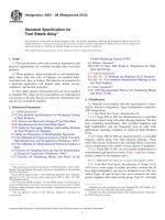
3.1 The pipe shall be manufactured of ductile iron that
meets the requirements of Sections 6 and 7. See Table 1 for
pipe thicknesses and weights; see also Fig. 1.
1.2 The values stated in inch-pound units are to be regarded
as standard. The values given in parentheses are mathematical
conversions to SI units that are provided for information only
and are not considered standard.
3.2 The pipe shall be provided with suitable joints, such as
push-on or other types of joints that prevent lateral displacement. Plain-end pipe for use with suitable couplings may be
furnished.
1.3 The following safety hazards caveat pertains only to the
test methods portions, Sections 6 and 7, of this specification:This standard does not purport to address all of the safety
concerns, if any, associated with its use. It is the responsibility
of the user of this standard to establish appropriate safety and
health practices and determine the applicability of regulatory
limitations prior to use.
3.3 Unless otherwise specified, pipe shall have a nominal
length of 18 or 20 ft (5.5 or 6.1 m). A maximum of 20 % of the
total number of pipe of each size specified in an order may be
furnished as much as 24 in. (610 mm) shorter than the nominal
laying length, and an additional 10 % may be furnished as
much as in 6 in. (152 mm) shorter than the nominal laying
length.
2. Referenced Documents
4. Tolerances or Permitted Variations
2
4.1 Dimensions—The spigot end, bell, and socket of the
pipe and the accessories shall be gaged with suitable gages at
sufficiently frequent intervals to assure that the dimensions
comply with the requirements of this specification. The smallest inside diameter (ID) of the sockets and the outside diameter
(OD) of the spigot ends shall be tested with circular gages.
Other socket dimensions shall be gauged as may be appropriate.
2.1 ASTM Standards:
E8 Test Methods for Tension Testing of Metallic Materials
E23 Test Methods for Notched Bar Impact Testing of Metallic Materials
2.2 ANSI/AWWA Standards:
C 150 ⁄A21.50 Thickness Design of Ductile-Iron Pipe3
C 151 ⁄A21.51 Ductile-Iron Pipe Centrifugally Cast, for
Water3
4.2 Thickness—Minus thickness tolerances of pipe shall not
exceed those shown below:
2.3 AASHTO Standard:
AASHTO T-99 Moisture Density Relations of Soils Using a
5.5-lb (2.5-kg) Rammer 12-in. (305-mm) Drop4
Nominal Size, in.
14 to 42
48
54 to 64
Minus Tolerance, in. (mm)
0.07 (1.8)
0.08 (2.0)
0.09 (2.3)
NOTE 1—An additional minus tolerance of 0.02 in (0.05 mm) shall be
permitted along the barrel of the pipe for a distance not to exceed 12 in.
(305 mm).
1
This specification is under the jurisdiction of ASTM Committee A04 on Iron
Castings and is the direct responsibility of Subcommittee A04.12 on Pipes and
Tubes.
Current edition approved Oct. 1, 2014. Published October 2014. Originally
approved in 1975. Last previous edition approved in 2008 as A716 – 08. DOI:
10.1520/A0716-08R14.
2
For referenced ASTM standards, visit the ASTM website, www.astm.org, or
contact ASTM Customer Service at For Annual Book of ASTM
Standards volume information, refer to the standard’s Document Summary page on
the ASTM website.
3
Available from American National Standards Institute (ANSI), 25 W. 43rd St.,
4th Floor, New York, NY 10036, .
4
Available from American Association of State Highway and Transportation
Officials (AASHTO), 444 N. Capitol St., NW, Suite 249, Washington, DC 20001,
.
4.3 Weight—The weight of any single pipe shall not be less
than the tabulated weight by more than 5 %.
5. Coating
5.1 All pipe shall be coated inside and outside with an
asphaltic or equivalent material approximately 1 mil (0.025
mm) thick. The finished coating shall be continuous and
smooth, neither brittle when cold, nor sticky when exposed to
the sun, and shall be strongly adherent to the pipe.
Copyright © ASTM International, 100 Barr Harbor Drive, PO Box C700, West Conshohocken, PA 19428-2959. United States
1
A716 − 08 (2014)
TABLE 1 Standard Wall ThicknessA and Weight of Push-On Joint
Ductile-Iron Culvert Pipe
Nominal Pressure
Diam., in. Class
Nominal
Thickness,
in. (mm)
Maximum
Depth of
Cover, Ft.
(m)
14
16
18
20
24
30
36
42
48
54
60
64
0.28
0.30
0.31
0.33
0.33
0.34
0.38
0.41
0.46
0.51
0.54
0.56
41
41
40
40
37
33
33
32
33
33
33
33
250
250
250
250
200
150
150
150
150
150
150
150
(7.1)
(7.6)
(7.9)
(8.4)
(8.4)
(8.6)
(9.7)
(10.4)
(12.4)
(13.0)
(13.7)
(14.2)
(12.5)
(12.5)
(12.2)
(12.2)
(11.3)
(10.1)
(10.1)
(9.8)
(10.1)
(10.1)
(10.1)
(10.1)
18-ft (5.5mm)
Laying Length,
Weight per,
Length, lb (kg)
770 (349)
940 (426)
1090 (494)
1290 (585)
1550 (703)
2000 (907)
2675 (1213)
3415 (1549)
6.2.1 Acceptable Values—The acceptance values for test
specimens shall be as follows:
20-ft (6.1
mm) Laying
Length,
Weight per,
Length, lb
(kg)
Grade of iron
Minimum tensile strength, psi (MPa)
Minimum yield strength, psi (MPa)
Minimum elongation, %
60-42-10
60 000 (413.7)
42 000 (289.6)
10
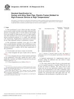
6.3 Charpy Impact Test—Tests shall be made in accordance
with Test Methods E23, except that dimensions of the specimens shall be 0.500 in. (12.70 mm) by full thickness of pipe
wall. Unless otherwise specified by the purchaser, the Charpy
notched impact test specimen shall be in accordance with Fig.
3, except that it may be cut circumferentially. In case of
dispute, the specimen shall be cut in accordance with Fig. 3. If
the pipe wall thickness exceeds 0.40 in. (10.2 mm), the Charpy
impact specimen may be machined to a nominal thickness of
0.40 in. (10.2 mm). In all tests, impact values are to be
corrected to a standard wall thickness, ts = 0.40 in. (10.2 mm),
by calculation as follows:
855 (388)
1040 (472)
1205 (547)
1425 (646)
1710 (776)
2210 (1002)
2955 (1340)
3765 (1708)
4805 (2180)
6035 (2737)
6930 (3143)
7680 (3484)
A
Nominal thickness is based on the minimum Pressure Class ductile iron pipe
available installed in Type 5 trench condition in accordance with ANSI/AWWA
C150/A21.50, as shown in Fig. 1, with a maximum ring deflection of 5 % and
maximum ring stress of 48,000 psi (331 MPa). Wall thickness of pipe to serve at
other depths of cover may be calculated in accordance with ANSI/AWWA
C150/A21.50, allowing 5 % maximum ring deflection.
Impact value ~ corrected! 5
ts
3 impact value ~ actual!
t
where:
t = the thickness of the specimen, in. (mm).
The Charpy impact test machine anvil shall not be moved to
compensate for the variation of cross-section dimensions of the
test specimen.
6.3.1 Acceptance Value—The corrected acceptance value
for notched impact test specimens shall be a minimum of 7
ft·lbf (9.49 J) for tests conducted at 70 6 10°F (21 6 6°C).
6.4 Sampling—At least one tension specimen shall be taken
during each casting period of approximately 3 h. At least one
70 6 10°F (21 6 6°C) Charpy impact specimen shall be taken
during each operating hour. Specimens shall be selected to
properly represent extremes of pipe diameters and wall thicknesses.
7. Additional Control Tests by Manufacturer
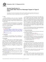
NOTE 1—Pipe is bedded to its centerline in compacted granular material
with a minimum of 4 in. (102 mm) under the pipe. Compacted granular or
selectA material is used to the top of the pipe. (Material is compacted to
approximately 90 % Standard Proctor in accordance with AASHTO
Standard T-99.)
A
Loose soil or select material is defined as native soil excavated from
the trench, free of rocks, foreign material, and frozen earth.
7.1 An additional low-temperature impact test shall be made
from at least 10 % of the sample coupons taken for the required
70 6 10°F (21 6 6°C) Charpy impact test specified in 6.4 to
check compliance with a minimum corrected value of 3 ft·lbf
(4.07 J) for tests conducted at −40°F 6 2°F (−40°C 6 1°C).
Test specimens shall be prepared and tested in accordance with
6.3.
FIG. 1 Type 5 Trench
7.2 In addition, the manufacturer shall conduct such other
tests as may be necessary to ensure compliance with this
specification.
6. Acceptance Tests
6.1 The standard acceptance tests for the physical characteristics of the pipe shall be as follows:
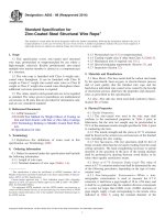
6.2 Tension Test—Unless otherwise specified by the
purchaser, a tension test specimen shall be cut longitudinally or
circumferentially from the midsection of the pipe wall. In case
of dispute, the specimen shall be cut longitudinally. This
specimen shall be machined and tested in accordance with Fig.
2 and Test Methods E8. The yield strength shall be determined
by the 0.2 % offset, halt-of-pointer, or extension-under-load
methods. If check tests are to be made, the 0.2 % offset method
shall be used. All specimens shall be tested at room temperature 70 6 10°F (21 6 6°C).
8. Additional Tests Required by Purchaser
8.1 When tests other than those required in this specification
are required by the purchaser, such tests shall be specified in
the purchaser’s specifications.
9. Inspection and Certification by Manufacturer
9.1 The manufacturer shall establish the necessary qualitycontrol and inspection practice to ensure compliance with this
specification.
2
A716 − 08 (2014)
NOTE 1—The reduced section (A) may have a gradual taper from the ends toward the center with the ends not more than 0.005 in. (0.13 mm) larger
in diameter than the center on the standard specimen and not more than 0.003 in. (0.08 mm) larger in diameter than the center on the small size specimens.
NOTE 2—If desired, on the small size specimens the length of the reduced section may be increased to accommodate an extensometer. However,
reference marks for the measurement of elongation should nevertheless be spaced at the indicated gage length (G).
NOTE 3—The gage length and fillets shall be as shown, but the ends may be of any form to fit the holders of the testing machine in such a way that
the load shall be axial. If the ends are to be held in grips it is desirable, if possible to make the length of the grip section great enough to allow the specimen
to extend into the grips a distance equal to two thirds or more of the length of the grips.
Dimension
G
D
R, min
A, min
TA
A
Standard Specimen
Small-Size Specimens Proportional to Standard
0.50-in (12.7-mm) Round
0.350-in. (8.89-mm) Round
0.250-in. (6.35-mm) Round
2.000 ± 0.005 (50.80 ± 0.13)
0.500 ± 0.010 (12.70 ± 0.25)
3⁄8 (9.5)
21⁄4 (57.2)
0.71 and greater (18.0)
1.400 ± 0.005 (35.56 ± 0.13)
0.350 ± 0.007 (8.89 ± 0.18)
1⁄4 (6.4)
13⁄4 (44.4)
0.50 to 0.70 (12.7 to 17.8)
1.000 ± 0.005 (25.40 ± 0.13)
0.250 ± 0.005 (6.35 ± 0.13)
3⁄16 (4.8)
11⁄4 (31.8)
0.35 ± 0.49 (8.9 to 12.4)
0.175-in. (4.45-mm) Round
0.700 ± 0.005 (17.78± 0.13)
0.175 ± 0.005 (4.44 ± 0.13)
3⁄32 (2.4)
3⁄4 (19)
0.25 to 0.34 (6.4 ± 8.6)
0.125-in. (3.18-mm) Round
0.500 ± 0.005 (12.70 ± 0.13)
0.125 ± 0.005 (3.18 ± 0.13)
3⁄32 (2.4)
5⁄8 (15.9)
0.18 to 0.24 (4.6 to 6.1)
Thickness of the section from the wall of the pipe from which the tension specimen is to be machined.
FIG. 2 Tension-Test Specimen
9.2 The manufacturer shall, if required by the purchaser’s
specifications, furnish a sworn statement that the inspection
and all of the specified tests have been made and that all results
thereof comply with the requirements of this specification.
agreed point of delivery, except as recorded on the delivery
receipt or similar document by the carrier’s agent.
9.3 All pipes shall be without defects that could impair
service. Repairing of defects by welding or other methods shall
not be allowed if such repairs could adversely affect the
serviceability of the pipe or its capability to meet strength
requirements of this specification.
12.1 The results of the acceptance tests (Section 6) and
low-temperature impact tests (Section 7) shall be recorded and
retained for 1 year, and shall be available to the purchaser at the
foundry. Written transcripts shall be furnished, if required by
the purchaser’s specification.
12. Foundry Records
10. Inspection by Purchaser
13. Defective Specimens and Retests
10.1 If the purchaser desires to inspect pipe at the manufacturer’s plant, the purchaser shall so state in the purchaser’s
specifications and describe the conditions (such as time and the
extent of inspection) under which the inspection shall be made.
13.1 When any mechanical-test specimen shows defective
machining or lack of continuity of metal, it shall be discarded
and replaced by another specimen. When any sound test
specimen fails to meet the specified mechanical property
requirements, the lot of pipe from which the specimen was
obtained shall be separated from acceptable pipe. The lot may
be either retested, re-heat treated as necessary and retested, or
rejected. A retest shall be made on two additional sound test
specimens taken from the same lot as the specimen that failed.
Pipe that are re-heat treated or retested, or both, shall meet the
requirements of 4.1, 6, and 7.
10.2 The purchaser’s representative shall have free access to
those areas of the manufacturer’s plant that are necessary to
determine compliance with this standard specification. The
manufacturer shall make available for the use of the purchaser’s representative such gages as are necessary for inspection.
The manufacturer shall provide the purchaser’s representative
with assistance as necessary for handling of pipe.
11. Delivery and Acceptance
14. Rejection of Pipe
11.1 All pipe and accessories shall comply with this standard specification. Pipe and accessories not complying with
this standard specification shall be replaced by the manufacturer at the agreed point of delivery. The manufacturer shall not
be liable for shortages or damaged pipe after acceptance at the
14.1 If the results of any physical acceptance test fail to
meet the requirements of Sections 6, 7, or 13, all pipe cast in
the same period shall be rejected, except as provided in Section
15.
3
A716 − 08 (2014)
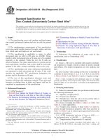
NOTE 1—t = pipe-wall thickness.
in.
(mm)
in.
(mm)
−0.100
+0.000
0.001
0.002
0.010
(−2.54)
(+0.00)
(0.03)
(0.05)
(0.25)
0.100
0.421
0.500
2.165
(2.54)
(10.69)
(12.70)
(54.99)
FIG. 3 Impact Test Specimen
15. Determining Rejection
produced, and the letter “DI” or “DUCTILE” shall be cast or
metal stamped on the pipe and letters and number shall be not
less than 1⁄2 in. (13 mm) in height. When required in the
purchaser’s specifications, initials not exceeding four in number shall be cast or stamped on the pipe. All required markings
shall be clear and legible, and all cast or metal stamped marks
shall be on or near the bell.
15.1 The manufacturer may determine the amount of pipe to
be rejected by making similar additional tests of pipe, of the
same size as the rejected pipe, until the rejected lot is
bracketed, in order of manufacture, by an acceptable test at
each end of the interval in question. When pipe of one size is
rejected from a casting period, the acceptability of pipe of
different sizes from that same period may be established by
developing the acceptance tests for these sizes as specified in
Section 6.
17. Weighing the Pipe
17.1 Each pipe shall be weighed and the weight shown on
the outside or inside of the bell or spigot end.
16. Marking Pipe
18. Keywords
16.1 The weight, class, or nominal thickness, and casting
period shall be shown on each pipe. The manufacturer’s mark,
the country where cast, the year in which the pipe was
18.1 ductile iron culvert pipe; elongation; mechanical properties; tensile strength; yield strength
4
A716 − 08 (2014)
ASTM International takes no position respecting the validity of any patent rights asserted in connection with any item mentioned
in this standard. Users of this standard are expressly advised that determination of the validity of any such patent rights, and the risk
of infringement of such rights, are entirely their own responsibility.
This standard is subject to revision at any time by the responsible technical committee and must be reviewed every five years and
if not revised, either reapproved or withdrawn. Your comments are invited either for revision of this standard or for additional standards
and should be addressed to ASTM International Headquarters. Your comments will receive careful consideration at a meeting of the
responsible technical committee, which you may attend. If you feel that your comments have not received a fair hearing you should
make your views known to the ASTM Committee on Standards, at the address shown below.
This standard is copyrighted by ASTM International, 100 Barr Harbor Drive, PO Box C700, West Conshohocken, PA 19428-2959,
United States. Individual reprints (single or multiple copies) of this standard may be obtained by contacting ASTM at the above
address or at 610-832-9585 (phone), 610-832-9555 (fax), or (e-mail); or through the ASTM website
(www.astm.org). Permission rights to photocopy the standard may also be secured from the Copyright Clearance Center, 222
Rosewood Drive, Danvers, MA 01923, Tel: (978) 646-2600; />
5