Astm b 248m 12
Bạn đang xem bản rút gọn của tài liệu. Xem và tải ngay bản đầy đủ của tài liệu tại đây (196 KB, 13 trang )
Designation: B248M − 12
Standard Specification for
General Requirements for Wrought Copper and CopperAlloy Plate, Sheet, Strip, and Rolled Bar (Metric)1
This standard is issued under the fixed designation B248M; the number immediately following the designation indicates the year of
original adoption or, in the case of revision, the year of last revision. A number in parentheses indicates the year of last reapproval. A
superscript epsilon (´) indicates an editorial change since the last revision or reapproval.
This standard has been approved for use by agencies of the U.S. Department of Defense.
B122/B122M Specification for Copper-Nickel-Tin Alloy,
Copper-Nickel-Zinc Alloy (Nickel Silver), and CopperNickel Alloy Plate, Sheet, Strip, and Rolled Bar
B152/B152M Specification for Copper Sheet, Strip, Plate,
and Rolled Bar
B169/B169M Specification for Aluminum Bronze Sheet,
Strip, and Rolled Bar
B193 Test Method for Resistivity of Electrical Conductor
Materials
B194 Specification for Copper-Beryllium Alloy Plate, Sheet,
Strip, and Rolled Bar
B248 Specification for General Requirements for Wrought
Copper and Copper-Alloy Plate, Sheet, Strip, and Rolled
Bar
B422 Specification for Copper-Aluminum-Silicon-Cobalt
Alloy, Copper-Nickel-Silicon-Magnesium Alloy, CopperNickel-Silicon Alloy, Copper-Nickel-AluminumMagnesium Alloy, and Copper-Nickel-Tin Alloy Sheet
and Strip
B465 Specification for Copper-Iron Alloy Plate, Sheet, Strip,
and Rolled Bar
B534 Specification for Copper-Cobalt-Beryllium Alloy and
Copper-Nickel-Beryllium Alloy Plate, Sheet, Strip, and
Rolled Bar
B591 Specification for Copper-Zinc-Tin and Copper-ZincTin-Iron-Nickel Alloys Plate, Sheet, Strip, and Rolled Bar
B592 Specification for Copper-Zinc-Aluminum-Cobalt
Alloy, Copper-Zinc-Tin-Iron Alloy Plate, Sheet, Strip, and
Rolled Bar
B694 Specification for Copper, Copper-Alloy, Copper-Clad
Bronze (CCB), Copper-Clad Stainless Steel (CCS), and
Copper-Clad Alloy Steel (CAS) Sheet and Strip for
Electrical Cable Shielding
B740 Specification for Copper-Nickel-Tin Spinodal Alloy
Strip
B747 Specification for Copper-Zirconium Alloy Sheet and
Strip
B768 Specification for Copper-Cobalt-Beryllium Alloy and
Copper-Nickel-Beryllium Alloy Strip and Sheet
B846 Terminology for Copper and Copper Alloys
1. Scope*
1.1 This specification establishes the general requirements
common to several wrought product specifications. Unless
otherwise specified in the purchase order or in an individual
specification, these general requirements shall apply to copper
and copper-alloy plate, sheet, strip, and rolled bar supplied
under each of the following product specifications issued by
ASTM: B36/B36M, B96/B96M, B103/B103M, B121/B121M,
B122/B122M, B152/B152M, B169/B169M, B194, B422,
B465, B534, B591, B592, B694, B740, B747, B768, and
B888.2
1.2 Units—This specification is the companion specification
to inch-pound Specification B248.
2. Referenced Documents
2.1 The following documents of the issue in effect on date
of material purchase form a part of this specification to the
extent referenced herein:
2.2 ASTM Standards:3
B36/B36M Specification for Brass Plate, Sheet, Strip, And
Rolled Bar
B96/B96M Specification for Copper-Silicon Alloy Plate,
Sheet, Strip, and Rolled Bar for General Purposes and
Pressure Vessels
B103/B103M Specification for Phosphor Bronze Plate,
Sheet, Strip, and Rolled Bar
B121/B121M Specification for Leaded Brass Plate, Sheet,
Strip, and Rolled Bar
1
This specification is under the jurisdiction of ASTM Committee B05 on Copper
and Copper Alloys and is the direct responsibility of Subcommittee B05.01 on Plate,
Sheet, and Strip.
Current edition approved April 1, 2012. Published May 2012. Originally
approved in 1980. Last previous edition approved in 2007 as B248M – 07. DOI:
10.1520/B0248M-12.
2
The UNS system for copper and copper alloys (see Practice E527) is a simple
expansion of the former standard designation system accomplished by the addition
of a prefix “C” and a suffix “00.” The suffix can be used to accommodate
composition variations of the base alloy.
3
For referenced ASTM standards, visit the ASTM website, www.astm.org, or
contact ASTM Customer Service at For Annual Book of ASTM
Standards volume information, refer to the standard’s Document Summary page on
the ASTM website.
*A Summary of Changes section appears at the end of this standard
Copyright © ASTM International, 100 Barr Harbor Drive, PO Box C700, West Conshohocken, PA 19428-2959. United States
1
B248M − 12
4.1.1 The material of manufacture shall be a cast bar, cake,
slab of such purity and soundness as to be suitable for
processing into the products to the product specification listed
in Section 1.
4.1.2 When specified in the contract or purchase order that
the heat identification or traceability is required, the purchaser
shall specify the details desired.
B888 Specification for Copper Alloy Strip for Use in Manufacture of Electrical Connectors or Spring Contacts
E8/E8M Test Methods for Tension Testing of Metallic Materials
E18 Test Methods for Rockwell Hardness of Metallic Materials
E29 Practice for Using Significant Digits in Test Data to
Determine Conformance with Specifications
E50 Practices for Apparatus, Reagents, and Safety Considerations for Chemical Analysis of Metals, Ores, and
Related Materials
E53 Test Method for Determination of Copper in Unalloyed
Copper by Gravimetry
E54 Test Methods for Chemical Analysis of Special Brasses
and Bronzes (Withdrawn 2002)4
E62 Test Methods for Chemical Analysis of Copper and
Copper Alloys (Photometric Methods) (Withdrawn 2010)4
E75 Test Methods for Chemical Analysis of Copper-Nickel
and Copper-Nickel-Zinc Alloys (Withdrawn 2010)4
E106 Test Methods for Chemical Analysis of CopperBeryllium Alloys (Withdrawn 2011)4
E112 Test Methods for Determining Average Grain Size
E118 Test Methods for Chemical Analysis of CopperChromium Alloys (Withdrawn 2010)4
E121 Test Methods for Chemical Analysis of CopperTellurium Alloys (Withdrawn 2010)4
E255 Practice for Sampling Copper and Copper Alloys for
the Determination of Chemical Composition
E478 Test Methods for Chemical Analysis of Copper Alloys
E527 Practice for Numbering Metals and Alloys in the
Unified Numbering System (UNS)
4.2 Manufacture:
4.2.1 The product shall be manufactured by such hot
working, cold working and annealing process as to produce a
uniform wrought structure in the finished product.
4.2.2 The product shall be hot or cold worked to the finished
size and subsequently annealed when required, to meet the
temper properties specified.
4.3 Edges—The edges shall be slit, shared, sawed, or rolled
edges, as specified. Slit edges shall be furnished unless
otherwise specified in the contract or purchase order. See 5.6
for edge descriptions and corresponding tables for tolerances.
5. Dimensions, Mass, and Permissible Variations
5.1 General—For the purpose of determining conformance
with the dimensional requirements prescribed in this
specification, any measured value outside the specified limiting
values for any dimension may be cause for rejection.
NOTE 1—Blank spaces in the tolerance tables indicate either that the
material is not available or that no tolerances have been established.
5.2 Thickness—The standard method of specifying thickness shall be in decimal fractions of a millimetre. For material
0.50 mm and under in thickness, it is recommended that the
nominal thicknesses be stated not closer than the nearest 0.01
mm. A list of preferred thicknesses is shown in Appendix X1.
The thickness tolerances shall be those shown in Tables 1-3 for
the product specification indicated:
5.2.1 Table 1—Thickness tolerances applicable to Specifications B36/B36M, B103/B103M, B121/B121M, B152/
B152M, B465, B591, B592, B747, and B888.
5.2.2 Table 2—Thickness tolerances applicable to Specifications B96/B96M, B122/B122M, B169/B169M, B194, B422,
B534, B740, and B768.
5.2.3 Table 3—Special thickness tolerances applicable to
Copper Alloy UNS No. C72500 when ordered to Specification
B122/B122M, and to Specifications B194, B534, B740, and
B768 as noted in the table.
3. Terminology
3.1 For definitions of terms related to copper and copper
alloys, refer to Terminology B846.
3.2 Definitions of Terms Specific to This Standard:
3.2.1 coil, n—a length of the product wound into a series of
connected turns. The unqualified term “coil” as applied to “flat
product” usually refers to a coil in which the product is spirally
wound, with the successive layers on top of one another.
(Sometimes called a “roll.”)
3.2.2 lengths, mill, n—straight lengths, including ends, that
can be conveniently manufactured in the mills. Full length
pieces are usually 2400, 3000, or 3600 mm and subject to
established length tolerances.
3.2.2.1 lengths, stock, n—straight lengths that are mill cut
and stored in advance of orders. They are usually 2400, 3000,
or 3600 mm and subject to established length tolerances.
3.2.3 rolled bar, n—a rolled flat product over 5 mm thick
and up to and including 300 mm wide, with sheared, sawed, or
machined edges, in straight lengths or coils (rolls).
5.3 Width—The width tolerances shall be those shown in
Tables 4-6 depending on the type of edge required (see 5.3.1,
5.3.2, and 5.3.3):
5.3.1 Table 4—Width tolerances for slit metal and slit metal
with rolled edges.
5.3.2 Table 5—Width tolerances for square-sheared metal.
5.3.3 Table 6—Width tolerances for sawed metal.
5.4 Length—The material shall be furnished in coils or
straight lengths of plate, sheet, strip, or rolled bar as specified.
The length tolerances for straight lengths shall be those shown
in Tables 7-10 depending on the method of cutting required
(see 5.4.1 – 5.4.4). When ends are permitted, the length and
quantity of the ends shall be in accordance with the schedule in
Table 8.
4. Materials and Manufacture
4.1 Materials:
4
The last approved version of this historical standard is referenced on
www.astm.org.
2
B248M − 12
TABLE 1 Thickness Tolerances
(Applicable to Specifications B36/B36M, B103/B103M, B121/B121M, B152/B152M, B465, B591, B592, B747 and B888)
Thickness, mm
Thickness Tolerances, Plus and Minus, mm
Strip
Sheet
Over
Through
Up to 200
mm, incl, in
Width
Over 200
mm to 300
mm, incl, in
Width
Over 300
mm to 600
mm, incl, in
Width
Over 600
mm to 700
mm, incl, in
Width
Over 700
mm to 900
mm, incl, in
Width
Over 900
mm to 1200
mm, incl, in
Width
Over 1200
mm to 1600
mm, incl, in
Width
0.10
0.20
0.30
0.40
0.50
0.60
0.70
1.0
1.3
2.0
3.5
0.10
0.20
0.30
0.40
0.50
0.60
0.70
1.0
1.3
2.0
3.5
5.0
0.007
0.01
0.015
0.02
0.025
0.03
0.035
0.045
0.05
0.06
0.07
0.08
0.015
0.02
0.025
0.03
0.035
0.04
0.05
0.05
0.06
0.07
0.08
0.10
...
0.03
0.035
0.045
0.05
0.05
0.06
0.06
0.07
0.08
0.10
0.11
...
...
...
0.06
0.06
0.08
0.08
0.09
0.10
0.12
0.15
.17
...
...
...
0.08
0.08
0.09
0.09
0.10
0.12
0.15
0.17
0.20
Plate
0.25
0.35
0.45
0.55
0.65
0.75
...
...
...
0.09
0.09
0.10
0.10
0.12
0.15
0.17
0.20
0.25
...
...
...
0.10
0.11
0.12
0.12
0.15
0.17
0.20
0.25
0.30
0.11
0.12
0.17
0.22
0.55
0.65
0.12
0.15
0.22
0.27
0.55
0.65
0.22
0.30
0.40
0.45
0.55
0.65
0.30
0.40
0.50
0.60
0.75
0.90
0.35
0.45
0.60
0.75
0.90
1.1
Rolled Bar
5.0
8.0
13.0
20.0
30.0
40.0
8.0
13.0
20.0
30.0
40.0
60.0
0.10
0.11
0.13
0.17
0.55
0.65
TABLE 2 Thickness Tolerances
(Applicable to Specifications B96/B96M, B122/B122M, B169/B169M, B194, B422, B534, B740, and B768)
Thickness, mm
Thickness Tolerances, Plus and Minus, mm
Strip
Sheet
Over
Through
Up to 200
mm, incl, in
Width
Over 200
mm to 300
mm, incl, in
Width
Over 300
mm to 600
mm, incl, in
Width
Over 600
mm to 700
mm, incl, in
Width
Over 700
mm to 900
mm, incl, in
Width
Over 900
mm to 1200
mm, incl, in
Width
Over 1200
mm to 1600
mm, incl, in
Width
0.10
0.20
0.30
0.40
0.50
0.60
0.70
1.0
1.3
2.0
3.5
0.10
0.20
0.30
0.40
0.50
0.60
0.70
1.0
1.3
2.0
3.5
5.0
0.01
0.015
0.02
0.025
0.03
0.035
0.05
0.06
0.07
0.08
0.10
0.11
0.02
0.025
0.03
0.035
0.05
0.06
0.06
0.07
0.08
0.10
0.11
0.13
...
0.035
0.05
0.06
0.06
0.07
0.07
0.08
0.10
0.11
0.12
0.15
...
...
...
...
...
...
0.10
0.13
0.15
0.18
0.20
0.25
...
...
...
...
...
...
0.13
0.15
0.18
0.20
0.25
0.30
Plate
0.35
0.45
0.55
0.65
0.80
0.95
...
...
...
...
...
...
0.15
0.18
0.20
0.25
0.30
0.35
...
...
...
...
...
...
0.18
0.20
0.25
0.30
0.35
0.40
0.15
0.18
0.25
0.40
0.70
0.85
0.18
0.20
0.30
0.50
0.70
0.85
0.30
0.40
0.50
0.60
0.70
0.85
0.40
0.50
0.60
0.75
0.95
1.1
0.45
0.60
0.75
0.95
1.2
1.4
Rolled Bar
5.0
8.0
13.0
20.0
30.0
40.0
8.0
13.0
20.0
30.0
40.0
60.0
0.13
0.15
0.20
0.30
0.70
0.85
portion of the total length, shall be those shown in Tables 11-13
depending on the type of edge required.
5.5.1 Table 11—Straightness tolerances for metal as slit, or
as slit and straightened, or as slit and edge-rolled, or metal with
drawn edges.
5.5.2 Table 12—Straightness tolerances for square-sheared
metal.
5.5.3 Table 13—Straightness tolerances for sawed metal.
5.4.1 Table 7—Length tolerances for straight lengths.
5.4.2 Table 8—Schedule of minimum length and maximum
weight of ends for mill lengths, specific lengths with ends, and
stock lengths with ends.
5.4.3 Table 9—Length tolerances for square-sheared metal
in all widths 3000 mm and under.
5.4.4 Table 10—Length tolerances for sawed metal.
5.5 Straightness—The straightness tolerances which are the
maximum edgewise curvature (depth of arc) in any 1800-mm
3
B248M − 12
TABLE 3 Special Thickness Tolerances
Thickness, mm
0.10 and under
Over 0.10 to 0.16, incl
Over 0.016 to 0.22, incl
Over 0.22 to 0.35, incl
Over 0.35 to 0.45, incl
Over 0.45 to 0.55, incl
Over 0.55 to 0.60, incl
Over 0.65 to 0.80, incl
Over 0.80 to 1.2, incl
A
Tolerances Applicable to Copper Alloy
UNS No. C72500,
Specifications
B122/B122M
Tolerances,
Plus and
Minus,A mm for
Strip 200 mm and
Under in Width
Tolerances Applicable to Specifications
B194, B534, B740, and
B768 Tolerances, Plus
and Minus,A mm
for Strip 100 mm
and Under in
Width
0.005
0.008
0.010
0.013
0.018
0.020
0.025
0.033
0.038
0.005
0.008
0.013
0.015
0.018
0.020
0.025
0.025
...
7.1.1 Lot Size—An inspection lot shall be 5000 kg or less
material of the same mill form, alloy, temper and nominal
dimensions, subject to inspection at one time, or shall be the
product of one cast bar from a single melt charge, whose
weight shall not exceed 12 000 kg that has been continuously
processed and subject to inspection at one time.
7.1.2 Portion Size—A portion shall be two representative
samples taken from the product of one cast bar that has been
continuously processed to the finished temper and dimensions.
7.1.2.1 Chemical Analysis—A sample for chemical analysis
shall be taken in accordance with Practice E255 for product in
its final form. Unless required otherwise by the purchaser at the
time the order is placed, the manufacturer shall have the option
of determining conformance to chemical composition by
analyzing samples taken at the time the castings are poured or
samples taken from the semi-finished product, if heat identity
can be maintained throughout all operations. If the manufacturer determines the chemical composition of the material
during the course of manufacture, he shall not be required to
sample and analyze the finished product. The minimum weight
of the composite sample in accordance with Practice E255
shall be as follows:
If tolerances are specified as all plus or all minus, double the values given.
5.6 Edges—When rolled edges are required, they may be
produced by either rolling or drawing to one of the following
specified edge contours:
5.6.1 Square Edges (Square Corners)—Edges shall have
commercially-squared corners with a permissible maximum
radius as prescribed in Table 14.
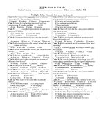
5.6.2 Rounded Corners—Edges shall have rounded corners
as shown in Fig. 1 with a radius as prescribed in Table 15.
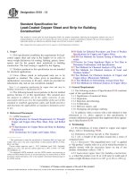
5.6.3 Rounded Edges—Edges shall be rounded as shown in
Fig. 2 with a radius as prescribed in Table 16.
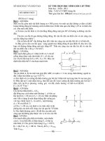
5.6.4 Full-Rounded Edges—Edges shall be full-rounded as
shown in Fig. 3 with a radius as prescribed in Table 17.
ASTM Designation
B36/B36M, B96/B96M, B103/B103M, B121/B121M,
B122/B122M, B152/B152M, B169/B169M, B194, B422,
B465, B534, B591, B592,B740, B747,
B768, and B888
Weight of
Sample,
min, g
150
7.1.2.2 Samples for All Other Tests—Samples for all other
tests shall be taken from the sample portion in 7.1.2 and be of
a convenient size to accommodate the test and comply with the
requirements of the appropriate ASTM standard and test
methods.
5.7 Weight Tolerances for Hot-Rolled Material:
5.7.1 Table 18—Lot weight tolerances for hot-rolled sheet
and plate applicable to Specifications B36/B36M, B96/B96M
(Copper Alloy UNS No. C65500), B103/B103M, B122/
B122M, B152/B152M, and B591.
5.7.2 The weight of each lot of five or more plates or sheets
of the same type and the same specified dimensions, when
ordered to thickness, shall not vary from the theoretical by
more than the amount prescribed in Table 18 for the product
specification indicated. The weight of any individual plate or
sheet may vary from the nominal by not more than one third in
excess of the tolerances prescribed in Table 18 for the product
specification indicated. The tolerances for lots of less than five
plates or sheets shall be governed by the tolerances for
individual plates or sheets.
5.7.3 For the purpose of calculation, the densities of the
materials covered by these specifications are listed in Appendix
X2.
8. Number of Tests and Retests
8.1 Chemical Requirements:
8.1.1 When samples are taken at the time the castings are
poured, at least one sample shall be analyzed for each group of
castings poured simultaneously from the same source of
molten metal.
8.1.2 When samples are taken from the semi-finished or
finished product, at least one sample representative of the
product of each cast bar from a single melt charge continuously
processed with heat identity maintained shall be analyzed.
8.1.3 When samples are taken from the semi-finished or
finished product and heat identity has not been maintained, a
single sample representative of each 5000-kg lot, or fraction
thereof, shall be analyzed. When the product piece is greater
than 5000 kg, one sample to be representative of the product
piece shall be analyzed.
6. Workmanship, Finish, and Appearance
6.1 The product shall be free of defects, but blemishes of a
nature that do not interfere with the intended application are
acceptable. A superficial film of residual light lubricant is
normally present and is acceptable unless otherwise specified.
8.2 Mechanical and Electrical Requirements and Grain
Size—Unless otherwise provided in the product specification,
test specimens shall be taken from each of the two sample
pieces selected in accordance with 7.1.2. The required tests
shall be made on each of the specimens. In the case of copper
alloy Specifications B194, B534, and B740, one specimen shall
be tested without further treatment, and the other specimen
shall be tested after precipitation hardening. In the case of the
7. Sampling
7.1 Sampling—The lot size, portion size, and selection of
sample pieces shall be as follows:
4
B248M − 12
TABLE 4 Width Tolerances for Slit Metal and Slit Metal with Rolled Edges
(Applicable to all specifications listed in 1.1)
Width Tolerances,A Plus and Minus, mm
A
Width, mm
For Thicknesses
0.102 to 0.80 mm, incl
For Thicknesses
Over 0.80 to 3.2 mm, incl
For Thicknesses
Over 3.2 to 5.0 mm, incl
For Thicknesses
Over 5.0 to 12.0 mm, incl
50.8 and under
Over 50.8 to 200, incl
Over 200 to 600, incl
Over 600 to 1270, incl
0.13
0.20
0.40
0.79
0.25
0.33
0.40
0.79
0.30
0.38
0.40
0.79
0.38
0.38
0.79
1.19
If tolerances are specified as all plus or all minus, double the values given.
TABLE 5 Width Tolerances for Square-Sheared Metal
(Applicable to all specifications listed in 1.1)
conform to the specified limits, analysis shall be made on a
new composite sample prepared from the samples selected in
accordance with 7.1.2.
8.3.2 If one of the two tests made to determine any of the
mechanical or physical properties fails to meet a specified
limit, this test shall be repeated on the remaining sample
pieces, selected in accordance with 7.1.2 and the results of
these tests shall comply with the specified requirements.
8.3.3 If any test specimen shows defective machining or
develops flaws, it may be discarded and another specimen
substituted.
8.3.4 If the percent elongation of any tension test specimen
is less than that specified and any part of the fracture is outside
the middle two thirds of the gage length or in a punched or
scribed mark within the reduced section, a retest shall be
allowed.
8.3.5 If a bend test specimen fails, due to conditions of
bending more severe than required by the specification, a retest
shall be permitted, either on a duplicate specimen or on a
remaining portion of the failed specimen.
8.3.6 After removal of defective specimens and correction
of test methods, only one retest cycle is permitted. If after the
retest the material fails to meet the requirements of this
specification, it shall be rejected.
NOTE 1—All lengths up to 3.05 m, inclusive.
Width, mm
500 and under
Over 500 to 900, incl
Over 900 to 3000, incl
A
Width Tolerances,A Plus and Minus, mm
1.59 mm
Over 1.5 mm
Over 3.5
and Under
to 3.5 mm,
mm in
in Thickincl, in
Thickness
ness
Thickness
0.79
1.2
1.6
1.2
1.2
1.6
1.6
1.6
1.6
If tolerances are specified as all plus or all minus, double the values given.
TABLE 6 Width Tolerances for Sawed Metal
(Applicable to all specifications listed in 1.1)
Width, mm
Up to 300, incl
Over 300 to 3000, incl
A
Width Tolerances,A Plus and Minus, mm
For Lengths Up to
For Length Over
3000 mm, incl
3000 mm
For ThickFor Thicknesses Up
All Thicknesses Over
to 38 mm,
nesses
38.1 mm
incl
0.79
1.6
1.6
1.6
1.6
1.6
If tolerances are specified as all plus or all minus, double the values given.
TABLE 7 Length Tolerances for Straight Lengths
(Applicable to all specifications listed in 1.1 except B694)
9. Specimen Preparation
NOTE 1—The following length tolerances are all plus: if all minus
tolerances are desired, use the same values; if tolerances are desired plus
and minus, halve the values given.
Length, mm
Specific lengths, mill lengths, multiple lengths, and specific
lengths with ends
3000 and under
Over 3000 to 6000, incl
Stock lengths and stock lengths with ends
9.1 Chemical Analysis—A composite sample of the semifinished or finished product shall be prepared in accordance
with Practice E255 or as described in 7.1.2.1.
Length Tolerances, mm
9.2 Specimens shall be prepared in accordance with the
method prescribed in 10.3 for all other tests. Full cross section
specimens shall be used whenever possible. Samples shall be
representative of the condition of the material, and particular
specimen preparation techniques shall be stated in the specific
product specification.
6.4
13
25A
A
As stock lengths are cut and placed in stock in advance of orders, departure from
this tolerance is not practicable.
10. Test Methods
requirements in Table 4, Mill Hardened Tempers, in Specifications B194 and B740, the two specimens need to be tested,
because the product is in the precipitation hardened temper as
supplied. The reported value shall be the arithmetic average of
the readings. In the case of hardness, three readings shall be
taken and averaged for each sample.
10.1 The test method used for routine chemical analysis for
specification compliance and preparation of certifications and
test reports, when required, shall be at the discretion of the
reporting laboratory.
10.1.1 Commonly accepted technique for routine chemical
analysis of copper and copper alloys include, but are not
limited to, X-ray fluorescence spectroscopy, atomic absorption
spectrophotometry, argon plasma spectroscopy, and emission
spectroscopy.
8.3 Retests:
8.3.1 If the chemical analysis of the specimens prepared
from samples selected in accordance with 7.1.2 fails to
5
B248M − 12
TABLE 8 Schedule of Minimum Length and Maximum Weight of Ends for Mill Lengths, Specific Lengths with Ends,
and Stock Lengths with Ends
(Applicable to all specifications listed in 1.1 except B694)
1.3 mm and Under in
Thickness
Minimum
Maximum
Length of
Permissible
Shortest
Weight of
Piece, mm
Ends, % of
Lot Weight
1200
20
1800
25
2000
30
Nominal
Length, mm
1800 to 2400, incl
2400 to 3000, incl
3000 to 4300, incl
Over 1.3 to 3.2 mm, incl, in
Thickness
Minimum
Maximum
Length of
Permissible
Shortest
Weight of
Piece, mm
Ends, % of
Lot Weight
1200
25
1500
30
1800
35
TABLE 9 Length Tolerances for Square-Sheared Metal in All
Widths 3000 mm and Under
(Applicable to all specifications listed in 1.1 except B694)
508 and under
Over 508 to 914, incl
Over 914 to 3048, incl
A
TABLE 12 Straightness Tolerances for Square-Sheared Metal
(Applicable to all specifications listed in 1.1)
(Not applicable to metal over 3000 mm in length)
Length Tolerance,A Plus and Minus, mm
For ThickFor ThickFor Thicknesses Up
nesses Over
nesses Over
to 1.6 mm,
1.6 to 3.2
3.2mm
incl
mm, incl
0.8
1.2
1.6
1.2
1.2
1.6
1.6
1.6
1.6
Length, mm
Maximum Edgewise Curvature (Depth of Arc) in any
1800-mm Portion of the Total Length
Straightness Tolerances, mm
Up to 250
Over 250
Thickness, mm
mm, incl, in
mm in
Width
Width
3.2 and under
1.6
0.79
Over 3.2 to 5.0, incl
3.2
1.2
Over 5.0
3.2
1.6
If tolerances are specified as all plus or all minus, double the values given.
TABLE 13 Straightness Tolerances for Sawed Metal
(Applicable to all specifications listed in 1.1)
(Not applicable to metal over 3600 mm in length)
TABLE 10 Length Tolerances for Sawed Metal
(Applicable to all specifications listed in 1.1 except B694)
NOTE 1—The following tolerances are all plus; if all minus tolerances
are desired, use the same values; if tolerances are desired plus and minus,
halve the values given.
Width, mm
Up to 3000, incl
Maximum Edgewise Curvature (Depth of Arc) in Any
2000-mm Portion of the Total Length
Width, mm
Straightness Tolerances, mm
80 and under
1.6
Over 80
1.2
Length Tolerance, mm
64
TABLE 14 Tolerances for Radius of Commercially Square
Corners of Rolled or Drawn Edges with Square Corners
(Applicable to all specifications listed in 1.1 except B694)
TABLE 11 Straightness Tolerances for Slit Metal or Slit Metal
Either Straightened or Edge-Rolled
(Applicable to all specifications listed in 1.1)
Maximum Edgewise Curvature (Depth of Arc) in any 1800-mm Portion of the
Total Length
Thickness, mm
As Slit and Either
Straightened
or Edge Rolled
Width, mm
Over
Over
Over
Over
Over
Over
6 to 10, incl
10 to 12, incl
12 to 25, incl
25 to 50, incl
50 to 100, incl
100
Shipped in
Rolls
Shipped
Flat
Shipped Flat,
in Rolls, or on
Bucks
51
38
25
16
13
9.5
38
25
19
16
13
9.5
13
13
13
9.5
9.5
9.5
Permissible Radius of
Corners, max, mm
0.8 to 1.6, incl
Over 1.6 to 4.8, incl
Over 4.8 to 25, incl
Straightness Tolerance, mm
As Slit Only
Over 3.2 to 6.5 mm, incl, in
Thickness
Minimum
Maximum
Length of
Permissible
Shortest
Weight of
Piece, mm
Ends, % of
Lot Weight
900
30
1200
35
1500
40
0.25
0.40
0.8
10.3 The following test methods shall be used for determining the mechanical and physical properties required in the
specifications listed in Section 1:
Tension
Grain size
Rockwell hardness
Electrical resistivity
E8/E8M
E112
E18
B193
10.3.1 The testing procedure used for a particular property
is dependent upon alloy, temper, and configuration of the
product. The manufacturer shall have the option of selecting
the most representative procedure unless a specific procedure is
specified at the time the contract is placed.
10.2 In case of disagreement concerning chemical
composition, an applicable test method for chemical analysis
may be found in Test Methods E53, E54, E62, E75, E106,
E118, E121, or E478.
10.2.1 The specific test method(s) to be used shall be stated
in the particular product specification.
10.2.2 In case of disagreement concerning sulfur content,
the test method described in the Annex shall be used.
11. Significance of Numerical Limits
11.1 For the purposes of determining compliance with the
specified limits for requirements of the properties listed in the
following table and for dimensional tolerances, an observed
6
B248M − 12
TABLE 16 Tolerances for Radius of Rolled or Drawn
Rounded Edges
(Applicable to all specifications listed in 1.1 except B694)
Thickness, mm
Min
1⁄ 4 t
1t
Up to 4.78, incl
Over 4.78
A
Radius of EdgesA
Max
13⁄ 4 t
1 1⁄ 2 t
The t refers to the measured thickness of the test specimen.
NOTE 1—The arc of the rounded corner shall not necessarily be tangent
at points “ A,” but the product shall be commercially free from sharp,
rough, or projecting edges.
FIG. 1 Rounded Corners
TABLE 15 Tolerances for Radius on Corners of Rolled or Drawn
Edges with Rounded Corners
(Applicable to all specifications listed in 1.1 except B694)
Thickness, mm
Up to 3.2, inclA
Over 3.2 to 4.8, incl
Over 4.8 to 25, incl
Over 25 to 50, incl
A
NOTE 1—The arc of the rounded edge shall not necessarily be tangent
at points “ A” but shall be substantially symmetrical with the axis of the
product, and the product shall be commercially free from sharp, rough, or
projecting edges.
Radius of Corners, mm
Min
Max
...
0.40
0.80
1.6
...
1.2
2.4
4.8
FIG. 3 Full Rounded Edge
TABLE 17 Tolerances for Radius of Rolled or Drawn FullRounded Edges
(Applicable in all specifications listed in 1.1)
Not available.
Thickness, mm
All thicknesses
A
FIG. 2 Rounded Edge
value or a calculated value shall be rounded as indicated in
accordance with the rounding method of Practice E29:
Radius of EdgesA
Max
3 ⁄4 t
The t refers to the thickness of the test specimen.
Property
NOTE 1—The arc of the rounded edge shall be substantially symmetrical with the axis of the product. The corners “A” will usually be sharp but
shall not have rough or projecting edges.
Min
1⁄ 2 t
Rounded Unit for Observed or
Calculated Value
Chemical composition
Hardness
Electrical resistivity
Electrical conductivity
nearest unit in the last
right-hand significant digit
used in expressing
the limiting value
Tensile strength
Yield strength
nearest 5 MPa
nearest 5 MPa
Elongation:
nearest 1 %
Grain size:
Under 0.060 mm
0.060 mm and over
nearest multiple of 0.005 mm
nearest 0.01 mm
12. Inspection
12.1 The manufacturer or supplier shall inspect and make
tests necessary to verify that furnished product conforms to the
specification requirements.
12.2 Source inspection of the product by the purchaser may
be agreed upon between the manufacturer, or supplier, and the
7
B248M − 12
TABLE 18 Lot Weight Tolerances for Hot-Rolled Sheet and Plate
(Applicable to Specifications B36/B36M, B96/B96M (Copper Alloy UNS Nos. C65500), B103/B103M, B122/B122M, B152/B152M, and B591)
Weight Tolerances, Plus and Minus, Percentage of Theoretical Weight
Thickness, mm
1200 mm and
Under in Width
Over 1200 to
1500 mm, incl,
in Width
Over 1500 to
1800 mm, incl,
in Width
Over 1800 to
2200 mm, incl,
in Width
Over 2200 to
2800 mm, incl,
in Width
3.18 and under
Over 3.18 to 4.78, incl
Over 4.78 to 6.35, incl
Over 6.35 to 7.92, incl
Over 7.92 to 9.53, incl
Over 9.53 to 11.1, incl
Over 11.1 to 12.7, incl
Over 12.7 to 15.9, incl
Over 15.9 to 19.1, incl
Over 19.1 to 25.4, incl
Over 25.4 to 38.1, incl
Over 38.1 to 50.8, incl
8
6.5
6
5.5
5
4.5
4
3.5
3
2.75
2.5
2.25
9.5
8
7.5
7
6
5
4.5
4.5
4
3.5
3
2.75
11
9.5
8.5
8
7
6
5.5
5
4.5
4
3.5
3.25
12.5
11
9
8.5
7.5
7
6
5.5
5
4.5
4
3.75
14
12.5
10
9
8
7.5
6.5
6
5.5
5
4.5
4.25
purchaser as part of the purchase order. In such case, the nature
of the facilities needed to satisfy the inspector, representing the
purchaser that the product is being furnished in accordance
with the specification, shall be included in the agreement. All
testing and the inspection shall be conducted so as not to
interfere unnecessarily with the operation of the works.
14.2 When specified in the purchase order or contract that
the product is purchased for ASME Boiler and Pressure Vessel
Code applications, certification to this specification is mandatory.
15. Test Report
15.1 When specified in the contract or purchase order, a
report of test results shall be furnished.
12.3 When mutually agreed upon, the manufacturer, or
supplier, and the purchaser shall conduct the final inspection
simultaneously.
16. Product Identification
16.1 For ASME Boiler and Pressure Vessel Code
applications, the name or trademark of the manufacturer and
the manufacturer’s lot identification number shall be legibly
stamped or stenciled on each finishing plate and sheet in two
places not less than 300 mm from the edge. If the plate and
sheet are too small to locate the markings as such, the marking
may be placed near the center of the plate and sheet. In the case
of butt straps, the markings may be placed 300 mm from the
end. The plate number and type shall be legibly stamped on
each plate and on each test specimen.
13. Rejection and Rehearing
13.1 Rejection:
13.1.1 Product that fails to conform to the specification
requirements when tested by the purchaser or purchaser’s agent
shall be subject to rejection.
13.1.2 Rejection shall be reported to the manufacturer or
supplier promptly. In addition, a written notification of rejection shall follow.
13.1.3 In case of dissatisfaction with the results of the test
upon which rejection is based, the manufacturer or supplier
shall have the option to make claim for rehearing.
17. Packaging and Package Marking
17.1 Packaging:
17.1.1 The product shall be separated by size, composition,
and temper, and prepared for shipment by common carrier, in
such a manner to afford protection from the normal hazards of
transportation.
13.2 Rehearing:
13.2.1 As a result of product rejection, the manufacturer, or
supplier, shall have the option to make claim for a retest to be
conducted by the manufacturer, or supplier, and the purchaser.
Samples of the rejected product shall be taken in accordance
with the product specification and subjected to test by both
parties using the test method(s) specified in the product
specification, or alternately, upon agreement of both parties, an
independent laboratory may be selected for the test(s) using the
test method(s) specified in the product specification.
17.2 Package Marking:
17.2.1 Each shipping unit shall be legibly marked with the
purchase order number, metal or alloy designation, temper,
size, shape, gross and net weight, and name of supplier.
17.2.2 When specified in the contract or purchase order, the
product specification number shall be shown.
14. Certification
18. Keywords
14.1 When specified in the purchase order or contract, the
purchaser shall be furnished certification that samples representing each lot have been either tested or inspected as directed
in this specification and requirements have been met.
18.1 general requirements, plate; general requirements,
rolled bar; general requirements, sheet; general requirements,
strip; general requirements, wrought copper and copper alloys
8
B248M − 12
SUPPLEMENTARY REQUIREMENTS
The following supplementary requirements shall apply only when specified by the purchaser in the
inquiry, contract, or order, for agencies of the U.S. government.
unless disapproved by the purchaser at the time the order is
placed. The purchaser shall have the right to perform any of the
inspections and tests set forth when such inspections and tests
are deemed necessary to assure that the material conforms to
prescribed requirements.
S1. Referenced Documents
S1.1 The following documents of the issue in effect on date
of material purchase form a part of this specification to the
extent referenced herein:
S1.1.1 ASTM Standards:
B900 Practice for Packaging of Copper and Copper Alloy
Mill Products for U.S. Government Agencies3
S1.1.2 Federal Standards:5
Fed. Std. No. 102 Preservation, Packaging and Packing
Levels
Fed. Std. No. 123 Marking for Shipment (Civil Agencies)
Fed. Std. No. 185 Identification Marking of Copper and
Copper-Base Alloy Mill Products
S1.1.3 Military Standards:5
MIL-STD-129 Marking for Shipment and Storage
S3. Identification Marking
S3.1 All material shall be properly marked for identification
in accordance with Fed. Std. No. 185 except that the ASTM
specification number and the alloy number shall be used.
S4. Preparation for Delivery
S4.1 Preservation, Packaging, Packing:
S4.1.1 Military Agencies—The material shall be separated
by size, composition, grade or class and shall be preserved and
packaged, Level A or C, packed, Level A, B, or C, as specified
in the contract or purchase order, in accordance with the
requirements of Practice B900.
S4.1.2 Civil Agencies— The requirements of Fed. Std. No.
102 shall be referenced for definitions of the various levels of
packaging protection.
S4.2 Marking:
S4.2.1 Military Agencies—In addition to any special marking required by the contract or purchase order, marking for
shipment shall be in accordance with MIL-STD-129.
S4.2.2 Civil Agencies—In addition to any special marking
required by the contract or purchase order, marking for
shipment shall be in accordance with Fed. Std. No. 123.
S2. Quality Assurance
S2.1 Responsibility for Inspection:
S2.1.1 Unless otherwise specified in the contract or purchase order, the manufacturer is responsible for the performance of all inspection and test requirements specified. Except
as otherwise specified in the contract or purchase order, the
manufacturer may use his own or any other suitable facilities
for the performance of the inspection and test requirements
5
Available from Standardization Documents Order Desk, DODSSP, Bldg. 4,
Section D, 700 Robbins Ave., Philadelphia, PA 19111-5098, http://
dodssp.daps.dla.mil.
ANNEX
(Mandatory Information)
A1. TEST METHOD FOR SULFUR BY COMBUSTION AND INFRARED DETECTOR
A1.2.2 This test method is written for use with commercial
analyzers equipped to carry out the above operations automatically.
A1.1. Scope
A1.1.1 This test method covers the determination of sulfur
in electrolytic cathode copper.
A1.1.2 This standard does not purport to address all of the
safety concerns, if any, associated with its use. It is the
responsibility of the user of this standard to establish appropriate safety and health practices and determine the applicability of regulatory limitations prior to use.
A1.3. Interferences
A1.3.1 The elements ordinarily present do not interfere.
A1.4. Apparatus
A1.2. Summary of Test Method
A1.4.1 Combustion and Analyzing Instrumentation, capable
of making the required measurements.
A1.2.1 The sulfur is converted to sulfur dioxide (SO2) by
combustion in a stream of oxygen and the SO2 is measured by
infrared absorption.
A1.5. Reagents and Materials
A1.5.1 Reagents:
9
B248M − 12
A1.10. Procedure
A1.5.1.1 Accelerator—Use the accelerator recommended
by the instrument manufacturer which, for copper, should be
sulfur and tin free.
A1.5.1.2 Oxygen—Ultra high purity, 99.95 % min. Other
grades of oxygen may be used if sulfur free, or the oxygen may
be purified as described in Practices E50.
A1.10.1 Stabilize the furnace and analyzer according to the
manufacturer’s instruction.
A1.10.2 Transfer the weight of sample recommended by the
manufacturer into a crucible and add the same amount of
accelerator used in the calibration. Proceed as directed by the
manufacturer’s instructions.
A1.5.2 Materials:
A1.5.2.1 Crucibles—Use crucibles recommended by the
manufacturer, or equivalent.
A1.5.2.2 Crucible Tongs—Use tongs capable of handling
recommended crucibles.
A1.11. Calculation
A1.11.1 Since most commercially available instruments
calculate percent concentrations directly, including corrections
for blank and sample weight, calculations by the analyst are not
required.
A1.6. Hazards
A1.6.1 For precautions to be observed in the use of certain
reagents in this test method, refer to Practice E50.
A1.11.2 If the analyzer does not compensate for blank and
sample weight values, use the following equation:
A1.6.2 Use care when handling hot crucibles and operating
the furnace to avoid burns and electrical shock.
Sulfur, % 5
A1.7. Preparation of Apparatus
~A 2 B! 3 C
(A1.1)
D
A1.8 Sample Preparation
where:
A = Digital Voltmeter (DVM) reading for specimen,
B = DVM reading for blank,
C = weight compensator setting, and
D = specimen weight, g.
A1.8.1 The sample should be uniform in size but not finer
than 40 mesh.
A1.12. Precision and Bias
A1.9. Calibration
A1.12.1 Precision—The precision of this test method is
dependent upon sample preparation care and preciseness of
calibration.
A1.7.1 Assemble and test the apparatus according to the
manufacturer’s instructions.
A1.9.1 Calibration Reference Materials—Select a minimum of two reference materials with sulfur content near the
mid-point and high limit.
A1.12.2 Bias—The accuracy of this test method is dependent to a large extent upon the accuracy of the methods used to
determine the sulfur concentration in the calibration standards
as well as their homogeneity.
A1.9.2 Instrument Calibration—Calibrate according to the
manufacturer’s instructions.
APPENDIXES
(Nonmandatory Information)
X1. PREFERRED THICKNESSES FOR UNCOATED WROUGHT COPPER AND COPPER ALLOY PLATE, SHEET, STRIP,
AND ROLLED BAR, UP TO 6.5 mm INCL
X1.1 It is recommended that wherever possible material
purchased to these specifications be ordered in thicknesses
listed as follows:
mm
0.10
0.12
0.16
0.18
0.20
mm
0.22
0.25
0.28
0.30
...
mm
0.36
0.40
0.45
0.50
0.55
mm
0.65
0.70
0.80
0.90
...
mm
1.0
1.1
1.3
1.4
1.6
10
mm
1.8
2.0
2.2
2.5
...
mm
2.8
3.2
3.6
4.0
4.5
mm
5.0
6.5
...
...
...
B248M − 12
X2. STANDARD DENSITIES
X2.1 For purposes of calculating weights, cross sections,
and so forth, the densities of the copper alloys covered by the
specifications listed in the Scope Section shall be taken as
follows:
ASTM Designation
Material
B36/B36M
copper-zinc alloy
B96/B96M
copper-silicon alloy
B103/B103M
copper-tin alloy
B121/B121M
copper-zinc-lead alloy
B122/B122M
copper-nickel alloy
Copper Alloy UNS No.
C21000
C22000
C22600
C23000
C24000
C26000
C26800
C27200
C28000
C65100
C65400
C65500
C51000
C51100
C51180
C51900
C52100
C52180
C52400
C53400
C54400
C33500
C34000
C34200
C35000
C35300
C35600
C70600
C70620
C71000
C71500
C71520
C72200
C72500
C73500
C74000
C74500
C75200
C76200
C77000
C10100, C10200,
C10300, C10400,
C10500, C10700,
C10800, C10910,
C12000, C12200,
C12300, C11000,
C11300, C11400,
C11600, C14200,
C14530
C14420
C61300
C61400
C17000
C17200
C19002
C19010
C19015
C19020
C19025
C63800
C64725
C70250
C70260
C70265
C70310
C19200
copper-nickel-chromium alloy
copper-nickel-tin alloy
copper-nickel-zinc alloy
B152/B152M
copper
copper
B169/B169M
copper
copper-aluminum-iron-tin alloy
B194
copper-beryllium alloy
B422
copper-nickel-silicon-tin alloy
copper-nickel-silicon alloy
copper-nickel-silicon-magnesium alloy
copper-nickel-silicon-tin alloy
copper-nickel-tin alloy
copper-aluminum-silicon-cobalt alloy
copper-nickel-aluminum-magnesium alloy
copper-nickel-silicon-magnesium alloy
copper-nickel-silicon alloy
copper-nickel-silicon-tin alloy
copper-nickel-silicon-silver-zirconium alloy
copper-iron alloy
B465
11
Density, g/cm3
8.86
8.80
8.77
8.75
8.66
8.53
8.47
8.44
8.39
8.75
8.75
8.53
8.86
8.86
8.86
8.83
8.80
8.80
8.77
8.91
8.86
8.47
8.47
8.50
8.44
8.47
8.50
8.94
8.94
8.94
8.94
8.94
8.94
8.89
8.83
8.69
8.66
8.75
8.58
8.69
8.94
8.91
8.89
7.59
7.59
8.22
8.22
8.91
8.91
8.91
8.91
8.91
8.28
8.87
8.82
8.87
8.87
8.85
8.87
B248M − 12
ASTM Designation
B534
B591
Material
Copper Alloy UNS No.
C19210
C19400
C19500
C19700
C19720
C17500
C17510
C40500
C40810
C40850
C40860
C41100
C41300
C41500
C42200
C42500
C42520
C43000
C43400
C66300
C68800
C11000
C19400
C22000
C23000
C66400
C66410
C66430
C71000
C72700
C72900
C72650
C15100
C17410
C17450
C17460
C14530
C15100
C15500
C17000
C17200
C17410
C17450
C17460
C17500
C17510
C19002
C19010
C19015
C19025
C19210
C19400
C19500
C19700
C23000
C26000
C40810
C40850
C40860
C42200
C42500
C42520
C42600
C50580
C50780
C51000
C51080
C51100
C51180
C51980
C52100
C52180
C52480
C63800
C64725
C65400
copper-cobalt-beryllium alloy
copper-nickel-beryllium alloy
copper-zinc-tin alloys
copper-zinc-tin-nickel alloys
copper-zinc-tin alloys
copper-zinc-tin-nickel alloys
copper-zinc-tin alloys
B592
copper-zinc-aluminum-cobalt alloy
B694
copper
copper-iron alloy
copper-zinc alloy
B740
copper-zinc-iron-cobalt alloy
copper-zinc-iron alloy
copper-zinc-iron-tin alloy
copper-nickel alloy
copper-nickel-tin alloys
B747
B768
copper-zirconium alloy
copper-cobalt-beryllium alloy
copper-nickel-beryllium alloy
B888
copper-tin-tellurium alloy
copper-zirconium alloy
copper-silver bearing alloy
copper-beryllium alloy
copper-cobalt-beryllium alloy
copper-nickel-beryllium alloy
copper-cobalt-beryllium alloy
copper-nickel-beryllium alloy
copper-nickel-tin alloy
copper-nickel-silicon alloy
copper-nickel-silicon-magnesium alloy
copper-nickel-silicon alloy
copper-iron alloy
copper-zinc alloy
copper-zinc-tin-nickel alloy
copper-zinc-tin alloy
copper-zinc-tin-iron-nickel alloy
copper-tin-iron-nickel alloy
copper-tin alloy
copper-tin-iron-nickel alloy
copper-tin alloy
copper-tin-iron-nickel alloy
copper-tin alloy
copper-tin-iron-nickel alloy
copper-aluminum-silicon-cobalt alloy
copper-nickel-zinc-tin-silicon alloy
copper-silicon-tin alloy
12
Density, g/cm3
8.94
8.91
8.92
8.84
8.84
8.75
8.77
8.83
8.86
8.86
8.86
8.80
8.80
8.80
8.80
8.75
8.80
8.75
8.75
8.77
8.20
8.94
8.91
8.80
8.80
8.80
8.80
8.77
8.94
8.89
8.94
8.86
8.94
8.80
8.94
8.80
8.94
8.94
8.91
8.41
8.36
8.80
8.80
8.80
8.84
8.84
8.91
8.91
8.91
8.91
8.91
8.91
8.91
8.84
8.75
8.53
8.87
8.87
8.87
8.80
8.77
8.80
8.80
8.89
8.87
8.87
8.87
8.87
8.89
8.84
8.80
8.80
8.77
8.28
8.87
8.55
B248M − 12
ASTM Designation
Material
Copper Alloy UNS No.
copper-zinc-aluminum-cobalt alloy
copper-nickel-silicon-magnesium alloy
copper-nickel-silicon alloy
copper-nickel-silicon-tin alloy
copper-nickel-silicon-silver-zirconium alloy
copper-nickel-zinc alloy
C68800
C70250
C70260
C70265
C70310
C75200
C76200
Density, g/cm3
8.20
8.80
8.87
8.87
8.84
8.75
8.58
SUMMARY OF CHANGES
Committee B05 has identified the location of selected changes to this standard since the last issue
(B248M - 07) that may impact the use of this standard. (Approved April 1, 2012.)
(1) Specification B888 was added to the Scope and all other
pertinent sections.
(2) In section 7.1.2.1, Specification B103/B103M was moved
from needing a 225 g sample to a 150 g sample to agree with
the product document.
(3) Moved Specification B740 in the heading of the left column
in Table 3 to the heading in the right column. According to the
producer, this is where this specification belongs.
(4) Added specifications and alloys to the table in Appendixes
X2, Standard Densities.
ASTM International takes no position respecting the validity of any patent rights asserted in connection with any item mentioned
in this standard. Users of this standard are expressly advised that determination of the validity of any such patent rights, and the risk
of infringement of such rights, are entirely their own responsibility.
This standard is subject to revision at any time by the responsible technical committee and must be reviewed every five years and
if not revised, either reapproved or withdrawn. Your comments are invited either for revision of this standard or for additional standards
and should be addressed to ASTM International Headquarters. Your comments will receive careful consideration at a meeting of the
responsible technical committee, which you may attend. If you feel that your comments have not received a fair hearing you should
make your views known to the ASTM Committee on Standards, at the address shown below.
This standard is copyrighted by ASTM International, 100 Barr Harbor Drive, PO Box C700, West Conshohocken, PA 19428-2959,
United States. Individual reprints (single or multiple copies) of this standard may be obtained by contacting ASTM at the above
address or at 610-832-9585 (phone), 610-832-9555 (fax), or (e-mail); or through the ASTM website
(www.astm.org). Permission rights to photocopy the standard may also be secured from the Copyright Clearance Center, 222
Rosewood Drive, Danvers, MA 01923, Tel: (978) 646-2600; />
13