Astm b 48 00 (2016)
Bạn đang xem bản rút gọn của tài liệu. Xem và tải ngay bản đầy đủ của tài liệu tại đây (122.44 KB, 6 trang )
Designation: B48 − 00 (Reapproved 2016)
Standard Specification for
Soft Rectangular and Square Bare Copper Wire for
Electrical Conductors1
This standard is issued under the fixed designation B48; the number immediately following the designation indicates the year of original
adoption or, in the case of revision, the year of last revision. A number in parentheses indicates the year of last reapproval. A superscript
epsilon (´) indicates an editorial change since the last revision or reapproval.
1. Scope
2.2 Other Documents:
NBS Handbook 100 Copper Wire Tables3
1.1 This specification covers soft or annealed bare copper
wire, rectangular or square in shape with rounded corners
(Explanatory Note 1).
3. Ordering Information
3.1 Orders for material to this specification shall include the
following information:
3.1.1 Quantity of each size;
3.1.2 Type of wire (see 1.1, 1.2, and 1.3);
3.1.3 Wire size: thickness and width, in inches or millimetres (see 6.1);
3.1.4 Type of copper, if special (see Section 4);
3.1.5 Package size (see 16.1);
3.1.6 Special package marking, if required; and
3.1.7 Place of inspection. (see Section 15).
1.2 For the purpose of this specification, the wire is classified as follows:
1.2.1 Type A—For all applications except those involving
edgewise bending.
1.2.2 Type B—For applications involving edgewise bending.
Type B wire of thickness less than 0.020 in. (0.51 mm) or with
a ratio of width to thickness greater than 30 to 1 is not
contemplated in this specification.
1.3 Unless otherwise specified by the purchaser, Type A
material shall be furnished.
4. Material
1.4 The values stated in inch-pound units are to be regarded
as standard. The values given in parentheses are mathematical
conversions to SI units that are provided for information only
and are not considered standard; except for Sections 12 and 13.
4.1 The material shall be copper of such quality and purity
that the finished product shall have the properties and characteristics prescribed in this specification.
4.2 Specification B49 defines the materials suitable for use.
2. Referenced Documents
2.1 ASTM Standards:2
B49 Specification for Copper Rod for Electrical Purposes
B193 Test Method for Resistivity of Electrical Conductor
Materials
B279 Test Method for Stiffness of Bare Soft Square and
Rectangular Copper and Aluminum Wire for Magnet Wire
Fabrication
E8/E8M Test Methods for Tension Testing of Metallic Materials
E29 Practice for Using Significant Digits in Test Data to
Determine Conformance with Specifications
5. Manufacture
5.1 The wire shall be annealed after the last drawing or
rolling to size and shape, and shall be so processed as to
produce a uniformly soft product with a clean surface.
5.2 The finished wire shall not contain joints except such as
have passed through drawing dies. Necessary joints in the wire
and rods prior to final drawing shall be made in accordance
with good commercial practice.
6. Dimensions and Permissible Variations
6.1 The dimensions shall be expressed in decimal fractions
of an inch or in millimetres. Unless otherwise specified, it will
be assumed that the dimensions are in inches. (Explanatory
Note 6, Explanatory Note 7, and Explanatory Note 8.)
1
This specification is under the jurisdiction of ASTM Committee B01 on
Electrical Conductorsand is the direct responsibility of Subcommittee B01.04 on
Conductors of Copper and Copper Alloys.
Current edition approved Oct. 1, 2016. Published October 2016. Originally
approved in 1968. Last previous edition approved in 2011 as B48 – 00 (2011). DOI:
10.1520/B0048-00R16.
2
For referenced ASTM standards, visit the ASTM website, www.astm.org, or
contact ASTM Customer Service at For Annual Book of ASTM
Standards volume information, refer to the standard’s Document Summary page on
the ASTM website.
6.2 The thickness shall not vary from that specified by more
than the amounts prescribed in Table 1.
3
Available from National Institute of Standards and Technology (NIST), 100
Bureau Dr., Stop 1070, Gaithersburg, MD 20899-1070, .
Copyright © ASTM International, 100 Barr Harbor Drive, PO Box C700, West Conshohocken, PA 19428-2959. United States
1
B48 − 00 (2016)
TABLE 1 Variation in Thickness
Width
Specified Thickness
Over 1,000
in. (25.4 mm)
1.000 in. (25.4 mm)
to 0.492 in. (12.5 mm)
Under
0.492 in. (12.5 mm)
Permissible Variation in Thickness, max, plus and minus
in.
mm
0.501 and over
under
to, incl
0.501
0.280
0.280
0.201
0.201
0.098
0.098
0.051
0.051
...
12.73 and over
under
to, incl
12.73
7.11
7.11
5.11
5.11
2.49
2.49
1.30
1.30
...
in
%
mm
in.
%
mm
in.
%
...
1
...
...
1
...
...
...
...
...
0.003
0.0025
0.002
0.0015
1
...
...
...
...
...
0.08
0.064
0.051
0.038
...
...
...
0.001
0.001
1
1
1
...
...
...
...
...
0.03
0.03
0.003
...
...
0.001
0.001
...
1
1
...
...
0.076
...
...
0.03
0.03
than 0.020 in. (0.51 mm) or the ratio of the width to thickness
of the wire is greater than 30 to 1, the scope of Type B wire is
exceeded and the edgewise bending properties shall be as
agreed upon between the purchaser and the manufacturer
(Explanatory Note 3 and Explanatory Note 4).
7.2.2 For Type A wire the bend test shall not be required.
6.3 The width shall not vary from that specified by more
than the amounts prescribed in Table 2.
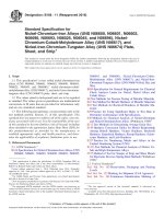
6.4 The wire shall have rounded corners or rounded edges
as specified in Table 3 and as shown in Fig. 1. Where rounded
corners are required, the corners of the wire shall be rounded
within the limits of radii, 25 % under and 25 % over (as
determined by a radius gage) those radii values specified in
Table 3.
7.3 Low Stress Elongation (LSE):
7.3.1 Types A and B wire shall have a minimum LSE value
of 1 % determined in accordance with Test Method B279.
(Explanatory Note 5).
6.5 From each shipping unit, approximately 12 ft (3.66 m)
shall be unwound and the wire gaged at six places between
points 12 in. (30.5 cm) and 12 ft (3.66 m) from the end. The
shipping unit shall be rejected if the average of the measurements obtained is not within the limits specified in 6.2 and 6.3.
7.4 Retests:
7.4.1 If upon testing a sample from any coil or reel of wire,
the results do not conform to the respective requirements of
7.1, 7.2, and 7.3, two additional samples shall be tested, each
of which shall conform to the prescribed requirements.
7. Physical Requirements
7.1 Elongation:
7.1.1 Type A wire shall conform to the requirements for
elongation given in Table 4.
7.1.2 For Type B wire elongation tests shall not be required.
7.1.3 Elongation tests shall be made in accordance with Test
Methods E8/E8M on representative samples. The elongation
shall be determined as the permanent increase in length, due to
the breaking of the wire in tension, measured between gage
marks placed originally 10 in. (250 mm) apart upon the test
specimen (Explanatory Note 2). The fracture shall be in
between gage marks and not closer than 1 in. (25 mm) to either
gage mark.
8. Standard Reference Temperature
8.1 For the purpose of this specification, all wire dimensions
and properties shall be considered as occurring at the internationally standardized reference temperature of 20°C.
9. Standard Rules for Rounding Off
9.1 All calculations for the standard nominal dimensions
and properties of rectangular and square wires shall be rounded
off in the final value only, in accordance with the rounding-off
method of Practice E29.
7.2 Bending:
7.2.1 Both edges of Type B wire shall withstand bending
edgewise through 180° around the mandrel indicated without
cracking. The mandrel shall be one of the sizes shown in Table
5 and shall be the size that is equal to or next larger than the
figure obtained by multiplying the width of the wire by the
factor in Table 6, corresponding to the ratio of the width to the
thickness of the wire. In cases where the mandrel diameter
desired is less than 0.156 in. (3.96 mm) or the thickness is less
10. Nominal Cross-Sectional Areas
10.1 Nominal cross-sectional areas in square mils or square
millimetres shall be calculated by subtracting the area reductions due to rounded corners or rounded edges (see Table 7 and
Table 8) from the product of the specified nominal thickness
and width dimensions in mils (0.001 in.) or millimetres as
applicable. Values so derived shall be rounded off in accordance with Section 9 to the same number of significant figures
TABLE 2 Variation in Width
Specified Width
in.
0.492 and over
Under 0.492 to 0.315, incl
Under 0.315 to 0.098, incl
Under 0.098
mm
Permissible Variation in Width,
max, plus and minus
mm
12.5 and over
under 12.5 to 8.00, incl
under 8.00 to 2.49, incl
under 2.49
1 % but not to exceed 0.016 in. (0.406 mm)
0.003 in. (0.076 mm)
1%
0.001 in. (0.025 mm)
2
B48 − 00 (2016)
TABLE 3 Requirements for Rounded Corners and Rounded Edges
Specified Thickness
Corner Radius for Specified Width
in.
in.
mm
0.689 and over
17.50 and over
under
to, incl
under
to, incl
0.689
0.439
0.280
0.177
0.124
0.098C
0.063D
0.439
0.280
0.177
0.124
0.098
0.063
...
17.50
11.15
7.10
4.50
3.15
2.15C
1.60D
11.15
7.10
4.50
3.15
2.15
1.60
...
mm
in.
mm
in.
mm
0.748
and
over
19.0
and
over
under
0.748 to
0.187,
incl
under
19.0 to
4.75,
incl
under
0.187
under
4.75
0.188
4.78
0.188
4.78
...
...
0.125
3.18
0.094
2.39
0.063
1.60
0.063
1.60
rounded edgeA
rounded edgeA
rounded edgeA
0.094
2.39
0.039
1.00
0.039
1.00
0.03
0.80
B
0.03
0.80B
B
0.03
0.80B
full rounded edgeE
...
...
...
...
0.039
1.00
0.03
0.80
0.026
0.67
0.020
0.50
full rounded edgeE
A
A rounded edge is an edge produced by (1) rolling wire to the size specified either with or without edging rolls or (2) drawing through a die (see Fig. 1).
Rectangular wire with a thickness under 0.124 in. (3.15 mm) to 0.063 in. (1.60 mm) and a width under 0.751 in. (19.08 mm) to 0.189 in. (4.80 mm) may be manufactured
with the corner radius specified for the same thickness and a width under 0.189 in. (4.80 mm).
C
Square wire 0.072 in. (1.83 mm) and under shall have a corner radius of 0.016 in. (0.41 mm) ±25 %.
D
Rectangular wire with a thickness under 0.063 in. (1.60 mm) to 0.03 in. (0.80 mm) may be manufactured with a corner radius of 0.016 in. (0.41 mm) ±25 %.
E
Except as permitted by Footnote B, rectangular wire less than 0.751 in. (19.08 mm) wide with full rounded edge shall have a radius half the thickness of the wire, ±25 %.
B
NOTE 1—The arc is not necessarily tangent to the flats at points A. However, the wire shall be commercially free of sharp, rough, or projecting edges.
FIG. 1 Sections of Wire with Rounded Edges and Rounded Corners
TABLE 4 Requirements for Elongation
Specified Thickness
in.
Elongation in 10
in. (250 mm);
min, %
mm
0.290 and over
Under 0.290 to 0.051, incl
Under 0.051 to 0.021, incl
Under 0.021 to 0.011, incl
Under 0.011
7.37 and over
under 7.37 to 1.30, incl
under 1.30 to 0.53, incl
under 0.53 to 0.28, incl
under 0.28
TABLE 5 Standard Mandrel Sizes for Edgewise Bend Test
TABLE 6 Factor for Determining Mandrel Size for Edgewise Bend
Test
Mandrel Diameters
in.
mm
in.
mm
0.156
0.188
0.220
0.250
0.312
0.375
0.438
0.500
3.96
4.78
5.59
6.35
7.98
9.52
11.1
12.7
0.625
0.750
0.875
1.000
1.250
1.500
1.750
2.000A
15.9
19.0
22.2
25.4
31.8
38.1
44.4
50.8
35
32
32
25
20
Multiplying Factor
to Determine
Mandrel Size
Width to Thickness Ratio
30 to 20, incl
Under 20 to 10, incl
Under 10 to 5, incl
Under 5 to 2.5, incl
Under 2.5
A
The maximum mandrel diameter of 2 in. (50.8 mm) is based on the suggested
maximum width of strap, made from round copper wire, of 1.250 in. (31.8 mm),
established by the Copper Development Association.
1.50
1.25
1.00
0.75
0.50
following equations and shall be rounded off in the final value
only, in accordance with Section 9, to the same number of
significant figures as used in expressing the nominal
dimensions, but in no case to less than three significant figures:
as used in expressing the nominal dimensions, but in no case to
less than three significant figures.
Mass/Unit Length, lb/1000 ft 5 3.8540 3 A 3 1023
11. Nominal Mass/Unit Length and Length
11.1 Nominal mass/unit length and lengths shall be calculated from the nominal wire dimensions in accordance with the
kg/km 5 8.89 3 A 1
Length, ft/lb 5 ~ 2.5947 3 10 5 ! /A
3
B48 − 00 (2016)
TABLE 7 Areas of Square Copper Wire
Nominal Size
in.
A
mm
Calculated Area of
Perfect
Square
mil2
3
Nominal Corner
Radius
mm2
in.
4
Calculated DepartureA
mils2
mm
mm2
Nominal Area
mils 2
9
Nominal Area Working Value
mm2
10
mils2
mm2
11
12
1
2
5
6
7
8
0.0508
0.0571
0.0641
0.0720
1.290
1.450
1.628
1.829
2580.64
3260.41
4108.81
5184.00
1.66493
2.10349
2.65038
3.34451
0.016
0.016
0.016
0.016
0.41
0.41
0.41
0.41
219.75
219.75
219.75
219.75
0.14177
0.14177
0.14177
0.14177
2360.89
3040.66
3889.06
4964.25
1.52315
1.96171
2.50907
3.20274
2.36 × 10 3
3.04
3.89
4.96
1.52
1.96
2.51
3.20
0.0808
0.0907
0.1019
0.1144
2.052
2.304
2.588
2.906
6528.64
8226.49
10383.61
13087.36
4.21202
5.30740
6.69909
8.44344
0.020
0.020
0.026
0.026
0.51
0.51
0.66
0.66
343.36
343.36
580.28
580.28
0.22151
0.22151
0.37437
0.37437
6185.28
7883.13
9803.33
12507.08
3.99050
5.08588
6.32472
8.06907
6.19
7.88
9.80
12.51
3.99
5.09
6.32
8.07
0.1285
0.1443
0.1620
0.1819
3.264
3.665
4.115
4.620
16512.25
20822.49
26244.00
33087.61
10.65304
13.43384
16.93158
21.34680
0.032
0.032
0.032
0.040
0.81
0.81
0.81
1.02
879.00
879.00
879.00
1373.44
0.56710
0.56710
0.56710
0.88609
15633.25
19943.49
25365.00
31714.17
10.08595
12.86674
16.36448
20.46071
15.63
19.94
25.36†
31.71
10.09
12.87
16.36
20.46
0.2043
0.2294
0.2576
0.2893
5.189
5.827
6.543
7.348
41738.49
52624.36
66357.76
83694.49
26.92800
33.95113
42.81137
53.99634
0.040
0.040
0.040
0.040
1.02
1.02
1.02
1.02
1373.44
1373.44
1373.44
1373.44
0.88609
0.88609
0.88609
0.88609
40365.05
51250.92
64984.32
82321.05
26.04192
33.06504
41.92528
53.11025
40.37
51.25
64.98
82.32
26.04
33.07
41.93
53.11
0.3249
0.3648
0.4096
0.4600
8.252
9.266
10.404
11.684
105560.01 68.10310
133097.04 85.86889
167772.16 108.23989
211600.00 136.51586
0.040
0.040
0.040
0.094
1.02
1.02
1.02
2.39
1373.44
1373.44
1373.44
7584.82
0.88609
0.88609
0.88609
4.89342
104186.57
131723.60
166398.72
204015.18
67.21701
84.98280
107.35380
131.62243
104.2
131.7
166.4
204.0
67.22
84.98
107.4
131.6
The reduction in area due to rounding the corners.
TABLE 8 Calculated Reduction in Area Due to Rounding of Corners of Rectangular Wire
Specified Thickness
in.
mm
0.689 and over
under
to, incl
0.689
0.439
0.439
0.226
0.226
0.166
0.166
0.126
0.126
0.096
0.096
0.061
0.061
...
17.50 and over
under
to, incl
17.50
11.15
11.15
5.74
5.24
4.22
4.22
3.20
3.20
2.44
2.44
1.55
1.55
...
Specified Width
in.
mm
under
under
0.751 to
19.08 to
0.189, incl
4.80, incl
Calculated Reduction
mils2
mm2
in.
mm
0.751
and over
19.08
and over
mils2
mm2
30339.29
19.5732
30339.29
13412.50
7584.82
3406.90
3406.00
8.65321
4.89342
2.19805
2.19805
A
A
A
A
7584.82
1373.44
1373.44
879.00
879.00
879.00
A
A
A
in.
mm
under
0.189
under
4.80
mils2
mm2
19.5737
...
...
4.89342
0.88609
0.88609
0.56710
0.56710
0.56710
...
...
1373.44
879.00
580.28
343.36
...
...
0.88609
0.56710
0.37437
0.22152
A
A
A
A
For wire with rounded edges, the calculated reduction in area in square mils is equivalent to 214600 T2, where T is the thickness of the wire in inches, and the calculated
reduction in area in square mm is equivalent to 0.2146T12, where T1 is the thickness of the wire in millimetres. For square wire, see Table 7.
12.2 Tests to determine conformance to electrical resistance
requirements shall be made on the uninsulated conductor in
accordance with Test Method B193.
m/kg 5 112.486/A 1
where:
A = nominal cross-sectional area in square mils, obtained in
accordance with Section 10, and
A1 = nominal cross-sectional area in square millimetres
obtained in accordance with Section 10.
12.3 Nominal resistances and other values derived from the
resistivity units shall be calculated from the nominal wire
dimensions in accordance with the following equations and all
values so derived shall be rounded off in the final value only,
in accordance with Section 9, to the same number of significant
figures as used in expressing the nominal dimensions, but in no
case to less than three significant figures:
12. Resistivity
12.1 Electrical resistivity shall be determined on representative samples by resistance measurements (Explanatory Note
9). At a temperature of 20°C, the resistivity shall not exceed
0.017241Ω · mm2/m.
dc resistance at 20°C, Ω/1000 ft 5 ~ 8.1458 3 10 3 ! /A
dc resistance at 20°C, Ω/km 5 17.241/A 1
4
B48 − 00 (2016)
16. Packaging and Shipping
dc resistance at 20°C, Ω/lb 5 ~ 2.1135 3 10 6 ! /A 2
dc resistance at 20°C, Ω/kg 5 1.9394/A
2
16.1 Package sizes shall be agreed upon by the manufacturer and the purchaser in the placing of individual orders
(Explanatory Note 11).
1
Length at 20°C ft/Ω 5 0.12277 3 A
Length at 20°C, m/Ω 5 58,000 3 A 1
16.2 The wire shall be protected against damage in ordinary
handling and shipping.
Mass at 20°C, lb/Ω 5 0.47315 3 A 2 3 1026
Mass at 20°C, g/Ω 5 515.62 3 A 1 2
16.3 Unless otherwise agreed upon, the wire shall be
shipped in continuous lengths of not less than the weights
shown in Table 9.
where:
A = the nominal cross-sectional area of the wire in square
mils, obtained in accordance with Section 10,
A1 = the nominal cross-sectional area of the wire in square
mm, obtained in accordance with Section 10.
17. Precision and Bias
13. Density
17.1 Precision—This specification has been in use for many
years. No statement of precision has been made and no work
has been planned to develop such a statement.
13.1 For the purpose of calculating mass, cross sections, and
so forth, the density of the copper shall be taken as 8.89
g/cm3 (0.32117 lb/in.3) at 20°C (Explanatory Note 10).
17.2 Bias—This specification has no bias because the value
for cross-sectional area is determined solely in terms of this
specification.
14. Finish
18. Keywords
14.1 The wire shall be free of all imperfections not consistent with good commercial practice.
18.1 copper bare electrical conductor; copper wire; soft
square and rectangular copper wire
15. Inspection
TABLE 9 Minimum Mass
15.1 All tests and inspection shall be made at the place of
manufacture unless otherwise especially agreed upon between
the manufacturer and purchaser at the time of purchase. The
manufacturer shall afford the inspector representing the purchaser all reasonable facilities to satisfy him that the material
is being furnished in accordance with this specification.
Nominal Area
mil2
5001 and over
Under 5001 to 2000,
incl
Under 2000
mm2
3.23 and over
under 3.23 to 1.29, incl
under 1.29
Minimum Mass
lb
kg
135
61.2
65
29.5
30
13.6
EXPLANATORY NOTES
necessary with spectacles, the sample is considered to have failed the
edgewise bend test.
NOTE 5—LSE test results are affected by small amounts of cold
working. The specified 1 % minimum LSE value applies only to bare wire
before further processing.
NOTE 6—It is urged that gage numbers be avoided entirely in connection with rectangular wire. Not only are there several systems of gage
numbers, but confusion is likely to result even if the identity of the
particular gage is known since it may not be clear whether the gage
number refers to the thickness dimension or to the area of a round wire
having a diameter equal to that gage number. Definite dimensions of
thickness and width in decimal fractions of an inch or in millimetres are
much preferred.
Square wire sizes sometimes are expressed in terms of AWG sizes, as
“No. 8 AWG Square.” This terminology is confusing and its use is not
recommended. However, when a square wire size is expressed in this
manner, it refers to a square circumscribing a circle whose diameter is that
of a round wire of the specified AWG size.
NOTE 7—Table 7 gives data on the cross sectional area of square wire
in sizes 0.0508 in. (1.29 mm) to 0.4600 in. (11.68 mm), incl, allowance
having been made for reduction of the theoretical area of a perfect square
wire due to the rounding of its four corners as shown in Table 3 of this
specification. These areas are for the nominal dimensions shown in
Columns 1 and 2 of Table 7 and do not take into account the variation in
the dimensions permitted by the tolerances given in the specification. The
significance of these nominal working area values should not extend
beyond the significance of the values in Columns 1 and 2 and it is for this
reason that the nominal working area values have been rounded off as
shown in Columns 11 and 12. Attention is also called to the fact that the
values obtained by the equations of 12.3 are for wire of nominal
NOTE 1—Soft or annealed copper wire is wire that has been drawn or
rolled to size by customary operations and then annealed. When necessary,
it is finished by cleaning to remove scale or oxide. It is not limited in size
by the Copper Development Association definition of flat wire, namely
0.188 in. (4.77 mm) maximum thickness by 11⁄4 in. (31.8 mm) maximum
width. The wire is soft and ductile, easily marred, and even stretched by
careless handling. It is therefore necessary that the requirements of this
specification relating to elongation properties and resistivity refer to the
wire as it is put up by the manufacturer, and before being put through
processes incident to its use by the purchaser.
NOTE 2—In general, tested values of elongation are reduced with
increase in speed of the moving head of the testing machine in the tension
testing of copper wire. In the case of tests on soft or annealed copper wire,
however, the effects of speed of testing are not pronounced. Tests of soft
wire made at speeds of moving head, which under no-load conditions are
not greater than 12 in. (300 mm)/min, do not alter the final results of
elongation determinations to any practical extent.
NOTE 3—Edgewise bend characteristics are affected by small amounts
of cold working and by imperfections in the surface or edges of the wire.
Care must be taken in selecting the sample to be sure that the wire has not
been damaged where the edgewise bend test is to be applied. The
edgewise bend test equipment should make provision to hold the sample
flat while the bend is being made. When samples under 0.050 in. (1.27
mm) are being tested, it is recommended that a number of samples be bent
at the same time to give an effective thickness of not less than 0.060 in.
(1.52 mm).
NOTE 4—In considering the results of the edgewise bend test, slight
surface roughness or the so-called “Orange Peel Effect” is not considered
cause for rejection. If minute fissures are visible, either on the edge or the
corners, when the sample is viewed with normal near vision corrected if
5
B48 − 00 (2016)
annealed copper equal to 100 % conductivity. This term means that a wire
1 m in length and weighing 1 g would have a resistance of 0.15328 Ω. This
is equivalent to a resistivity value of 875.20 Ω·lb/mile2, which signifies the
resistance of a wire 1 mile in length weighing 1 lb. It is also equivalent,
for example, to 1.7241 µΩ/cm of length of a bar 1 cm2 in cross section. A
complete discussion of this subject is contained in NBS Handbook 100 of
the National Institute of Standards and Technology. Relationships which
may be useful in connection with the values of resistivity prescribed in this
specification are as follows:
dimensions and do not take into account probable increase or decrease of
the values due to the variations of the dimensions of an actual wire within
the limits of the specified tolerances. Square mils and square millimetres
are terms used to express cross-sectional area of square and rectangular
sections. A square mil is the area of a square, 1 mil on each side. A square
millimetre is the area of a square, 1 mm on each side. Thus, if dimensions
of a rectangular section are expressed in mils or millimetres, the area of
that section in square mils or square millimetres, respectively, is the
product of thickness times width. The relationship between circular mils
and square mils is that of a circle to its circumscribing square. Thus, 1
cmil = 0.7854 mil2.
NOTE 8—Table 8 gives the calculated area in square mils or square
millimetres to be deducted, because of the rounding of the four corners of
the rectangular wire from the area of a circumscribing rectangle having the
same thickness and width, in order to obtain the working net area of the
wire. The areas to be deducted are based on the radii specified in Table 3
of this specification, and do not take into account probable increase or
decrease of the area of an actual wire due to the variation in its dimensions
within the limits of the tolerances given in this specification. As in the case
of square wire, working net areas of rectangular wire should not extend to
a number of significant figures greater than that employed in specifying its
thickness and width. This is also true of any other derived values such as
circular-mil area, weight or electrical resistance.
NOTE 9—“Resistivity” is used in place of “percentage conductivity”
and the resistivity units are based on the International Annealed Copper
Standard adopted by IEC in 1913, which is 1⁄58 Ω·mm2/m. The value of
0.017241 Ω·mm2/m and the value of 0.15328 Ω·g/m at 20°C are
respectively the international standard of volume and mass resistivity of
Conductivity at 20°C, %
Ω·lb/mile2
Ω·g/m2
Ω·cmil/ft
Ω·mm2/m
µΩ·in.
µΩ·cm
100.00
875.20
0.15328
10.371
0.017241
0.67879
1.7241
The use of five significant figures in expressing resistivity does not
imply the need for greater accuracy of measurement than that specified in
Test Method B193. The use of five significant figures is required for
complete reversible conversion from one set of resistivity units to another.
NOTE 10—The value of density of copper is in accordance with the
International Annealed Copper Standard. The corresponding value at 0°C
is 8.90 g/cm3 (0.32150 lb/in.3). The subject of density is discussed at
length in NBS Handbook 100.
NOTE 11—Attention is called to the desirability for agreement between
the manufacturer and purchaser on package sizes, which will be sufficiently large and yet not so heavy or bulky that the wire may likely be
damaged in handling.
ASTM International takes no position respecting the validity of any patent rights asserted in connection with any item mentioned
in this standard. Users of this standard are expressly advised that determination of the validity of any such patent rights, and the risk
of infringement of such rights, are entirely their own responsibility.
This standard is subject to revision at any time by the responsible technical committee and must be reviewed every five years and
if not revised, either reapproved or withdrawn. Your comments are invited either for revision of this standard or for additional standards
and should be addressed to ASTM International Headquarters. Your comments will receive careful consideration at a meeting of the
responsible technical committee, which you may attend. If you feel that your comments have not received a fair hearing you should
make your views known to the ASTM Committee on Standards, at the address shown below.
This standard is copyrighted by ASTM International, 100 Barr Harbor Drive, PO Box C700, West Conshohocken, PA 19428-2959,
United States. Individual reprints (single or multiple copies) of this standard may be obtained by contacting ASTM at the above
address or at 610-832-9585 (phone), 610-832-9555 (fax), or (e-mail); or through the ASTM website
(www.astm.org). Permission rights to photocopy the standard may also be secured from the Copyright Clearance Center, 222
Rosewood Drive, Danvers, MA 01923, Tel: (978) 646-2600; />
6