Astm b 63 07 (2013)
Bạn đang xem bản rút gọn của tài liệu. Xem và tải ngay bản đầy đủ của tài liệu tại đây (140.89 KB, 4 trang )
Designation: B63 − 07 (Reapproved 2013)
Standard Test Method for
Resistivity of Metallically Conducting Resistance and
Contact Materials1
This standard is issued under the fixed designation B63; the number immediately following the designation indicates the year of original
adoption or, in the case of revision, the year of last revision. A number in parentheses indicates the year of last reapproval. A superscript
epsilon (´) indicates an editorial change since the last revision or reapproval.
This standard has been approved for use by agencies of the U.S. Department of Defense.
1. Scope
ρ 5 RA/L
1.1 This test method covers the determination, to a precision
of 2 %, of the electrical resistivity of materials used in
resistors, heating elements, and electrical contacts, as well as
products of powder metallurgy processes which are used for
other purposes.
(1)
where R is the resistance in ohms of a specimen of the
material of uniform cross section A and of a length L. In
reporting values of resistivity under this test A shall be expressed in square centimeters and L in centimeters. Resistivity is measured in micro ohm-meter. English units of ohms
circular mil per foot are expressed as:
NOTE 1—For determining the resistivity of electrical conductors, see
Test Method B193.
ρ 5 12 3 106 R A/0.7854 L
1.2 The values stated in inch-pound units are to be regarded
as standard. The values given in parentheses are mathematical
conversions to SI units that are provided for information only
and are not considered standard.
1.3 This standard does not purport to address all of the
safety concerns, if any, associated with its use. It is the
responsibility of the user of this standard to become familiar
with all hazards including those identified in the appropriate
Material Safety Data Sheet (MSDS) for this product/material
as provided by the manufacturer, to establish appropriate
safety and health practices, and determine the applicability of
regulatory limitations prior to use.
(2)
where:
R = resistance in ohms
A = uniform cross section area in square inches
L = length in inches
4. Significance and Use
4.1 In the case of materials for resistors and heating
elements, a knowledge of resistivity is important in determining whether wire or strip of a specified area of cross section and
length will have a required resistance. It serves as one basis for
the selection of materials for specific applications and its
measurement is a necessary acceptance test for resistance
materials.
2. Referenced Documents
4.2 In the case of materials for electrical contacts, the
measurement of resistivity can serve as a test for uniformity of
materials of nominally the same composition and structure.
2.1 ASTM Standards:2
B193 Test Method for Resistivity of Electrical Conductor
Materials
3. Terminology
5. Apparatus
3.1 Definitions:
3.1.1 resistivity, n—that property of a material which determines its resistance to the flow of an electric current, expressed
as:
5.1 Means for applying current and voltage terminals to the
specimen are specified in Section 9. An optional suitable
specimen holder for nonductile materials is shown in Fig. 1.
5.2 A suitable bridge, potentiometer, digital ohmmeter, or
equivalent, with necessary accessories for making resistance
measurements with a limit of error of less than 0.5 %.
1
This test method is under the jurisdiction of ASTM Committee B02 on
Nonferrous Metals and Alloys and is the direct responsibility of Subcommittee
B02.10 on Thermostat Metals and Electrical Resistance Heating Materials.
Current edition approved May 1, 2013. Published May 2013. Originally
approved in 1926. Last previous edition approved in 2007 as B63 – 07. DOI:
10.1520/B0063-07R13.
2
For referenced ASTM standards, visit the ASTM website, www.astm.org, or
contact ASTM Customer Service at For Annual Book of ASTM
Standards volume information, refer to the standard’s Document Summary page on
the ASTM website.
5.3 Means for measuring the dimensions of the specimen,
adequate to determine its length and its mean area of cross
section, each within 0.5 %.
6. Test Specimen
6.1 Ductile Materials—The test specimen for ductile
materials, including those used for contacts, shall be in the
Copyright © ASTM International, 100 Barr Harbor Drive, PO Box C700, West Conshohocken, PA 19428-2959. United States
1
B63 − 07 (2013)
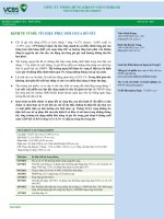
Item
1
2
3
4
5
6
7
8
9
Description
Dimensions, in. (mm)
Base block
Clamp block
Current lead clamp screw, knurled head
Specimen clamp screw, knurled head
Pivot bracket
Pivot
Pivot block
Potential knife-edge
Specimen being tested
⁄ by 3 by 4 (12.7 by 76.2 by 101.6)
⁄ by 1 by 1 (19.0 by 25.4 by 25.4)
10⁄32 by 3⁄16
1⁄4 in. by 40 by 1 in.
1⁄2 by 15⁄16 by 17⁄16 (12.7 by 23.8 by 36.5)
...
1⁄2 by 23⁄32 by 3 (12.7 by 53.2 by 76.2)
...
...
12
34
Material
Number
Required
micarta
copper
brass
brass
steel
steel
micarta
steel
...
1
2
2
2
2
2
1
2 sets
...
NOTE 1—Contact surfaces must be clean and free of visible oxide.
FIG. 1 Specimen Holder for Nonductile Materials
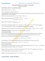
material is readily machinable. For materials which are not
readily machinable, such as those containing graphite, a flat
strip may be used as a test specimen. In order to determine the
resistivity with a precision of 2 %, each specimen shall
conform to the following:
6.2.1 The diameter of a specimen (Fig. 2), or the thickness
and width of a strip specimen, shall be uniform within 1 %.
6.2.2 It shall show no surface cracks or other defects
observable with normal vision, and shall be free from surface
oxide.
form of a wire or a strip. In order to determine the resistivity
with a precision of 2 %, it is necessary that the resistance,
cross-sectional area, and length shall be measured with a limit
of error within 0.5 %. To ensure this limit of error each test
specimen shall conform to the following:
6.1.1 It shall have a length of at least 0.5 ft (15 cm) between
potential probes.
6.1.2 It shall have a resistance of at least 0.001 Ω.
6.1.3 If the cross section is to be determined by direct
measurement, the diameter of a wire specimen or the thickness
of a strip specimen shall not be less than the limits defined by
the 0.5 % criteria of 6.1, and this dimension throughout the
length of the specimen shall not vary by more than 3 %.
6.1.4 It shall show no surface cracks or other defects
observable with normal vision, and shall be free from surface
oxide.
7. Length Measurements
7.1 The length may be measured by any scale which will
give an accuracy of 0.5 % in the length measured. In case
potential leads are used, the length shall be taken between the
potential contacts. In the direction of the length of specimen,
the dimension of each potential contact, including soldering
surface or clamp contact area, shall not be more than 0.5 % of
6.2 Nonductile Materials—The test specimen for nonductile
materials shall be made in accordance with Fig. 2 if the
2
B63 − 07 (2013)
E = weight of specimen in water, g
The cross-sectional area, A, in square centimeters, may be
found from the equation:
A 5 ~ B 2 E ! /L
8.3.2 For porous materials such as products of powder
metallurgy, weigh a specimen of at least 10 g in air. Immerse
the specimen for at least 4 h in oil (viscosity of approximately
200 SUS at 37.8°C (100°F), held at a temperature of 82.2 6
5.5°C (180 6 10°F). Then cool the specimen to room temperature by immersing it in oil at room temperature. After
removing excess oil from the specimen by means of a soft
cloth, weigh the specimen in air and then in water. Calculate
the density from the equation:
NOTE 1—Metric equivalents are as follows.
in.
mm
in.
mm
0.010
0.012
0.187
0.188
0.237
0.25
0.30
4.75
4.78
6.01
0.438
2.000
2.375
3.250
11.12
50.80
60.32
82.55
D 5 B/ ~ C 2 E !
(5)
where:
D = density, g/cm3
B = weight of the unimpregnated specimen in air, g
C = weight of the specimen impregnated with oil (in air), g
E = weight of the impregnated specimen in water, g
The cross-sectional area, A, in square centimetres, may be
found from the equation:
FIG. 2 Resistivity Test Specimen for Machinable Nonductile Materials
the distance between the potential contacts. In the case of the
specimen holder for nonductile materials shown in Fig. 1, the
distance between the potential contacts may be found by
measuring from the outside flat of one potential knife edge to
the outside flat of the other. A micrometer or other suitable
means shall be used for measuring this length.
A 5 ~ C 2 E ! /L
(6)
9. Leads
9.1 Specimens with a resistance of less than 10 Ω shall be
provided with both current and potential leads. The minimum
distance between each potential contact and the adjacent
current lead shall be at least three times the diameter of the
wire or the width of the strip. Current shall be introduced into
the specimen with current leads amply large to minimize
heating of the specimen. Specimens with a resistance greater
than 10 Ω do not require potential leads, though they may be
used, if desired.
8. Cross-Sectional Area Measurements
8.1 In general, the diameter of a specimen of circular cross
section, or the thickness and width of a strip specimen, shall be
determined by micrometer measurements, and a sufficient
number of measurements shall be made to obtain the mean
cross section to within 0.5 %.
8.2 In case the diameter of the cylinder or the thickness of
the strip cannot be measured to give the above accuracy with
the micrometer available, determine the cross section from the
weight, density, and length of specimen.
10. Resistance Measurements
10.1 Resistance of specimens provided with potential leads
shall be measured with a Kelvin bridge, potentiometer, digital
ohmmeter, or equivalent capable of measuring the resistance
between the potential contacts with a limit of error within
0.5 %. Specimens with a resistance of more than 1 Ω may be
measured with a limit of error within 0.5 % by means of a
suitable Wheatstone bridge.
8.3 When the density is unknown, it may be determined as
follows:
8.3.1 For nonporous materials first weigh a sample of at
least 10 g in air and then in water. The density in grams per
cubic centimetre is equivalent to the weight in air divided by
the loss of weight due to submergence in water. The water shall
be at room temperature to avoid errors due to convection
currents. For the accuracy required, no corrections are necessary for the temperature of the water or for the buoyancy of the
air. However, exercise care to remove all air bubbles from the
specimen when weighing it in water. To remove air bubbles
from a specimen of fine wire, dip the wire, in the form of a
loosely wound coil, in alcohol and rinse in water before
immersing it in the water to be used in weighing. Then
calculate the density from the following equation:
D 5 B/ ~ B 2 E !
(4)
11. Heating of Specimen
11.1 In all resistance measurements, the measuring current
raises the temperature of the specimen above that of the
surrounding medium. If this is sufficient to change the resistance by 0.5 %, a correction shall be made. In general, the
smallest current that will give the sensitivity necessary to
measure to 0.5 % of the resistance shall be used. A convenient
test to determine whether a correction should be applied is to
increase the current to 1.4 times the value it had when the
measurement was made (Note 2) and then to measure the
resulting change in resistance. If this change is as large as
0.5 % of the measured value, a correction should be made. For
a material which has a positive temperature coefficient of
(3)
where:
D = density, g/cm3
B = weight of specimen in air, g
3
B63 − 07 (2013)
11.2 Measurements are to be in a controlled temperature
environment.
12.1.5.1 If by micrometer, a record of all micrometer
readings, including average values and calculated crosssectional area,
12.1.5.2 If by weighing, a record of length, mass and density
determinations and calculated cross-sectional area,
12.1.6 Method of measuring resistance,
12.1.7 Value of resistance,
12.1.8 Calculated value of electrical resistivity, and
12.1.9 Previous mechanical and thermal treatments. (Since
the resistivity of a material usually depends upon them, these
shall be stated whenever the information is available.)
12. Report
13. Precision and Bias
resistance, the resistance at the temperature of the surrounding
medium shall be obtained by subtracting the measured change
from the resistance as measured with the smaller current. For
material with a negative temperature coefficient, this difference
shall be added to the resistance obtained by measurements with
the smaller current.
NOTE 2—Increasing the current to 1.4 times the value it had when the
measurement was made serves to very nearly double the heating effect,
and, for small changes in temperature, the rise in temperature.
13.1 The precision of this test method is within 2 %.
12.1 Report the following information:
12.1.1 Identification of test specimen,
12.1.2 Material type,
12.1.3 Temperature of surrounding medium,
12.1.4 Length of specimen used,
12.1.5 Method of obtaining cross-sectional area:
13.2 The bias of this test method is less than 1 %.
14. Keywords
14.1 contact materials; electrical conductors; heating elements; resistivity; resistors; specific resistance
ASTM International takes no position respecting the validity of any patent rights asserted in connection with any item mentioned
in this standard. Users of this standard are expressly advised that determination of the validity of any such patent rights, and the risk
of infringement of such rights, are entirely their own responsibility.
This standard is subject to revision at any time by the responsible technical committee and must be reviewed every five years and
if not revised, either reapproved or withdrawn. Your comments are invited either for revision of this standard or for additional standards
and should be addressed to ASTM International Headquarters. Your comments will receive careful consideration at a meeting of the
responsible technical committee, which you may attend. If you feel that your comments have not received a fair hearing you should
make your views known to the ASTM Committee on Standards, at the address shown below.
This standard is copyrighted by ASTM International, 100 Barr Harbor Drive, PO Box C700, West Conshohocken, PA 19428-2959,
United States. Individual reprints (single or multiple copies) of this standard may be obtained by contacting ASTM at the above
address or at 610-832-9585 (phone), 610-832-9555 (fax), or (e-mail); or through the ASTM website
(www.astm.org). Permission rights to photocopy the standard may also be secured from the Copyright Clearance Center, 222
Rosewood Drive, Danvers, MA 01923, Tel: (978) 646-2600; />
4