Astm b 924 02 (2017)
Bạn đang xem bản rút gọn của tài liệu. Xem và tải ngay bản đầy đủ của tài liệu tại đây (130.56 KB, 5 trang )
This international standard was developed in accordance with internationally recognized principles on standardization established in the Decision on Principles for the
Development of International Standards, Guides and Recommendations issued by the World Trade Organization Technical Barriers to Trade (TBT) Committee.
Designation: B924 − 02 (Reapproved 2017)
Standard Specification for
Seamless and Welded Nickel Alloy Condenser and Heat
Exchanger Tubes With Integral Fins1
This standard is issued under the fixed designation B924; the number immediately following the designation indicates the year of
original adoption or, in the case of revision, the year of last revision. A number in parentheses indicates the year of last reapproval. A
superscript epsilon (´) indicates an editorial change since the last revision or reapproval.
1. Scope
A941 Terminology Relating to Steel, Stainless Steel, Related
Alloys, and Ferroalloys
B163 Specification for Seamless Nickel and Nickel Alloy
Condenser and Heat-Exchanger Tubes
B167 Specification for Nickel-Chromium-Iron Alloys (UNS
N06600, N06601, N06603, N06690, N06693, N06025,
N06045, and N06696), Nickel-Chromium-CobaltMolybdenum Alloy (UNS N06617), and Nickel-IronChromium-Tungsten Alloy (UNS N06674) Seamless Pipe
and Tube
B407 Specification for Nickel-Iron-Chromium Alloy Seamless Pipe and Tube
B423 Specification
for
Nickel-Iron-ChromiumMolybdenum-Copper Alloy (UNS N08825, N08221, and
N06845) Seamless Pipe and Tube
B444 Specification for Nickel-Chromium-MolybdenumColumbium Alloys (UNS N06625 and UNS N06852) and
Nickel-Chromium-Molybdenum-Silicon Alloy (UNS
N06219) Pipe and Tube
B468 Specification for Welded UNS N08020 Alloy Tubes
B515 Specification for Welded UNS N08120, UNS N08800,
UNS N08810, and UNS N08811 Alloy Tubes
B516 Specification for Welded Nickel-Chromium-Iron Alloy
(UNS N06600, UNS N06601, UNS N06603, UNS
N06025, UNS N06045, UNS N06690, and UNS N06693)
Tubes
B622 Specification for Seamless Nickel and Nickel-Cobalt
Alloy Pipe and Tube
B626 Specification for Welded Nickel and Nickel-Cobalt
Alloy Tube
B674 Specification for UNS N08925, UNS N08354, and
UNS N08926 Welded Tube
B676 Specification for UNS N08367 Welded Tube
B677 Specification for UNS N08925, UNS N08354, and
UNS N08926 Seamless Pipe and Tube
B690 Specification
for
Iron-Nickel-ChromiumMolybdenum Alloys (UNS N08366 and UNS N08367)
Seamless Pipe and Tube
B704 Specification for Welded UNS N06625, UNS N06219
and UNS N08825 Alloy Tubes
B729 Specification for Seamless UNS N08020, UNS
N08026, and UNS N08024 Nickel-Alloy Pipe and Tube
2
1.1 This specification describes seamless and welded
nickel alloy tubing on which the external or internal surface, or
both, has been modified by a cold forming process to produce
an integral enhanced surface, for improved heat transfer. The
tubes are used in surface condensers, evaporators, heat exchangers and similar heat transfer apparatus in unfinned end
diameters up to and including 1 in. (25.4 mm).
1.2 The values stated in inch-pound units are to be regarded
as standard. The values given in parentheses are mathematical
conversions to SI units that are provided for information only
and are not considered standard.
1.3 The following precautionary statement pertains to the
test method portion only: Section 10 of this specification. This
standard does not purport to address all of the safety concerns,
if any, associated with its use. It is the responsibility of the user
of this standard to become familiar with all hazards including
those identified in the appropriate Safety Data Sheet (SDS) for
this product/material as provided by the manufacturer, to
establish appropriate safety and health practices, and determine the applicability of regulatory requirements prior to use.
1.4 This international standard was developed in accordance with internationally recognized principles on standardization established in the Decision on Principles for the
Development of International Standards, Guides and Recommendations issued by the World Trade Organization Technical
Barriers to Trade (TBT) Committee.
2. Referenced Documents
2.1 ASTM Standards:3
1
This specification is under the jurisdiction of ASTM Committee B02 on
Nonferrous Metals and Alloys and is the direct responsibility of Subcommittee
B02.07 on Refined Nickel and Cobalt and Their Alloys.
Current edition approved April 1, 2017. Published April 2017. Originally
approved in 2002. Last previous edition approved in 2012 as B924 – 02 (2012).
DOI: 10.1520/B0924-02R17.
2
For ASME Boiler and Pressure Vessel Code applications, see related Specification SB-924 in Section II of that Code.
3
For referenced ASTM standards, visit the ASTM website, www.astm.org, or
contact ASTM Customer Service at For Annual Book of ASTM
Standards volume information, refer to the standard’s Document Summary page on
the ASTM website.
Copyright © ASTM International, 100 Barr Harbor Drive, PO Box C700, West Conshohocken, PA 19428-2959. United States
1
B924 − 02 (2017)
B751 Specification for General Requirements for Nickel and
Nickel Alloy Welded Tube
B829 Specification for General Requirements for Nickel and
Nickel Alloys Seamless Pipe and Tube
B899 Terminology Relating to Non-ferrous Metals and Alloys
E426 Practice for Electromagnetic (Eddy Current) Examination of Seamless and Welded Tubular Products, Titanium,
Austenitic Stainless Steel and Similar Alloys
E571 Practice for Electromagnetic (Eddy-Current) Examination of Nickel and Nickel Alloy Tubular Products
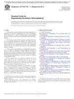
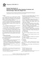
FIG. 1 Outside Enhancement Only
3. Terminology
3.1 For definition of general terms used in this specification,
refer to Terminologies A941 and B899.
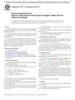
3.2 Definitions of Terms Specific to this Document (Integral
Fin Tube Nomenclature):
D = outside diameter of unenhanced section
Di = inside diameter of unenhanced section
dr = root diameter of enhanced section outside of tube
do = outside diameter of enhanced section
di = inside diameter of enhanced section
W = wall thickness of unenhanced section
Wf = wall thickness of enhanced section
Fh = height of fin—enhanced section outside of tube
Fm = mean fin thickness—enhanced section outside of
tube
P = mean rib pitch—enhanced section inside of tube
Rh = height of rib—enhanced section inside of tube
Ha = rib helix angle—enhanced section inside of tube
Tt = transition taper
FIG. 2 Outside and Inside Enhancement
5. General Requirements
5.1 Seamless material furnished under this specification
shall conform to the requirements of Specification B829,
unless otherwise provided herein.
5.2 Welded material furnished under this specification shall
conform to the applicable requirements of Specification B751,
unless otherwise provided herein.
5.3 Enhanced (integrally finned) sections of the tube shall
be produced by cold forming the tubing in such a manner that
exterior fins, wall under the fin and inside ribs (when specified)
are homogeneous.
4. Ordering Information
4.1 It is the responsibility of the purchaser to specify all
requirements that are necessary for material ordered under this
specification. Such requirements may include, but are not
limited to, the following:
4.1.1 ASTM designation and year of issue (this
specification),
4.1.2 ASTM designation and year of issue (plain tube
specification),
4.1.3 Welded or seamless,
4.1.4 Alloy grade and UNS designation,
4.1.5 Dimensions; plain tube outside diameter, plain tube
wall thickness (ave. or min. specified), length and location of
unenhanced surfaces and the total tube length. Configuration of
enhanced surfaces (fins per unit length, fin height, wall
thickness under fin, rib pitch, rib height, etc.) shall be as agreed
upon between the manufacturer and purchaser. (Refer to Figs.
1 and 2).
4.1.6 Temper (as-finned or stress relief annealed),
4.1.7 Quantity,
4.1.8 Packaging,
4.1.9 Nondestructive tests,
4.1.10 Customer inspection,
4.1.11 Mill test report, and
4.1.12 Certification.
5.4 Tubes described by this specification shall be furnished
with unenhanced (plain) ends.
5.5 Enhanced sections of the tube are normally supplied in
the “as finned” temper (cold worked condition produced by the
enhancing operation). The unenhanced sections of the tube
shall be in the annealed condition and shall be suitable for
rolling-in operations.
6. Materials and Manufacture
6.1 The integrally enhanced (finned) tubes shall be manufactured from seamless, welded, or welded/cold worked plain
tubes that conform to one of the following ASTM specifications: B163, B167, B407, B423, B444, B468, B515, B516,
B622, B626, B674, B676, B677, B690, B704, and B729.
7. Temper
7.1 The tube after enhancing shall normally be supplied in
the as-finned temper. When specified by the purchaser, for
bending, coiling or other fabricating operations, enhanced
portions of the tube may be stress relief annealed or solution
annealed.
2
B924 − 02 (2017)
tool impressions, ID defects) that reduce the wall thickness
below the minimum specified shall be rejected. If, after retest
and examination, no source for the reject signal can be
discerned, the tube shall be rejected.
10.1.2 Pneumatic Test—When examined with this method,
each tube shall withstand a minimum internal air pressure of
250 psi (1.72 MPa), for a minimum of 5 s, without showing
evidence of leakage. The test method used shall permit easy
detection of any leakage either by placing the tube under water
or by using the pressure differential method as follows:
10.1.2.1 Air Underwater Pressure Test—Each tube shall be
tested in accordance with Specification B751 except using test
pressure specified in 10.1.2.
10.1.2.2 Pressure Differential Test—Procedure and acceptance criteria shall be agreed upon between the manufacturer
and purchaser.
10.1.3 Hydrostatic Test—When examined with this method,
each tube shall be tested to an internal hydrostatic test pressure
of 1000 psi (6.9 MPa) provided that the fiber stress, calculated
in accordance with the following equation, does not exceed the
allowable fiber stress, S, indicated as follows:
7.2 Heat treatment of enhanced sections and bend areas, or
both, shall be in accordance with the governing plain tube
specification.
8. Chemical Composition
8.1 The tubing specified shall conform to the chemical
requirements prescribed in the governing plain tube specification.
9. Tensile Requirements
9.1 The tube prior to the finning operation, and unenhanced
portions of the finned tube, shall conform to the requirements
for tensile properties prescribed in the governing plain tube
specification.
10. Test Requirements
10.1 After enhancing operations, subject each tube to a
nondestructive electromagnetic test, and either a pneumatic or
hydrostatic test as specified in the purchase order. Tubes shall
normally be tested in the as-fabricated condition but, at the
option of the manufacturer or purchaser, may be tested in the
stress relief annealed condition.
10.1.1 Eddy Current Test—Eddy current inspect the tube in
accordance with Practice E426 or E571, by passing it through
an encircling coil designed to test the entire cross section of the
tube.
10.1.1.1 The reference standard used to adjust the sensitivity setting of the apparatus shall be sound and of the same
nominal alloy, enhanced configuration, condition (temper) and
nominal dimensions as the lot of tubes to be tested on a
production basis. Drill four (4) holes not larger than 0.031 in.
(0.787 mm) in diameter radially through the enhanced wall in
each of four successive planes at 0°, 90°, 180° and 270°. Use
a suitable drill jig to guide the drill, taking care to avoid
distortion of the adjacent fins. Locate one (1) hole in the weld
for welded material. Space artificial discontinuities at least 16
in. (406 mm) apart to provide signal resolution adequate for
interpretation. Discard and replace the reference standard when
erroneous signals are produced from mechanical, metallurgical
or other damage to the tube.
10.1.1.2 Adjust the eddy current test unit to obtain an
optimum signal-to-noise ratio with the minimum sensitivity
required to detect all four artificial defects in the reference
standard on a repeatable basis. Equipment adjustments and
tube speed maintained during calibration shall be the same for
production tubes.
10.1.1.3 Set aside tubes showing an eddy current indication
in excess of any signal obtained from artificial defects in the
reference standard and subject them to retest or rejection.
10.1.1.4 Tubes causing irrelevant signals because of debris
and like effects shall be considered to conform, should they not
cause output signals beyond acceptable limits when retested.
Tubes causing irrelevant signals because of visible and identifiable handling marks (rough fin tip, notches in the fin) shall be
considered to conform, provided the wall thickness in the
enhanced and unenhanced areas is not less than the minimum
specified.
10.1.1.5 Tubes causing relevant signals because of injurious
defects (incomplete welds, splits, embedded debris, broken
P 5 2S W f /d r
(1)
where:
P = hydrostatic test pressure, psi (MPa),
S
= allowable fiber stress, for material in the condition
(temper) furnished as specified in the product specification (S is calculated as the lower of 2⁄3 of the
specified minimum 0.2 % offset yield strength or 1⁄4 of
the specified minimum ultimate strength for the
material),
Wf = minimum wall thickness under fin permitted, in. (mm),
including minus tolerance, if any, and
dr = nominal fin root diameter of the tube, in. (mm).
10.1.3.1 Testing at a pressure greater than 1000 psi (6.9
MPa) can be done as agreed upon by the purchaser and
manufacturer provided that the allowable fiber stress is not
exceeded.
10.1.3.2 The test pressure must be held for a minimum of 5
s.
10.1.3.3 Any tube that leaks during hydrostatic testing shall
be rejected.
10.1.3.4 The hydrostatic test may be performed before the
tube is cut to final length, but must be performed after
enhancing, bending, heat treatment or other forming operations.
11. Permissible Variations in Dimensions
11.1 Diameter—The outside diameter of the unenhanced
sections shall not exceed the diameter tolerances shown in the
governing plain tube specification as measured by micrometers
and verified by “go” and “no go” ring gages. The diameter over
the enhanced sections shall not exceed the diameter of the plain
sections involved, as determined by a “go” ring gage unless
otherwise specified. The dimensions of the ring gages shall be
as described in 11.1.1 and 11.1.2.
11.1.1 The inside diameter dimension of the “go” ring gage
shall be equal to the nominal tube diameter, plus the maximum
3
B924 − 02 (2017)
Specification B829 for seamless material, or Specification
B751 for welded material.
tolerance, plus 0.002 in. The length of the “go” ring gage shall
be 1 in. (25.4 mm) minimum.
11.1.2 The inside diameter dimension of the “no go” ring
gage shall be equal to the nominal tube diameter minus the
maximum tolerance. The length of the “no go” ring gage shall
be 1 in. (25.4 mm) minimum.
14.2 In addition, the Certified Test Report shall include the
following information and test results, as modified, when
applicable:
14.2.1 Plain Tube:
14.2.1.1 ASTM material designation,
14.2.1.2 Welded or seamless,
14.2.1.3 Alloy grade and UNS designation,
14.2.1.4 Tube dimensions (outside diameter and wall
thickness),
14.2.1.5 Heat number,
14.2.1.6 Heat analysis,
14.2.1.7 Product analysis, when specified,
14.2.1.8 Tensile properties,
14.2.1.9 Flattening test acceptable,
14.2.1.10 Reverse flattening test acceptable,
14.2.1.11 Flaring test acceptable,
14.2.1.12 Flange test acceptable,
14.2.1.13 Hardness test values,
14.2.1.14 Hydrostatic or pneumatic test, test pressure and
test results,
14.2.1.15 Non-destructive electric test method and test
results,
14.2.1.16 Impact test results,
14.2.1.17 Other test results or information required to be
reported by the governing bare tube specification, and
14.2.1.18 Test results or information required to be reported
by supplementary requirements, or other requirements designated in the purchase order shall be reported, but may be
reported in a separate document.
14.2.2 Enhanced Tube:
14.2.2.1 ASTM material designation,
14.2.2.2 Manufacturer name and order number,
14.2.2.3 Customer name and purchase order number,
14.2.2.4 Product description or part number,
14.2.2.5 Quantity,
14.2.2.6 Eddy current test results,
14.2.2.7 Pneumatic test, test pressure and test results, when
specified,
14.2.2.8 Hydrostatic test, test pressure and test results, when
specified,
14.2.2.9 Stress relief annealed, when specified, and
14.2.2.10 Results of any other checks or testing required by
the customer purchase order.
11.2 Wall Thickness—The wall thickness of enhanced and
unenhanced sections shall not exceed the thickness tolerances
shown in the governing plain tube specification unless otherwise agreed to between the manufacturer and purchaser. No
tube at any point shall be less than the minimum thickness
specified in the plain sections or in the enhanced sections.
11.3 Length—The length of the tubes shall not be less than
that specified, but may exceed the specified value by the
amounts given in Table 1.
11.3.1 The length of plain ends, as measured from the tube
end to the first tool impression, shall not be less than that
specified, but may exceed the specified value by 1⁄2 in. (12.7
mm).
11.3.2 The length of fin sections and lands (unenhanced
portions) shall be as specified 61⁄4 in. (6.35 mm).
11.4 Squareness of Cut—The angle of cut of the end of any
tube may depart from square by not more than 0.016 in.
11.5 Straightness—The tube shall be reasonably straight and
free of bends or kinks.
12. Workmanship, Finish, and Appearance
12.1 Finished tubes shall be clean and free of foreign
material, shall have smooth ends free of burrs, and shall be free
of injurious external and internal imperfections. Minor defects
may be removed, provided the dimensional tolerances of
Section 11 are not exceeded.
12.2 A slight amount of oxidation on the surface resulting
from heat treatment after enhancing or bending is acceptable.
When the plain tube specification allows for a slight amount of
oxidation on the surface resulting from heat treatment, this is
also acceptable.
13. Inspection
13.1 The manufacturer shall inspect and make the necessary
tests to verify that the enhanced tubes furnished conform to the
requirements of the customer purchase order and to the
requirements of this specification.
13.2 Witnessing of testing or inspection by the purchaser’s
representative shall be agreed upon by the purchaser and the
manufacturer as part of the purchase contract.
15. Rejection
15.1 Provisions for rejection shall be in accordance with
requirements in Specification B829 for seamless material, or
Specification B751 for welded material.
14. Certified Test Report
14.1 The manufacturer shall furnish to the purchaser a
Certified Test Report in accordance with requirements in
16. Packaging and Package Marking
16.1 The tube shall be packaged in accordance with the
manufacturer’s standard practice, unless otherwise agreed
upon between the manufacturer and the purchaser and so stated
in the purchase order.
TABLE 1 Length Tolerances
Specified Length, ft (m)
Tolerance, in (mm)
Up to 24 (7.3), incl
Over 24 to 34 (7.3 to 10.4), incl
Over 34 to 44 (10.4 to 13.4) incl
Over 44 (13.4)
±1⁄8
±1⁄4
±3⁄8
±1⁄2
(3.2)
(6.4)
(9.5)
(12.7) max.
16.2 Each shipping unit shall be legibly marked with the
name of the supplier, name of the customer, ship to address,
4
B924 − 02 (2017)
purchase order number, alloy designation, size or part number,
tube length and number of pieces.
17. Keywords
17.1 condenser tube; enhanced tube; heat exchanger tube;
integral fin tube; nickel alloys; seamless tube; welded tube
ASTM International takes no position respecting the validity of any patent rights asserted in connection with any item mentioned
in this standard. Users of this standard are expressly advised that determination of the validity of any such patent rights, and the risk
of infringement of such rights, are entirely their own responsibility.
This standard is subject to revision at any time by the responsible technical committee and must be reviewed every five years and
if not revised, either reapproved or withdrawn. Your comments are invited either for revision of this standard or for additional standards
and should be addressed to ASTM International Headquarters. Your comments will receive careful consideration at a meeting of the
responsible technical committee, which you may attend. If you feel that your comments have not received a fair hearing you should
make your views known to the ASTM Committee on Standards, at the address shown below.
This standard is copyrighted by ASTM International, 100 Barr Harbor Drive, PO Box C700, West Conshohocken, PA 19428-2959,
United States. Individual reprints (single or multiple copies) of this standard may be obtained by contacting ASTM at the above
address or at 610-832-9585 (phone), 610-832-9555 (fax), or (e-mail); or through the ASTM website
(www.astm.org). Permission rights to photocopy the standard may also be secured from the Copyright Clearance Center, 222
Rosewood Drive, Danvers, MA 01923, Tel: (978) 646-2600; />
5