Astm b 905 00 (2016)
Bạn đang xem bản rút gọn của tài liệu. Xem và tải ngay bản đầy đủ của tài liệu tại đây (140.5 KB, 6 trang )
Designation: B905 − 00 (Reapproved 2016)
Standard Test Methods for
Assessing the Adhesion of Metallic and Inorganic Coatings
by the Mechanized Tape Test 1
This standard is issued under the fixed designation B905; the number immediately following the designation indicates the year of
original adoption or, in the case of revision, the year of last revision. A number in parentheses indicates the year of last reapproval. A
superscript epsilon (´) indicates an editorial change since the last revision or reapproval.
1. Scope
2. Referenced Documents
2.1 ASTM Standards:2
B183 Practice for Preparation of Low-Carbon Steel for
Electroplating
B242 Guide for Preparation of High-Carbon Steel for Electroplating
B252 Guide for Preparation of Zinc Alloy Die Castings for
Electroplating and Conversion Coatings
B253 Guide for Preparation of Aluminum Alloys for Electroplating
B254 Practice for Preparation of and Electroplating on
Stainless Steel
B281 Practice for Preparation of Copper and Copper-Base
Alloys for Electroplating and Conversion Coatings
B320 Practice for Preparation of Iron Castings for Electroplating
B343 Practice for Preparation of Nickel for Electroplating
with Nickel
B480 Guide for Preparation of Magnesium and Magnesium
Alloys for Electroplating
B481 Practice for Preparation of Titanium and Titanium
Alloys for Electroplating
B482 Practice for Preparation of Tungsten and Tungsten
Alloys for Electroplating
B537 Practice for Rating of Electroplated Panels Subjected
to Atmospheric Exposure
B538 Method of FACT (Ford Anodized Aluminum Corrosion Test) (Withdrawn 1986)3
B629 Practice for Preparation of Molybdenum and Molybdenum Alloys for Electroplating
B630 Practice for Preparation of Chromium for Electroplating with Chromium
B727 Practice for Preparation of Plastics Materials for Electroplating
D1730 Practices for Preparation of Aluminum and
Aluminum-Alloy Surfaces for Painting
1.1 These test methods describe procedures for assessing
the adhesion of metallic and inorganic coatings and other thin
films to metallic and nonmetallic substrates. Assessment is
made by applying pressure-sensitive tape to a coated surface
and then utilizing a mechanical device to remove the tape at a
regulated, uniform rate and constant angle while simultaneously recording the removal force.
1.2 Four methods are described. Methods A1 and A2 are
intended primarily for use on parts. Methods B1 and B2 are
intended primarily for use in laboratory evaluations. Methods
B1 and B2 are not recommended for testing coatings and films
on polymer substrates.
1.3 These test methods may be used to establish whether the
adhesion of a coating to a substrate is within a required range
(between a quantified low and a quantified high level). Determination of actual adhesive forces requires more sophisticated
methods of measurement. In multilayer systems adhesion
failure may occur between intermediate coating layers so that
the adhesion of the total coating system to the substrate may
not necessarily be determined.
1.4 The values stated in SI units are to be regarded as
standard. No other units of measurement are included in this
standard.
1.5 This standard does not purport to address all of the
safety concerns, if any, associated with its use. It is the
responsibility of the user of this standard to establish appropriate safety and health practices and determine the applicability of regulatory limitations prior to use.
1
These test methods are under the jurisdiction of ASTM Committee B08 on
Metallic and Inorganic Coatings and are the direct responsibility of Subcommittee
B08.10 onTest Methods.
Current edition approved Nov. 1, 2016. Published November 2016. Originally
approved in 2000. Last previous edition approved in 2010 as B905 – 00 (2010).
DOI: 10.1520/B0905-00R16.
2
For referenced ASTM standards, visit the ASTM website, www.astm.org, or
contact ASTM Customer Service at For Annual Book of ASTM
Standards volume information, refer to the standard’s Document Summary page on
the ASTM website.
3
The last approved version of this historical standard is referenced on
www.astm.org.
Copyright © ASTM International, 100 Barr Harbor Drive, PO Box C700, West Conshohocken, PA 19428-2959. United States
1
B905 − 00 (2016)
5. Apparatus and Materials
D1731 Practices for Preparation of Hot-Dip Aluminum Surfaces for Painting
D1732 Practices for Preparation of Magnesium Alloy Surfaces for Painting
D2370 Test Method for Tensile Properties of Organic Coatings
D3330/D3330M Test Method for Peel Adhesion of PressureSensitive Tape
D3359 Test Methods for Measuring Adhesion by Tape Test
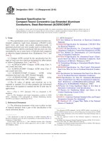
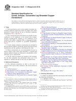
5.1 Peel Test Fixture—The fixture shall consist of a frame to
which the specimen is rigidly clamped, and a moveable beam
by which the tape is pulled off under a constant peel angle of
90 (Method A1 and B1) or 180° (Method A2 and B2). The peel
rate should be controllable between 20 mm/s and 200 mm/s for
Method A1 and B1 and between 14 mm/s and 140 mm/s for
Methods A2 and B2. A recording force gage is fitted between
the tape grip and the movable beam (see Fig. 1).
5.2 Pressure-Sensitive Tape—Unless otherwise specified in
the document referencing this test, the tape shall be 25 mm
wide, semitransparent, pressure-sensitive tape with an adhesion
strength of 43 6 5.6 g/mm or N/100 mm width when tested in
accordance with D3330/D3330M. The adhesion shall not
change by more than + 6.5 % of its mean value within 12
months. The backing of the tape may consist of fiber-reinforced
cellulose acetate, unplasticized poly (vinyl chloride), or polyester film. When results obtained in different laboratories do
not agree it is recommended that the test be repeated using tape
from the same batch.
3. Summary of Test Method
3.1 Pressure-sensitive tape is adhered to the surface of the
coating and then removed utilizing a motorized mechanical
device that peels the tape at a constantly maintained angle and
controlled rate of peel. A digital recording force gage is used to
record the maximum peel force.
NOTE 1—All due care must be taken to ensure that test specimens are
handled and stored such that they are not subjected to conditions that will
cause deleterious effects. These conditions include but are not limited to
handling without the use of gloves, storing in areas that accumulate dust,
areas of high humidity or where the sample may be subjected to fumes or
vapors that might condense on the sample.
5.3 Roller—The roller,4 which is hand operated, consists of
a steel roller 85 6 2.5 mm in diameter and 45 6 1.5 mm in
width, covered with rubber approximately 6 mm in thickness,
having a Shore scale A durometer hardness of 80 6 5. The
surface of the roller shall be a true cylinder void of any concave
or convex deviations. The mass of the roller shall be 2040 6 45
g.
3.2 Methods A1 and A2:
3.2.1 In these methods, which are nondestructive, the measurement area used is the unbroken coating surface with peel
angles of 90 and 180° respectively.
3.2.2 Adhesion is assessed in terms of “passed,” if the
coating does not detach, or “failed,” if the coating detaches
within the specified range of peel forces as recorded during the
test.
NOTE 2—A standardized roller is used in place of the pencil eraser of
Test Methods D3359 because of the variety of rubber and abrasives
formulations used to make pencil erasers. A further consideration was the
extended range of localized pressures that could be exerted by the pencil
and eraser.
3.3 Methods B1 and B2:
3.3.1 In these methods, which are destructive, the measurement area used is a broken coating surface created by scoring
a lattice pattern through the coating to the substrate and peeling
at angles of 90 and 180°, respectively.
3.3.2 Adhesion is assessed qualitatively on the 0 to 5 scale.
TEST METHOD A
NONDESTRUCTIVE, PARTS TAPE TEST
6. Test Specimen
6.1 Parts—This test normally is performed on parts. Any
requirements for test specimens will be found in the document
specifying their use.
4. Significance and Use
4.1 If a coating is to fulfill its function of protecting or
imparting unique properties to the surface of a substrate, it
must adhere to the substrate for the expected service life.
Because surface preparation (or lack of it) has a drastic effect
on adhesion of coatings, a test method for evaluating adhesion
to different surface treatments or of different coatings to the
same treatment is of considerable use to the industry.
NOTE 3—When specified by the document referencing this test, the
coated parts shall be subjected to a preliminary exposure, such as water
immersion, salt spray, or humidity, before conducting the tape test.
7. Procedure
7.1 Test Area—Select a flat area, on a significant surface,
free of blemishes and minor surface imperfections. Ensure that
the surface is clean and dry. Extremes in temperature or
relative humidity may affect the adhesion of the tape or the
coating.
4.2 The limitations of all adhesion methods, and the specific
limitation of this test method to lower levels of adhesion (see
1.3) should be recognized before using it. These test methods
are mechanized adaptations of Test Methods D3359; therefore,
the intra- and interlaboratory precision of these test methods
are similar to Test Methods D3359 and to other widelyaccepted tests for coated substrates, for example, Test Method
D2370, but this is partly the result of it being insensitive to all
but large differences in adhesion. The pass-fail scale of 0 to 5
for Method B1 and B2 was selected deliberately to avoid a
false impression of being sensitive.
7.2 Tape Section—Remove two complete laps of the
pressure-sensitive tape from the roll and discard. Remove an
4
The sole source of supply of the apparatus known to the committee at this time
is Pressure-Sensitive Tape Council (PSTC), 104 Wilmot Rd., Suite 201, Deerfield,
IL 60015. If you are aware of alternative suppliers, please provide this information
to ASTM International Headquarters. Your comments will receive careful consideration at a meeting of the responsible technical committee,1 which you may attend.
2
B905 − 00 (2016)
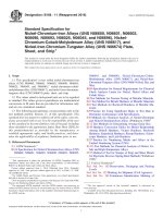
NOTE 1—Item 1 is the pneumatic cylinder traverse channel; 2 is the pneumatic pull cylinder; 3 is the pneumatic cylinder traverse which is shown in
the 90° pull position; 4 is the digital force gage, which is attached to the piston rod; 5 is the tape grip; 6 is the part/specimen hold down; 7 is the fixture
base; 8 is the free end of the tape; 9 is a coated specimen; 10 is the piston. By a simple displacement of the traverse, the fixture can be modified for 180°
testing. The pull rate is adjustable between 20 and 250 mm/s.
FIG. 1 Schematic of Tape Test Fixture
additional length at a steady (that is, not jerked) rate and cut a
piece off at least 100 mm long plus an additional length equal
to the space between the test surface and the grip on the fixture
for pulling the tape.
NOTE 5—At a peel angle of 90°, the peel rate of the tape from the
coating surface is equal to the pull rate, that is, the velocity by which the
free end of the tape is moved in the loading direction, whereas in a peel
angle of 180°, the peel rate of the tape is only half the pull rate.
7.5 Peel Force Control—Read the maximum value of peel
force recorded from the force registration gauge. If the force
value recorded is greater than 2.5 N 6 the force value specified
in the document referencing this test, the test shall be repeated.
Use a correspondingly lower or higher rate of peel until the
maximum value is within 62.5 N.
7.3 Tape Placement—Carefully place the tape on the area of
coating to be tested and lightly press and smooth the tape into
place, taking care to prevent any entrapment of air bubbles
between the tape and the coating. Once the tape is in place, roll
the tape firmly; once in each lengthwise direction (see 5.3). The
color under the semi-transparent tape is a useful indication of
when good contact has been made.
NOTE 6—For metallic coatings on polymeric substrates, the typical
force range is:
15 N – 25 N for Method A1
20 N – 35 N for Method A2
7.4 Time, Rate, and Angle:
7.4.1 Within 90 6 30 s of the tape application, fasten the
specimen onto the fixture, placing the free end of the tape in the
pulling grip. The apparatus should be set to maintain the
normal 90° peel angle, Method A1 (see Notes 4 and 5).
7.4.2 Pull the tape at a constant rate until only about 20 mm
of tape remains in contact with the coating. The residual
adhering tape can be removed manually after assessing adhesion on the area peeled off. This final removing of the residual
tape is not a constituent of the adhesion test.
7.6 Evaluation—Inspect both the area of coating and the
tape for evidence of flaking or detachment. Repeat the test at
another area of the part. Perform sufficient tests to ensure that
the adhesion evaluation is representative of the whole surface.
8. Report
8.1 The test report shall contain the following:
8.1.1 Method (A1 or A2),
8.1.2 Type of coating,
8.1.3 Any intermediate layers,
8.1.4 Substrate material,
NOTE 4—As far as possible, preference should be given to Method A1
(90° peel angle) due to the stress-strain behavior of the tape. If the coating
to be tested is not approachable for 90° testing, for example, at the wall
side inside a housing, Method A2 (180° peel angle) may be applied.
3
B905 − 00 (2016)
8.1.5
8.1.6
8.1.7
8.1.8
8.1.9
procedure to be tested to the panels of the composition and
surface conditions on which it is desired to determine adhesion.
Type of tape used,
Peel angle,
Rate of peel,
Any environmental exposure, and
Any failure at intermediate layers.
NOTE 7—Information on test panels and surface preparation methods
are given in Practices B183, B242, B254, B281, B320, B343, B481, B482,
B537, B629, B630, B727, D1730, D1731, and D1732; Guides B252,
B253, and B480; and Method B538.
8.2 Report the test results as:
p/F max
(1)
f/F max
(2)
12. Procedure
or
12.1 Test Area—Select an area free of blemishes and minor
surface imperfections. Assure that the surface is clean and dry.
Extremes in temperature or relative humidity may affect the
adhesion of the tape or the coating.
where:
p
= passed (no coating detachment),
f
= failed (coating detachment), and
Fmax = maximum registered peel force.
12.2 Scribing the First Series of Lines—Place the panel on
a firm base and under the illuminated magnifier make parallel
cuts as follows:
12.2.1 Space the cuts 4 mm apart and make six cuts (see
Note 8). Make all cuts about 20 mm long. Cut through the film
to the substrate in one steady motion using just sufficient
pressure on the cutting tool to have the cutting edge reach the
substrate. When making successive single cuts with the aid of
a guide, place the guide on the uncut area. After making the six
cuts, brush the film lightly with a soft brush or tissue to remove
any detached flakes or ribbons of coating.
9. Precision of Test Method A
9.1 An interlaboratory study of this test method reviewed
tape peel measurements on various coatings under several peel
conditions. The results showed that maximum peel force of the
tape depended significantly on the type of coating, the type of
tape, the peel rate and the peel angle. There was an insignificant relationship to the pressure used for adhering the tape to
the coating.
9.2 The results of coating adhesion assessments obtained on
different coatings should only be compared when the maximum deviation recorded, does not exceed 62.5 N.
NOTE 8—Scribed lines in metallic coatings often result in vertical
displacements from the coating surface. These displacements interfere
with the proper adhesion of the tape and the circumscribed areas
particularly when closer than 4 mm apart. This can result in questionable
adhesion passing this test.
9.3 The results of coating adhesion assessments obtained
with Method A1 should not be compared with the results
obtained with Method A2.
12.3 Scribing the Second Series of Lines—Prior to scribing
the second series of lines examine the cutting edge and, if
necessary, remove any flat spots or wire-edge by abrading
lightly on a fine oil stone. Cut the second series of six lines
spaced 4 mm apart at 90° to and centered on the first series of
lines (see Note 8). Brush the area as before and inspect the
incisions for reflection of light from the substrate. If the
substrate has not been reached make another grid in a different
location.
TEST METHOD B
DESTRUCTIVE, CROSS CUT TAPE TEST
FOR LABORATORY INVESTIGATION
10. Apparatus and Materials
10.1 In addition to the apparatus and materials in 5.1 the
following also are required:
10.1.1 Cutting Tool—A sharp razor blade, scalpel, knife or
other cutting device having a cutting edge angle between 15
and 30° that will make either a single cut or several cuts at
once. It is of particular importance that the cutting edge be in
good condition.
10.1.2 Cutting Guide—If cuts are made manually (as opposed to a mechanical apparatus) a steel or other hard metal
straight edge or template should be used to ensure straight cuts.
10.1.3 Rule—A tempered steel rule graduated in 0.5 mm
units is required for measuring individual cuts.
10.1.4 Illumination—A light source is recommended for
determining whether the cuts have been made through the film
to the substrate.
10.1.5 Magnifying Glass—An illuminated magnifier to be
used while making individual cuts and examining the test area.
12.4 Tape Section, see 7.2.
12.5 Tape Placement—Carefully place the tape over the
cross-hatch area of the coated test panel and lightly press and
smooth the tape into place, taking care to prevent any entrapment of air bubbles between the tape and the coating. Once the
tape is in place, roll the tape firmly once in each lengthwise
direction see 5.3). The color under the semitransparent tape is
a useful indication of when good contact has been made.
11. Test Specimen
12.6 Time, Rate, and Angle—Within 90 6 30 s of the tape
application, fasten the test panel onto the fixture placing the
free end of the tape in the pulling grip. The apparatus should be
set to maintain the normal 90° peel angle, Method B1 (see
Notes 4 and 8). Pull the tape at a constant rate until only about
20 mm of tape remains in contact with the coating. The residual
adhering tape can be removed manually after assessing adhesion on the area peeled off. This final removing of the residual
tape is not a constituent of the adhesion test.
11.1 Test panels shall be approximately 75 by 150 mm and
at least 0.4 mm thick. Apply the coating and preparation
NOTE 9—As far as possible, preference should be given to Method B1
(90° peel angle) due to the stress-strain behavior of the tape. If the coating
4
B905 − 00 (2016)
13. Report
to be tested is not approachable for 90° testing Method B2 (180° peel
angle) may be applied.
13.1 The test report shall contain the following information:
13.1.1 Method (B1 or B2),
13.1.2 Type of coating,
13.1.3 Any intermediate layers,
13.1.4 Substrate material,
13.1.5 Type of tape used,
13.1.6 Peel angle,
13.1.7 Rate of peel,
13.1.8 Any environmental exposure, and
13.1.9 Any failure at intermediate layers.
12.7 Peel Force Control, see 7.5.
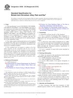
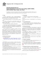
12.8 Evaluation—Using the illuminated magnifier, inspect
the grid area for removal of coating from the substrate or from
an intermediate coating. Rate the adhesion in accordance with
the following scale illustrated in Fig. 2 and described as
follows:
5
4
3
2
1
0
The edges of the cuts arc completely smooth; none of the
squares of the lattice are detached.
Small flakes of the coating are detached at intersections; less
than 5 % of the area is affected.
Small flakes of the coating are detached along edges and at
intersections of cuts. The area affected is 5 to 15 % of the
lattice.
The coating has flaked along the edges and on parts of the
squares. The area affected is 15 to 35 % of the lattice.
The coating has flaked along the edges of cuts in large ribbons
and whole squares have detached. The area affected is 35 to
65 % of the lattice.
Flaking and detachment worse than Grade 1.
13.2 Report the test results as follows:
C/Fmax
where:
C
F max
Repeat the test in two other locations on each test panel.
= Classification number according to Fig. 2, and
= maximum registered peel force.
FIG. 2 Example of Cross-Hatch Ratings
5
(3)
B905 − 00 (2016)
14. Precision of Method B
14.2 The results of coating adhesion assessments obtained
with Method B1 should not be compared with the results
obtained with Method B2.
14.1 The results of coating adhesion assessments obtained
on different coatings should only be compared when the
maximum deviation recorded, does not exceed 62.5 N.
ASTM International takes no position respecting the validity of any patent rights asserted in connection with any item mentioned
in this standard. Users of this standard are expressly advised that determination of the validity of any such patent rights, and the risk
of infringement of such rights, are entirely their own responsibility.
This standard is subject to revision at any time by the responsible technical committee and must be reviewed every five years and
if not revised, either reapproved or withdrawn. Your comments are invited either for revision of this standard or for additional standards
and should be addressed to ASTM International Headquarters. Your comments will receive careful consideration at a meeting of the
responsible technical committee, which you may attend. If you feel that your comments have not received a fair hearing you should
make your views known to the ASTM Committee on Standards, at the address shown below.
This standard is copyrighted by ASTM International, 100 Barr Harbor Drive, PO Box C700, West Conshohocken, PA 19428-2959,
United States. Individual reprints (single or multiple copies) of this standard may be obtained by contacting ASTM at the above
address or at 610-832-9585 (phone), 610-832-9555 (fax), or (e-mail); or through the ASTM website
(www.astm.org). Permission rights to photocopy the standard may also be secured from the Copyright Clearance Center, 222
Rosewood Drive, Danvers, MA 01923, Tel: (978) 646-2600; />
6