Astm c 522 03 (2016)
Bạn đang xem bản rút gọn của tài liệu. Xem và tải ngay bản đầy đủ của tài liệu tại đây (156.08 KB, 5 trang )
Designation: C522 − 03 (Reapproved 2016)
Standard Test Method for
Airflow Resistance of Acoustical Materials1
This standard is issued under the fixed designation C522; the number immediately following the designation indicates the year of
original adoption or, in the case of revision, the year of last revision. A number in parentheses indicates the year of last reapproval. A
superscript epsilon (´) indicates an editorial change since the last revision or reapproval.
C634 Terminology Relating to Building and Environmental
Acoustics
E691 Practice for Conducting an Interlaboratory Study to
Determine the Precision of a Test Method
1. Scope
1.1 This test method covers the measurement of airflow
resistance and the related measurements of specific airflow
resistance and airflow resistivity of porous materials that can be
used for the absorption and attenuation of sound. Materials
cover a range from thick boards or blankets to thin mats,
fabrics, papers, and screens. When the material is anisotropic,
provision is made for measurements along different axes of the
specimen.
3. Terminology
3.1 Definitions: The definitions used in this test method are
contained in Terminology C634.
3.2 Definitions of Terms Specific to This Standard: The
following items have been modified to exclude alternating
flow.
3.2.1 airflow resistance, R; mks acoustic ohm
(Pa·s/m 3)—the quotient of the air pressure difference across a
specimen divided by the volume velocity of airflow through the
specimen.
3.2.2 airflow resistivity, r0; mks rayl/m (Pa·s/m2)— of a
homogeneous material, the quotient of its specific airflow
resistance divided by its thickness.
3.2.3 lateral airflow resistivity— of an anisotropic homogeneous material, the airflow resistivity when the direction of
airflow is parallel to the face of the material from which the test
specimen is taken.
3.2.4 specific airflow resistance, r; mks rayl (Pa·s/m)—the
product of the airflow resistance of a specimen and its area.
This is equivalent to the air pressure difference across the
specimen divided by the linear velocity of airflow measured
outside the specimen.
3.2.5 transverse airflow resistivity— of an anisotropic homogeneous material, the airflow resistivity when the direction
of airflow is perpendicular to the face of the material from
which the test specimen is taken.
1.2 This test method is designed for the measurement of
values of specific airflow resistance ranging from 100 to
10 000 mks rayls (Pa·s/m) with linear airflow velocities ranging from 0.5 to 50 mm/s and pressure differences across the
specimen ranging from 0.1 to 250 Pa. The upper limit of this
range of linear airflow velocities is a point at which the airflow
through most porous materials is in partial or complete
transition from laminar to turbulent flow.
1.3 A procedure for accrediting a laboratory for the purposes of this test method is given in Annex A1.
1.4 The values stated in SI units are to be regarded as
standard. No other units of measurement are included in this
standard.
1.4.1 Table 1 is provided for user to convert into cgs units.
1.5 This standard does not purport to address all of the
safety concerns, if any, associated with its use. It is the
responsibility of the user of this standard to establish appropriate safety and health practices and determine the applicability of regulatory limitations prior to use.
2. Referenced Documents
2.1 ASTM Standards:2
E384 Test Method for Microindentation Hardness of Materials
3.3 Application of Terms:
3.3.1 The term airflow resistance can be applied to specimens of any kind.
3.3.2 The term specific airflow resistance has meaning only
when applied to a specimen of uniform thickness that is
homogeneous in directions parallel to its surface but not
necessarily homogeneous in the direction of airflow perpendicular to its surface.
3.3.3 The term airflow resistivity has meaning only when
applied to a specimen that is homogeneous in directions
parallel to a and perpendicular to its surface but not necessarily
isotropic.
1
This test method is under the jurisdiction of ASTM Committee E33 on Building
and Environmental Acoustics and is the direct responsibility of Subcommittee
E33.01 on Sound Absorption.
Current edition approved April 1, 2016. Published April 2016. Originally
approved in 1963. Last previous edition approved in 2009 as C522 – 03 (2009)ɛ1.
DOI: 10.1520/C0522-03R16.
2
For referenced ASTM standards, visit the ASTM website, www.astm.org, or
contact ASTM Customer Service at For Annual Book of ASTM
Standards volume information, refer to the standard’s Document Summary page on
the ASTM website.
Copyright © ASTM International, 100 Barr Harbor Drive, PO Box C700, West Conshohocken, PA 19428-2959. United States
1
C522 − 03 (2016)
TABLE 1 Conversion from cgs to mks and SI units
To convert from
cgs acoustic ohm
cgs rayl
cgs rayl/cm
cgs rayl/in.
mks rayl/in.
to
resistance is useful during product development, for quality
control during manufacture, and for specification purposes.
Multiply by
mks acoustic ohm (Pa·s/m3)
mks rayl (Pa·s/m)
mks rayl/m (Pa·s/m2)
mks rayl/m (Pa·s/m2)
mks rayl/m (Pa·s/m2)
105
10
103
394
39.4
5.2 Valid measurements are made only in the region of
laminar airflow where, aside from random measurement errors,
the airflow resistance (R = P ⁄U) is constant. When the airflow
is turbulent, the apparent airflow resistance increases with an
increase of volume velocity and the term “airflow resistance”
does not apply.
3.4 Symbols:
3.4.1 P = air pressure difference across test specimen, Pa.
3.4.2 U = volume velocity of airflow through the specimen,
m3/s.
3.4.3 u = U/S = linear velocity of airflow outside the
specimen, m/s.
3.4.4 S = area of specimen, m.2
3.4.5 T = thickness of specimen, m.
5.3 The specific airflow resistance measured by this test
method may differ from the specific resistance measured by the
impedance tube method in Test Method E384 for two reasons.
In the presence of sound, the particle velocity inside a porous
material is alternating while in this test method, the velocity is
constant and in one direction only. Also, the particle velocity
inside a porous material is not the same as the linear velocity
measured outside the specimen.
4. Summary of Test Method
4.1 This test method describes how to measure a steady flow
of air through a test specimen, how to measure the air pressure
difference across the specimen, and how to measure the
volume velocity of airflow through the specimen. From the
measurements may be calculated the airflow resistance, R, the
specific airflow resistance, r, and the airflow resistivity, r0.
6. Apparatus
5. Significance and Use
NOTE 1—It may be necessary to use a large surge tank or other means
to reduce pressure fluctuations.
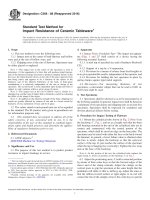
6.1 The apparatus, assembled as shown schematically in
Fig. 1, consists of the following components:
6.1.1 Air Supply, a suction generator or positive air supply
arranged to draw or force air at a uniform rate through the test
specimen.
5.1 The specific airflow resistance of an acoustical material
is one of the properties that determine its sound-absorptive and
sound-transmitting properties. Measurement of specific airflow
6.1.2 Flowmeter, to measure the volume velocity of airflow
through the specimen. It is preferable to have two or more
FIG. 1 Schematic Diagram of Airflow Apparatus
2
C522 − 03 (2016)
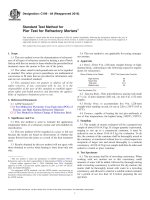
a diameter not less than 50 mm. For testing materials that will
support themselves, such as disks cut from boards, a slight
taper at the top of holder will enable the specimen to be pressed
into position with a tight fit. For testing materials that will not
support themselves, a removable screen held in position at least
25 mm above the mounting plate may be used alone or with a
plunger assembly that can compress the specimen to a known
thickness. For testing thin materials, such as fabrics or papers,
a flange at the top of the holder, together with a clamping ring,
will enable the specimen to be held securely for testing.
Specimens larger than the area of the holder can be tested with
suitable fittings attached to the end of the holder. In such cases,
care must be taken to ensure that the airflow through the edges
of the specimen is negligible in comparison to that through the
face.
flowmeters with overlapping ranges to enable different airflow
velocities to be measured to the same precision.
6.1.3 Differential Pressure Measuring Device, for measuring the static pressure difference between the faces of the
specimen with respect to atmosphere.
NOTE 2—A slant manometer or pressure transducer system with a range
from 0 to 250 Pa is usually satisfactory, but a second instrument with a
smaller range, for example, 0 to 25 Pa, may be necessary for measuring
small pressures to the desired precision.
6.1.4 Specimen-Mounting Assembly, consists essentially of
a mounting plate and a specimen holder as shown in Fig. 2. The
mounting plate has two holes for tube connections to the
pressure measuring device and to the airflow supply. The
specimen holder, which is sealed to the mounting plate, is
preferably a transparent plastic tube at least 150 mm long with
FIG. 2 Specimen Holder
3
C522 − 03 (2016)
NOTE 3—If measurements are made concurrently by the impedance
tube method, Test Method E384, the two instruments may conveniently
have the same inside diameter.
R 5 P/U
(1)
where P/U is the average value of ten or more readings made
in the region of laminar airflow.
7. Sampling
10.2 Calculate the specific airflow resistance in mks rayls
(Pa·s/m) from the expression:
7.1 Three or more specimens of a uniform sample material
should be tested. When the sample is not uniform the specimens should be selected to include the variations in the proper
proportion, or several representative specimens of the materials
should be tested and the results averaged.
r 5 SP/U
(2)
10.3 Calculate the airflow resistivity in mks rayls/m (Pa·s/
m2) from the expression:
r 0 5 SP/TU
8. Test Specimens
(3)
10.4 See Table 1 to convert from cgs to mks and SI units.
8.1 Boards—Relatively hard, firm materials at least 5 mm
thick. For transverse airflow resistance, disks are cut or sawed
from the sample with diameter to fit tightly into the specimen
holder. Coating the edges of the disks with grease may be
necessary to form an airtight seal between the specimen and the
holder wall. For lateral airflow resistance, several boards are
laminated together and a new board cut with faces at right
angles to the original faces of the boards. Disks cut from the
laminated board are tested in the usual manner.
11. Report
11.1 Report the following information:
11.1.1 Complete identification and description of the
material,
11.1.2 Type of test and mounting,
11.1.3 Description and dimensions of test specimen,
11.1.4 Conditioning procedure used, if any,
11.1.5 Number of specimens tested,
11.1.6 Individual and average values of test results, in mks
units, and
11.1.7 Temperature, barometric pressure, and relative humidity.
8.2 Blankets—Relatively soft, flexible materials at least 5
mm thick. Disks cut from the sample are laid on the removable
screen. If desired, the plunger assembly may be used to
compress the blanket to the desired thickness. Care must be
taken to prevent leakage around the edge of the specimen. A
transparent holder helps in spotting leaks.
11.2 If a test is made intentionally in the transitional or
turbulent airflow region, the reason should be given, and the
linear airflow velocities at which the measurements are made
shall be stated.
8.3 Sheets—Materials less than 5 mm thick. Disks with
diameter a little less than the outer diameter of the flange at the
top of the specimen holder are held in place with the clamping
ring with grease on the flange to limit the porous part of the
specimen to the inside diameter of the holder. Grease is also
used to prevent flow of air into the edges of the specimen.
Sheet materials with very low specific airflow resistance may
be tested by stacking layers of specimens separated with air
spaces to obtain a measurable pressure drop. The average result
for a single layer should be reported.
12. Precision and Bias
12.1 No quantitative statement on bias can be made at this
time since there is presently no material available with known
true values of performance, which can be used for determining
the bias of this test method.
12.2 The within- and between-laboratory precision of this
test method, expressed in terms of the within-laboratory, 95 %
Repeatability Interval, I(r), and the between-laboratory, 95 %,
Reproducibility Interval, I(R), is listed in Table 2. These
statistics are based on the results of a round-robin test program
involving seven laboratories.
9. Procedure
9.1 Mount the test specimen according to the type of test to
be made. Seal the specimen holder to the mounting plate and
adjust the airflow to give readable settings on the flowmeter
and pressure measuring device. Start at an airflow velocity well
below 50 mm/s. Record the differential pressure, P, the flow
rate, U, and the calculated quotient, R = P/U.
12.3 The significance of the Repeatability and Reproducibility Intervals is as follows:
12.3.1 Repeatability Interval, I(r)—In the same laboratory
on the same material, the absolute value of the difference in
two test results will be expected to exceed I(r) only about 5 %
of the time.
9.2 Repeat the measurements several times, using a larger
airflow rate each time. If the apparent resistance increases in a
steady way, the airflow is probably turbulent and the readings
must be discarded. Make a series of at least three measurements at well separated airflow velocities (25 % recommended
minimum differential) below the turbulent level.
TABLE 2 Within-Laboratory Repeatability, I(r), and BetweenLaboratory Reproducibility, I(R)
9.3 Measurements should be made where possible within a
temperature range of 22 6 5°C. No adjustment to the calculated results shall be made for barometric pressure.
Material
10. Calculation
10.1 Calculated the airflow resistance in mks acoustic ohms
(Pa·s/m3) from the expression:
Scotfelt foam
4
Avg
Specific
Repeat- Reproducibility
Airflow
ability
Resistance Uncertainty Uncertainty
(σR)
(MKS
(σr)
Rayls)
900.071
2.405
10.577
Repeatability
Interval
I(r)
Reproducibility
Interval
I(R)
6.735
29.616
C522 − 03 (2016)
12.3.2 Reproducibility Interval, I(R)—In different laboratories on the same material, the absolute value of the difference
in two test results will be expected to exceed I(R) only about
5 % of the time.
13. Keywords
13.1 absorption; acoustical materials; airflow resistance;
airflow resistivity
ANNEX
(Mandatory Information)
A1. LABORATORY ACCREDITATION
A1.1 Scope
writing by the manufacturer. If the pressure differential device
is not a fluid manometer it shall also be provided with a
calibration traceable to the National Institute of Standards and
Technology and shall be recalibrated at an interval stated by the
manufacturer.
A1.1.1 This annex describes procedures for accrediting a
testing laboratory to perform tests in accordance with this test
method. This annex was prepared in accordance with Guide
E717 and describes procedures.
A1.4.3 Procedures— The agency shall furnish a sample
report of a complete test (including raw data), showing
compliance with provisions of this test method as follows: 7.1
on Sampling, 9.1 on Specimen mounting, 9.2 on Repetitive
measurements, Section 10 on Required calculations, Report
requirements, paragraphs 11.1 and 11.2, and Section 12 on
Precision.
A1.2 Referenced Documents
A1.2.1 ASTM Standards:
E548 Guide for General Criteria Used for Evaluating Laboratory Competence2
E717 Guide for Preparation of Accreditation Annex of
Acoustical Test Standards2
NOTE A1.1—If the apparatus is calibrated in units other than the
customary metric units. The testing agency shall demonstrate the suitability of the conversion technique.
A1.3 General Requirements
A1.3.1 The testing agency shall make available to the
accrediting authority the information required by Sections 4 to
7 of Practice E548.
A1.4.4 Repeatability and Reproducibility—Results of repeated tests made on a particular reference specimen shall be
reported as a demonstration of the long term repeatability of
the test procedures. Each test should include mounting of the
test specimen. Care should be taken in selection of a suitable
reference specimen that will not be susceptable to damage
through multiple remountings and will not gradually be
clogged by airborne dust or other particles. The record shall
include all of the raw data, together with a statement of the
calculated precision showing conformance with 12.1, error
limitation.
A1.4 Requirements Specific to This Test Method
A1.4.1 Apparatus—The testing agency shall possess the
apparatus described in:
A1.4.1.1 Air Supply
A1.4.1.2 Flowmeter
A1.4.1.3 Differential Pressure Measuring Device
A1.4.1.4 Specimen-Mounting Assembly
A1.4.2 Calibration— There are several types of flowmeter
suitable for this test method. The testing agency shall provide
a valid calibration chart for the flowmeter, traceable to a
National Institute of Standards and Technology standard. The
flowmeter shall be calibrated at the interval recommended in
A1.4.5 To provide evidence of reproducibility in comparison with other testing laboratories it is preferable to use a
reference specimen for which test data are available from
several laboratories.
ASTM International takes no position respecting the validity of any patent rights asserted in connection with any item mentioned
in this standard. Users of this standard are expressly advised that determination of the validity of any such patent rights, and the risk
of infringement of such rights, are entirely their own responsibility.
This standard is subject to revision at any time by the responsible technical committee and must be reviewed every five years and
if not revised, either reapproved or withdrawn. Your comments are invited either for revision of this standard or for additional standards
and should be addressed to ASTM International Headquarters. Your comments will receive careful consideration at a meeting of the
responsible technical committee, which you may attend. If you feel that your comments have not received a fair hearing you should
make your views known to the ASTM Committee on Standards, at the address shown below.
This standard is copyrighted by ASTM International, 100 Barr Harbor Drive, PO Box C700, West Conshohocken, PA 19428-2959,
United States. Individual reprints (single or multiple copies) of this standard may be obtained by contacting ASTM at the above
address or at 610-832-9585 (phone), 610-832-9555 (fax), or (e-mail); or through the ASTM website
(www.astm.org). Permission rights to photocopy the standard may also be secured from the Copyright Clearance Center, 222
Rosewood Drive, Danvers, MA 01923, Tel: (978) 646-2600; />
5