Astm c 964 07 (2012)
Bạn đang xem bản rút gọn của tài liệu. Xem và tải ngay bản đầy đủ của tài liệu tại đây (329.42 KB, 11 trang )
Designation: C964 − 07 (Reapproved 2012)
Standard Guide for
Lock-Strip Gasket Glazing
1
This standard is issued under the fixed designation C964; the number immediately following the designation indicates the year of
original adoption or, in the case of revision, the year of last revision. A number in parentheses indicates the year of last reapproval. A
superscript epsilon (´) indicates an editorial change since the last revision or reapproval.
This standard has been approved for use by agencies of the U.S. Department of Defense.
Windows, Doors, Skylights and Curtain Walls by Uniform
Static Air Pressure Difference
E331 Test Method for Water Penetration of Exterior
Windows, Skylights, Doors, and Curtain Walls by Uniform Static Air Pressure Difference
1. Scope
1.1 This guide covers the use of lock-strip gaskets in
compliance with Specification C542 in walls of buildings not
over 15° from a vertical plane. The prime performance
considerations are weathertightness against air and water
infiltration, and structural integrity under wind loads. Included
are terminology, design considerations, and fabrication tolerances when using lock-strip gaskets in glazing applications.
3. Significance and Use
3.1 This guide provides information and guidelines for the
design of lock-strip gasket glazing systems. For related
standards, see Specifications C542, C716, and C963.
1.2 The values stated in SI units are to be regarded as the
standard. The inch-pound units in parentheses are for information only.
1.3 This standard does not purport to address all of the
safety concerns, if any, associated with its use. It is the
responsibility of the user of this standard to establish appropriate safety and health practices and determine the applicability of regulatory limitations prior to use.
4. Comparison to Other Standards
4.1 The committee with jurisdiction over this standard is not
aware of any comparable standards published by other organizations.
DESIGN CONSIDERATIONS
5. General
2. Referenced Documents
5.1 Structural integrity and watertightness of a gasket glazing system is dependent on interaction of the several components involved. These systems should be carefully designed
and built.
2.1 ASTM Standards:2
C542 Specification for Lock-Strip Gaskets
C716 Specification for Installing Lock-Strip Gaskets and
Infill Glazing Materials
C864 Specification for Dense Elastomeric Compression Seal
Gaskets, Setting Blocks, and Spacers
C963 Specification for Packaging, Identification, Shipment,
and Storage of Lock-Strip Gaskets
C1036 Specification for Flat Glass
E283 Test Method for Determining Rate of Air Leakage
Through Exterior Windows, Curtain Walls, and Doors
Under Specified Pressure Differences Across the Specimen
E330 Test Method for Structural Performance of Exterior
6. Components
6.1 The major components of lock-strip gasket glazing and
paneling systems are:
6.1.1 The supporting frame of metal, concrete, or other
structural building materials,
6.1.2 Lock-strip gasket, serving as an elastomeric mechanical seal and as a retainer for panel or glass, and
6.1.3 Glass or panel infill.
6.1.4 The design of these components and their accessories
are interrelated and the total system must be compatible.
7. Supporting Frames
1
This guide is under the jurisdiction of ASTM Committee C24 on Building Seals
and Sealants and is the direct responsibility of Subcommittee C24.73 on Compression Seal and Lock Strip Gaskets.
Current edition approved Dec. 1, 2012. Published December 2012. Originally
approved in 1981. Last previous edition approved in 2007 as C964 – 07. DOI:
10.1520/C0964-07R12.
2
For referenced ASTM standards, visit the ASTM website, www.astm.org, or
contact ASTM Customer Service at For Annual Book of ASTM
Standards volume information, refer to the standard’s Document Summary page on
the ASTM website.
7.1 Supporting frames are made of many materials, of
which the more common are aluminum, steel, and concrete.
7.1.1 Metal—Die marks, ridges, offsets, and scratches in
metal frames in contact with the gasket lips that could cause
leakage should be avoided. Metal in contact with any part of
the gasket should have sharp edges and burrs removed to avoid
the possibility of damage to the gaskets that could result in
Copyright © ASTM International, 100 Barr Harbor Drive, PO Box C700, West Conshohocken, PA 19428-2959. United States
1
C964 − 07 (2012)
corner butt joints are eliminated and the gasket lips make direct
contact with the concrete frame. With this concept it is
essential to have a continuous smooth surface free of voids or
honeycombing for the gasket lips to seal against because water
could bypass the gasket lip and enter under it. Also important
is to have a sharp arris at the corners of the concrete frame so
that the corners of the gasket lip can properly contact and seal
against the concrete. When plastic reglets are used, joints in
them could cause leaks unless sealed. When the gasket lips are
in direct contact with the concrete, meticulous casting procedures and close surveillance are required to assure a proper
finish along the contacting surface.
7.1.2.3 Frame Lug—It is difficult to achieve watertightness
with a gasket gripping the lug of a concrete frame as shown in
Fig. 2. Casting the lug to the 0.8-mm (61⁄32-in.) tolerance
required is unrealistic when dealing with concrete. Also,
casting it without a tapered draft for ease of form removal
results in complicated form work. A tapered draft provides
poor control over gasket lip pressure and results in a reduction
of pressure when excessive edge clearance permits the gasket
lips to slip to the narrower part of the lug. Unless the gasket
gripping the lug of a concrete frame has enough mass,
insufficient lip pressure against the concrete frame and leakage
could result because of the relatively large lug width.
7.1.3 Joints—Ideally, the best type of frame over which to
seat the gasket is one without joints. However, the realities of
construction should be recognized and dealt with. Watertightness between the lock-strip gasket and frame depends on
unbroken pressurized contact. Joints in metal, unless welded
and ground flush and smooth, make this concept difficult to
achieve. Members on either side of a butt joint should be
installed as true to plane as possible. If the design relies upon
sealed metal-to-metal joints, the small void between the gasket
lip and metal should also be sealed with a supplementary
sealant. A recommended safeguard is to have a built-in
drainage system within the frame. In this way, any water
penetrating the frame joints or gasket to frame joints will be
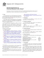
directed back to the outdoors. An aid towards minimizing the
possibility of water penetration between the gasket and frame
at static (fixed, nonmoving) metal joints in single openings
may be seen in Fig. 3. The direction of the joint is horizontal
between the horizontal and vertical members at the top of the
frame, and vertical between the horizontal and vertical members at the bottom of the frame.
structural failure through tear propagation. Weathering steel
frames used in gasket installations should be coated to prevent
corrosion on the surfaces covered by the gasket to a line not
less than 3.2 mm (1⁄8 in.) beyond the lip edge when installed.
7.1.2 Concrete—Gasket lips in contact with protrusions,
crazing, form marks, and offsets on concrete surfaces could
cause leakage and glass breakage and such irregularities should
be avoided. Concrete frames for lock-strip gaskets should be
jointless and are more suitable when precast, as the tolerances
and smooth surfaces required are too exacting for cast-in-place
concrete. Special forms and meticulous casting procedures are
required for optimum performance.
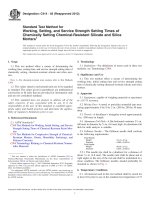
7.1.2.1 Corner Angles—Corner angles in the plane of the
glass should be held to 62° tolerance to properly receive the
gasket lips. See Fig. 1.
7.1.2.2 Reglets—It is essential that the recess in the concrete
be accurately cast so as to properly receive the spline of the
gasket. This can be accomplished with a plastic reglet that has
a removable weakness membrane as shown in Fig. 1. The
removable membrane maintains the proper recess shape and
keeps concrete out of the reglet while being cast. The removable membrane can be T-shaped, when desirable, with the stem
projecting from the reglet to provide a more convenient means
of attachment to the formwork of the concrete panel. After
casting, the weakness membrane is easily removed. Plastic
reglets are available with flanges extending beyond the gasket
lips, providing smooth contact surfaces. An advantage of the
plastic flange is the provision of a smooth rigid surface for
contact with the gasket lip. The plastic flanges are butted
together at the corners requiring a joint which should be
properly aligned and sealed. The exposed plastic flange should
be solidly cast into the concrete without any voids or honeycombing at the leading edge of the flange because water could
enter the interface between the flange and the concrete into
which it is cast. An advantage of the flangeless reglet is that the
exposed joint between the flange and the concrete as well as the
A
B
C
D
E
F
Sharp arris (no radius) required
Nominal angle ± 2° tolerance
Smooth surface required
6.4 mm (1⁄4 in.) minimum
Removable weakness membrane
Flange provides smooth surface at lip
NOTE 1—Insufficient mass at A and relative long distance from B to
lock-strip minimizes potential for adequate lip pressure at B.
FIG. 1 Reglet-type Gasket in Concrete
FIG. 2 Gasket Mounting on Concrete Lug
2
C964 − 07 (2012)
A
B
C
D
E
F
G
FIG. 3 Single-opening Metal Frame Joints for Increased Watertightness
7.1.4 Frame-to-Gasket Lips Clearance—Because lip pressure is critical in resisting the passage of water, the design of
the supporting frame must allow at least 3.2-mm (1⁄8-in.)
clearance between the installed gasket lip and any projecting
flanges or fillets. This allows the lips to exert unrestricted
pressure against the frame as shown in Fig. 4. Where the frame
lug and projecting flange form a fillet, the recommended
clearance should not include the convex portion.
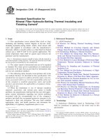
Hinge
Lock-strip
Lock-strip cavity
Lip (sealing edge)
Channel recess
Flange
Web
H
I
J
K
L
M
Glass or panel
Bite
Edge clearance
Frame-to-glass dimension
Frame lug
Frame
FIG. 5 Basic H-Type Gasket, its Functional Principles and Nomenclature
H-type gaskets are available that accommodate glass, panels,
and frame lug thicknesses ranging from 1.6 to 32 mm (1⁄16 to
11⁄4 in.). Gaskets accommodating thicknesses greater than 32
mm (11⁄4 in.) are also available. Thick panels should not be
mounted on relatively thin lugs as the weight of the glass or
panel cannot be supported properly. The best performance can
be expected where the lug thickness equals or exceeds the
thickness of the glass or panel. There are exceptions to this
recommendation which are dependent upon other factors, such
as lightweight panels, extremely small openings, or situations
where total performance is not required. Acceptable deviations
require engineering analysis, consultation with the gasket
manufacturer, and testing.
8.1.1.2 Reglet Type—The reglet-type gasket is a patented
type whose functional principles and nomenclature are illustrated in Fig. 6. Reglet-type gaskets are designed with a spline
8. Gaskets and Accessories
8.1 To accommodate the wide variety of glass and panel
thicknesses available as well as allow for mounting to various
types of framing members, a wide variety of gasket cross
sections are produced by the extrusion manufacturing process.
The technique of extruding varies among the manufacturers,
and has a limiting factor on the complexity of cross-section
designs produced.
8.1.1 Gasket Types—Lock-strip gaskets are typically identified by their general cross-section configuration. The most
common are H-type and reglet type. Other special and proprietary interlocking types have been developed as a result of
modifications to the basic types, usually because of provisions
for mounting or mating to special framing members. Gasket
sections are generally of two types: the perimeter section and
the muntin section.
8.1.1.1 H-Type—The basic H-type gasket, its installation,
and nomenclature are illustrated in Fig. 5. After the gasket is
installed over the frame and the glass or panel infill installed in
the gasket, the lock-strip, which is of higher durometer, is
forced into a groove in the gasket. A resultant compressive
force is transferred to the lips which apply pressure to the
frame and glass. Sufficient lip pressure against smooth surfaces
creates an effective weathertight seal. A wide selection of
A
B
C
D
E
F
G
Hinge
Lock-strip
Lock-strip cavity
Lip (sealing edge)
Channel recess
Flange
Web
H
I
J
K
L
M
Glass or panel
Bite
Edge clearance
Frame-to-glass dimension
Spline
Reglet
FIG. 6 Reglet-type Gasket, its Functional Principles and Nomenclature
FIG. 4 Gasket Mounting Clearance
3
C964 − 07 (2012)
water. This may be the case with a corner having square lips on
the frame side where, because of the longer diagonal distance
to the lock-strip, little or no lip pressure may be obtained at the
apex. It should not be assumed that passage of the lip pressure
test in Specification C542 provides assurance that the gasket is
adequate for resistance to the passage of water. Gasket corner
designs having square lip seals are not as common as previously. Gaskets having approximately 6.4 mm (1⁄4 in.) radius at
the external corner lips are now available. With such a design,
a more uniform edge distance is maintained from the lip edge
to the lock-strip as shown in Fig. 8. In this way, lip pressure is
not generally reduced around the corner as with a square lip
because of the appreciably longer moment arm. Generally, the
round lip is concealed by an external noncontacting square lip
for appearance but the seal is provided by the contacting round
lip. The angle of the gasket molded corner should conform
within 5° to the corner angle of the frame. Molded corner
angles of less than 45° should be avoided as the insertion of an
extremely acute corner angle is impossible without damage to
the molded corner or panel unit.
8.1.2.2 Tees and Crosses—Tees permit the juncture of the
perimeter member of a gasket to a muntin member. Crosses
allow for division of a glazed area horizontally and vertically.
Crosses and tees can be injection molded as well as corners.
The corner angle conformation tolerance of 65° is also a
requirement for tees and crosses.
8.1.2.3 Butted Joints—Where feasible, long sections of
gaskets should be joined end to end by factory-injection
molding. Where field-butted joints are required, an application
of sealant or adhesive recommended by the gasket manufacturer should be used in the joint under compression to achieve
weathertightness.
8.1.3 Lock-Strips—The purpose of lock-strips is to apply
pressure to the gasket sealing lips, causing the lips to grip and
seal against both the frame and the glass or panel. Lock-strips
may be separate from, or an integral part of, the gasket proper.
The separate lock-strip should be 10 points harder in durometer
(A scale) than the gasket itself. The additional hardness of the
lock-strip resists deformation under compression and maintains
the designed gasket lip pressure for longer periods than would
a lock-strip of equal size of a lower durometer.
8.1.4 Gasket Systems—A gasket system is produced when
perimeter gaskets and muntin gaskets are assembled and
designed to mate with corresponding frame members as a total
unit. Gasket systems are referred to as (a) supported, in which
all the muntin members are metal supported gasket members;
or (b) unsupported, in which vertical muntin gaskets are
unsupported by metal members. Supported systems should be
used where optimum performance is required.
8.1.4.1 H-Type System—An H-type system uses an H-type
gasket for the perimeter as well as for the muntins. This system
permits using a glass panel and a spandrel panel, or a glass
panel and a panel containing an operating window insert, in the
same system. The gasket manufacturer should be consulted
prior to designing such a system, to ensure that perimeter and
muntin gaskets are compatible and can be joined together to
produce a favorable system.
that fits into a reglet. The seal against the frame is accomplished by forcing the spline of the gasket into the reglet so that
the fins on the side of the spline retain the gasket in the reglet
and thus hold the sealing lips of the gasket tightly against the
frame surface. The seal against the glass or panel is accomplished by the insertion of the lock-strip as with the H-type
gasket. Most reglet-type gaskets are designed to fit into a reglet
that is 19 mm (3⁄4 in.) deep and 16 mm (5⁄8 in.) wide. If the
reglet is of lesser depth, the gasket will “bottom-out” and not
provide a proper installation. If the reglet is too wide, the
gasket will not be held in place properly and thereby provide
difficult glass or panel installation. If the reglet is too narrow,
the gasket will be difficult to install. Reglet-type gaskets are
available that accommodate glass or panel thicknesses from 1.6
through 32 mm (1⁄16 through 11⁄4 in.). There is an important
basic difference between the H-type and reglet-type gaskets
that should not be overlooked in field application. The lockstrip of both gaskets causes lip pressure against the frame and
glass, but with the reglet-type gasket, lip pressure is also
affected by the depth of the gasket spline in the reglet. This is
controlled by the installer at the site as well as by the geometry
of the gasket and reglet. Available are reglet-type gaskets that
have projecting offsets at the upper or lower part of the spline.
These are designed to control the depth at which the spline is
inserted into the reglet.
8.1.1.3 Special Interlocking and Proprietary Types—In addition to the basic H-type and reglet-type gaskets, there are
various special interlocking and proprietary type gaskets.
Several of these are illustrated in Fig. 7. The basic principle of
the interlocking type is to achieve greater roll-off resistance of
the gasket from the frame by mechanically interlocking the
gasket to the frame.
8.1.2 Gasket Joints—Best sealing performance is achieved
with a continuous gasket having factory-formed injectionmolded joints. In the use of discontinuous ladder-type gaskets
or stick systems (assembled in the field, using cut lengths),
achieving a weathertight seal requires a field application of
sealant or adhesive recommended by the gasket manufacturer.
Geometric continuity should be achieved at the juncture of
extrusion and molded joint. Sharp offsets, the limits of which
have not as yet been established, can break the continuity of the
lip seal and prevent or reduce water tightness.
8.1.2.1 Corners—Continuous and adequate lip pressure provided by the gasket against frame and glass is a key factor in
the design of the gasket for watertightness. A pressure of 7
N/linear cm (4 lbf/linear in.) has been determined to be the
minimum that will satisfy this requirement. However, of
utmost importance is the requirement that this pressure be
continuous and uniform at every point along the lip of the
gasket. The present lip pressure test in Specification C542 is a
test for average lip pressure over the entire test specimen
length. When applied to the extruded portion of the gasket, it
can reasonably be assumed that the pressure would be continuous and uniform at every point, provided the gasket lips are not
damaged. This is not necessarily true of the molded corners.
Gaskets of various corner designs can pass the lip pressure test,
but not all have the capability of sealing out the passage of
4
C964 − 07 (2012)
AB
CFG
D
EH
—Horizontal members
—Vertical member for lateral support
—Horizontal or vertical perimeter member
—Horizontal or vertical members
FIG. 7 Special Interlocking and Proprietary Type Gaskets
particularly if the opening is of concrete. The tolerances
published by the gasket manufacturer for reglet-type systems
should be followed.
8.1.4.3 Stick System—A stick system incorporates gaskets
that are straight lengths of extrusions cut to size and joined
during installation in the field. Manufacturer’s recommendations should be followed regarding the installation techniques
to be used as well as the type and location of adhesives or
sealants to be used for the joints.
8.1.4.4 Ladder Assembly System—A ladder assembly system is produced by vulcanizing muntin gasket extrusions to
perimeter gasket extrusions with the use of an injection-molded
Tee-joint. These may be vertical or horizontal ladder assembly
systems as shown in Fig. 9. Production experience shows that
a ladder gasket assembly larger than 20 ft (6.1 m) in length
FIG. 8 Gasket Corner Design Features
8.1.4.2 Reglet-Type System—A reglet-type system typically
includes a reglet-type gasket for the perimeter and a supported
or unsupported H-type gasket for the muntins. The reglet type
systems require a greater control over the opening dimensions,
5
C964 − 07 (2012)
deterioration of it, the gasket, or the glass or panel infill and in
compliance with Specification C864.
8.1.5.2 Location—A continuous strip or two setting blocks
at the quarter points are permissible, provided the maximum
pressure described in 8.1.5.3 is not exceeded. The continuous
strip should be cut short of the width by 102 mm (4 in.).
8.1.5.3 Width—The width of setting blocks should be 1.27
mm (0.05 in.) less than the nominal glass or panel thickness.
Less width could result in improper support for the glass or
panel. Greater width could result in a loss of weathertightness
as illustrated in Fig. 10.
8.1.5.4 Depth—The depth of setting blocks should be such
as to vertically center the panel in the gasket opening thus
equalizing the clearances on top and bottom. However, edge
clearance should not be increased to the extent that required
push-out capacity is jeopardized (see 10.1.1).
8.1.5.5 Length—The total cumulative length of the setting
blocks should be a minimum of L as defined herein, and a
maximum of the opening width less 102 mm (4 in.), so as to
ensure a minimum expansion of the gasket web at the pressure
points.
FIG. 9 Gasket Systems
becomes too difficult to fabricate or handle. Field installation
problems are also encountered. Where large areas are to be
glazed using the ladder gasket assembly, the assemblies are
produced in conveniently sized sections, and joined in the field.
Joining is accomplished by butting under compression
(“crowding”) the free ends of the gaskets together. A weathertight seal can be accomplished by the injection of an appropriate adhesive or sealant recommended by the gasket manufacturer in the butted gasket joint after the unit is glazed and
lock-strip inserted. In horizontal ladder systems where the
vertical gasket member is unsupported the vertical gasket is
used only as a weather seal and does not provide any
significant structural support to the vertical glass edges. For
vertical ladder systems the horizontal gasket members must be
supported (see 10.1.10.4).
8.1.4.5 Grid Assembly System—A grid assembly system is
one in which horizontal and vertical muntin gaskets intersect
within the perimeter gaskets as shown in Fig. 9. Intersecting
muntin gaskets are assembled by a molded joint. All grid
systems should be of the supported type.
8.1.5 Setting Blocks—The purpose of setting blocks is to
provide positive support, but prevent direct contact between
the bottom of the glass or panel and the web of the sill gasket
member. A certain amount of vertical edge clearance is
required in order to install the gasket without tearing the upper
corners of the gasket. If the glass or panel were to be installed
directly onto the web of the sill gasket member, too much edge
clearance would be left at the head member. With setting
blocks, the glass or panel can be lowered down to the web of
the sill member for easier glass insertion at the head and then
raised within the gasket enclosure for insertion of setting
blocks to provide the desired edge clearance space at the sill
member before the lock-strip is installed. Factors to consider in
the use of setting blocks are (a) compatibility of materials, (b)
location and quantity, (c) avoidance of support at the gasket
corners, (d) maximum pressure permitted on the gasketbearing surface under the setting blocks, and (e) geometry of
the setting blocks with regard to the gasket, to the gasket cross
section, and glass or panel width.
8.1.5.1 Material—The setting block material should be an
elastomer of durometer (A scale) of 85 6 5, of rectangular
cross section, dimensionally stable, causing no interactive
L 5 W/PT
where:
L
=
W =
T
=
P
=
total cumulative length of setting blocks, mm (in.),
weight of glass or panel, kg (lb),
thickness of glass or panel, mm (in.), and
bearing pressure of glass or panel on setting blocks,
max = 103 kPa (15 psi).
8.1.6 Edge Spacers—When installing unsupported vertical
ladder assembly gasket systems, installation of a continuous
rubber edge spacer is required between the head of each glass
or panel and the web of the gasket muntin above. This
procedure maintains the muntin center line at its proper
elevation during installation and to prevent the possibility of
future settling of stacked lights. The configuration and durometer (A scale) of the edge spacers should be as recommended
by the manufacturer of the gaskets but no less than that of the
gasket.
8.1.7 Weepholes—Weepholes in the sill portion of the gasket
can be used to drain away water that has entered between the
gasket lips and glass during driving rain and gusting winds.
Glass manufacturers require that weepholes be used with
insulating, wired, and laminated glass, as water trapped in the
gasket channel can have deterimental effects on such units.
Weepholes in single glazing is optional.
FIG. 10 Effect on Gasket Caused by Too Wide or Overloaded
Setting Blocks
6
C964 − 07 (2012)
tempered), insulating, and laminated glass of three or more
plies. Other types should not be altered by the glazier unless a
good clean-cut edge is assured. Nipping, grinding and, in some
cases, seaming of the edges should not be permitted (see
10.1.4). Other requirements are as follows:
(a) Insulating Glass—The dimensions of insulating glass
cannot be altered after fabrication. Some insulating glasses
were fabricated with a protective or structural metal edge
channel. The channel serves a definite purpose and should not
be removed if resetting the glazing; as under most conditions,
removal of the edge channel voids the manufacturer’s warranty.
(b) Tinted and Coated Glasses—Tinted (gray, bronze, and
green) and coated glasses, both single and laminated, are
furnished with factory edges which may vary with
manufacturers, glass types, and thicknesses. In each case the
edgework represents the manufacturer’s best judgment. Field
cutting should be avoided, but when necessary only a clean-cut
edge should be allowed. When acceptable to the glass
manufacturer, scarfing or rounding of the corners (intersections
of edges) of the glass may be done, using a 180-grit or finer
emery cloth or sandpaper to help prevent damage to the
gaskets.
(c) Clear Glass—Regular plate or float and sheet glasses
can be successfully field cut, provided sufficient glass is
removed to prevent nipping and “run-outs.” Their edges may
be seamed and their corners scarfed, provided a fine emery
cloth or sandpaper (180-grit or finer) is used. Cut sizes supplied
by the manufacturers normally are clean-cut. In some cases
large lights of heavy-duty glass may have special factory
edges.
(d) Heat-Strengthened and Tempered Glasses—These
types of glass are usually furnished with seamed edges. Edge
or corner treatment must be accomplished before tempering.
After fabrication, edges (including corners) should not be
modified in any way.
(e) Patterned Glasses—Patterned glasses with a deep pattern cannot be installed in gaskets with good assurance against
water infiltration. When this type is being considered, the
feasibility of using a gasket system can best be determined by
assembly testing.
9.1.1.2 Bite—For tinted and coated glasses, both monolithic
and insulating, the following maximum bites on the glass
should be adhered to as closely as possible. Excessive bite may
result in serious thermal stresses which may materially contribute to glass breakage, especially when other stresses are
simultaneously placed on the glass. Minimum bite is governed
by the maximum edge clearance permitted for structural
reasons (see 10.1.1).
8.1.7.1 Size and Location—Weepholes, when used, should
be 6.4 to 9.4 mm (1⁄4 to 3⁄8 in.) in diameter and at least three per
opening with one at the center and one at each end between
setting block and corner. Whenever possible, provide the
weepholes in the web of the gasket so that the water can drain
down into the frame and then be channeled outward, in
preference to draining outward through the flange of the
gasket, as shown in Fig. 11. Weepholes in the flange permit
unwanted water to drain outward but can conceivably also
permit water to enter from one side of the system to the other
under certain conditions of pressure differential. On the other
hand, weepholes could possibly serve to reduce pressure
differential within the system. The use of an open-cell polyurethane pad behind each weephole in the metal frame keeps
out insects and excessive water penetration while still permitting water to drain gradually back to the outside. When
reglet-type gaskets are used, it is recommended that the reglet
also be drained to the exterior where feasible. This can be
achieved with plastic drain tubes. A minimum of two tubes are
recommended with a 9.4-mm (3⁄8-in.) inside diameter. Assembly testing can best determine the effect of weepholes in the
system.
9. Infill Materials
9.1 The more predominant materials placed into and
gripped by lock-strip gaskets are glass, plastic sheet materials,
and a variety of panels.
9.1.1 Glass—The numerous factors affecting the structural
integrity of glass when used in lock-strip gasket glazing
systems make it advisable that the glass manufacturer be
consulted for glass selection and strength of the product to be
used. The basic strength characteristics of glass products,
particularly tinted and coated glasses, are affected by perimeter
treatment and bite. Their influence on the structural performance of the entire system are described under 10.1.4.
9.1.1.1 Edge Treatment—The edges of many types of glass
cannot be altered after fabrication. These types include heatstrengthened, tempered, spandrel (heat-strengthened or
A
B
C
D
E
Glass Thickness, mm (in.)
6.4 (1⁄4) or thinner
9.4 (3⁄8)
12.7 (1⁄2)
Insulating glass
Setting blocks at 1⁄4 points
Weepholes not covered by setting blocks (center between and
on each side of blocks near jambs)
Weepholes in frame
Open-cell polyurethane pad behind each weephole in frame
6.4 mm (1⁄4 in.) minimum clearance when pad is in line with
weephole above
Maximum Bite, mm (in.)
9.4 (3⁄8)
11 (7⁄16)
12.7 (1⁄2)
14.2 (9⁄16)
Some manufacturers will permit greater bite than 14.2 mm
(9⁄16 in.) for insulating glass (particularly when tempered) but
should be confirmed by the manufacturer.
FIG. 11 Gasket Drainage Systems
7
C964 − 07 (2012)
face of the panel by more than 3.2 mm (1⁄8 in.) so that it does
not interfere with the contact of the gasket lips against the
panel.
9.1.3.4 Surface Smoothness—Surfaces should be smooth
and free of offsets around the perimeter, where contacted by the
gasket.
9.1.3.5 Insulated Panels—Insulated sheet metal panels
should have the facing metal flanged and overlapped at edges
to avoid contact of sharp edges and corners with the gasket.
9.1.3.6 Weight—The weight of the panel should be so
limited that the load transmitted to the gasket web at the bottom
of the panel is no greater than 103 kPa (15 psi) unless permitted
by the gasket manufacturer.
9.1.3.7 Weepage—Provide weepholes in gaskets retaining
insulated metal panels or those which have unprotected cores
which can be damaged with moisture.
9.1.1.3 Strength Criteria in Unsupported Gasket
Members—In multiple-opening gasket systems, unsupported
members do not provide any significant stiffening influence
(see 8.1.4). Insulated units are not to be used in unsupported
gasket systems. They require metal or other type structural
members on all edges. Also, monolithic glass thickness and
strength for such openings must be chosen to meet two-side or
three-side support conditions. This usually requires significant
increases in glass thickness or heat strengthening or tempering
of the glass.
9.1.2 Sheet Plastic—Because of the greater coefficient of
expansion and greater flexibility of plastic compared to glass,
the criteria for glass cannot be used for sheet plastic.
9.1.2.1 Flexibility—Acrylic and polycarbonate sheets are
extremely flexible in sizes and thicknesses normally used in
glazing installations. This should be considered in evaluating
the resistance to push-out afforded by the gasket. Specific data
regarding deflections of sizes and thicknesses and minimum
bite to be used should be obtained from the plastic manufacturer.
9.1.2.2 Use of Solvents—Many common solvents such as
gasoline, benzene, and acetone, will cause deterioration of the
surface of acrylic and polycarbonate sheets. The plastic manufacturer should be consulted and his instructions followed,
regarding acceptable cleaning materials harmful to the surface
of the plastic.
9.1.2.3 Thermal Expansion—Reference should be made to
the manufacturer’s literature regarding provisions for thermal
expansion of the plastics. In large sizes the edge clearances
required for expansion prohibit the use of standard gasket cross
sections.
9.1.2.4 Edge Treatment—Sheet plastics are not notchsensitive, and treatment of edges is not as significant as for
glass. Edges may be sawed and seamed. Apparent fissures or
cracks at the edge, however, are cause for rejection.
9.1.2.5 Tolerances—Dimensional and thickness tolerances
for acrylic and polycarbonate sheets for glazing are available
from the manufacturer. There are not established standards in
this regard, and early consultation with the plastics manufacturer is recommended.
9.1.3 Panels—Metal and various other laminated materials
can be installed and held weathertight in lock-strip gaskets.
Criteria for use are generally the same as for glass. In addition,
the following requirements govern the use of panels:
9.1.3.1 Edge Strength—Edge strength should be adequate
for gasket glazing to prevent crushing during insertion and to
resist permanent deformation when loaded.
9.1.3.2 Corrosion Protection—Surfaces should be noncorrosive or protected with a noncorrosive coating. Weathering
steel should have the portion hidden in the gasket plus a
minimum of 3.2 mm (1⁄8 in.) exposed surface coated with a
protective coating.
9.1.3.3 Edge and Corner Treatment—No sharp edges or
corners should be permitted unless protection is provided.
Wherever possible, corners should be rounded. A suitable tape
is feasible for protection against sharp edges but not against
sharp corners. When used, the tape should not extend onto the
10. Factors Affecting Performance
10.1 Since lock-strip gaskets are elastomeric mechanical
seals that grip the supporting frame and glass or panel infill,
structural performance is of prime importance, and all factors
that affect such performance must be considered in the design
of a lock-strip gasket glazing system. In addition to glass or
panel strength, the more critical factors are edge clearance,
bite, centering of glass or panel, glass edges and corners,
deflection of glass or panel lubricants, gasket design, gasket
fabrication, frame and glass tolerances, and supporting frame
design.
10.1.1 Edge Clearance—Investigations and reports of various tests performed to date indicate that glass-to-web and
frame-to-web edge clearances, with the resultant frame-toglass distance, is an extremely important factor in determining
the structural capacity of the gasket to resist push-out of the
glass from the gasket or roll-off of the gasket from the
supporting frame when subjected to wind loads. The greater
the frame-to-glass dimensions, the more critical becomes the
structural capacity of the gasket to resist push-out or roll-off.
This can be analyzed by observing Fig. 12, which is a
schematic drawing representing the configuration of the gasket
under load. P is the resultant unit load imposed on the lips of
the gasket from wind loads acting on the glass, and D is the
distance between the glass edge and the supporting frame. The
gasket is flexible, but must have sufficient flexural strength to
resist, within acceptable limits of flexure, the moment developed as a product of P and D. With P being a constant for a
given load on the glass, it can be seen that the variable D
becomes a critical factor relative to the structural capacity of
the gasket. The gasket clearance, as measured after the installation is complete, must ensure sufficient grip of gasket lips on
both the supporting frame and panel or glass. For economical
installations and prevention of tearing of the premolded corner
in the process, this clearance should be as large as possible, but
for maximum strength and weathertightness a minimum clearance is preferable. Any subsequent differential movement or
dimensional change of supporting frame and infill panel or
glass should result in a gasket clearance that is neither beyond
the maximum design value nor zero. Nominal clearance around
all sides of the panel or glass should ideally be 3.2 mm (1⁄8 in.)
with the bottom clearance being maintained by setting blocks.
8
C964 − 07 (2012)
p
P
D
PD
mally the weakest point in push-out or roll-off resistance
occurs where the clearance is the greatest. Setting blocks are
recommended so that the glass can be centered vertically.
Dynamic wind loads and movement of frame members can
cause the glass to shift off center. A possible aid in preventing
this could be the insertion of continuous edge spacers between
the glass edges and the gasket web at the jambs. These can be
difficult to install, however, since they must be inserted after
the glass is in place and before the lock-strip is secured.
Although no test data presently exist, a feasible compromise
could possibly be to insert short strips of edge spacers in the
vertical portion of the lower corners and molded L-shaped
spacers around the upper corners of the glass. The horizontal
upper leg would prevent the vertical lower leg from dropping
down. With either method, the size, shape, and compressibility
of the edge spacers must be carefully sized to avoid decreasing
the necessary lip pressure against the glass.
10.1.4 Glass Edges and Corners—Seaming glass edges to
reduce their sharpness can reduce the strength of glass significantly and, contradictory as it may appear, the process of
seaming glass edges so that they feel smooth to the touch
actually creates numerous minute cuts or weakness points.
Glass manufacturers will in some cases, as for thinner lights of
ordinary clear glass, condone seaming edges but should be
consulted as to feasibility and method (see 9.1.1.1). Since
thermal stresses are greatest at the center of the glass edges and
approach zero at the corners, some glass manufacturers will
permit the corners to be rounded slightly. When acceptable to
the glass manufacturer, this is an important aid to the installation of the glass with minimum edge clearance and eliminates
the possibility of sharp corners cutting the lips or web of the
gasket. When considered desirable, the gasket can be protected
against the sharp edges of clean cut glass by taping them with
a suitable tape. However, the tape should not extend onto the
surface of the glass by more than 3.2 mm (1⁄8 in.) so that it does
not interfere with the contact of the gasket lips against the
glass. Rounding of corners would not apply to insulating glass.
10.1.5 Deflection of Glass—On large lights of glass, having
thicknesses of 6.4 mm (1⁄4 in.) or under, large deflections occur
under wind loading at the center of the glass in a direction
perpendicular to the plane of the glass. This increases edge
clearance and thereby reduces the push-out resistance of the
gasket.
10.1.6 Lubricants—Lubricants are useful, and even
essential, for facilitating the installation of gasket glazing
systems. However, when lubricants are carelessly applied and
are placed on the gripping surfaces of the frame, gasket, and
glass, serious reductions in structural performance can result.
Since the installation is made easier with lubricants, it stands to
reason that push-out or roll-off resistance is decreased. Lubricants should be compatible, nonstaining products that ideally
will evaporate and become ineffective soon after placement.
Lubricants exposed to the exterior generally evaporate and
become ineffective soon after placement, but this is not
necessarily true where the lubricants are literally bottled up in
the critical gasket channels that receive the glass and frame.
The lock-strip cavity should be lubricated to ease the installation of the lock-strip and does no harm. There is no reason to
Unit area load on glass
Resultant linear load on gasket
Frame-to-glass edge dimension
Moment to be resisted by the gasket
FIG. 12 Roll-off Forces Acting on Gasket
10.1.1.1 Structural Capacity and Lip Pressure—Structural
capacity of a gasket to resist push-out or roll-off should not be
confused with lip pressure values. Specification C542 requires
that the lip pressure of a gasket should be a minimum of 7
N/linear cm (4 lbf/linear in.) to provide an adequate and lasting
seal. It should not be assumed that a gasket meeting this
requirement has sufficient structural capacity to resist 7
N/linear cm (4 lbf/linear in.) of push-out or roll-off pressure. It
may be able to resist more or less pressure depending on
several factors, including the amount of edge clearance which
is of major importance.
10.1.1.2 Design Limits—The resultant average unit load on
the gasket, determined by dividing the total load on the
contained glass or panel by the perimeter length, increases
more rapidly when related to area increase than when related to
perimeter increase. The larger areas and thicker lights of glass,
therefore, more critically affect the ability of the gasket to resist
roll-off. Although there are many factors to consider, tentative
design criteria presently advocated by glass and gasket manufacturers for basic H-type gaskets with normal four-side
support is to limit their use with flat glass having a thickness of
9.4 mm (3⁄8 in.) and under to a maximum opening area of 9.29
m2 (100 ft2) and to limit their use with flat glass 12.7 mm (1⁄2
in.) or more in thickness to a maximum opening of 5.57 m 2
(60 ft2). These data are based on a standard glass wind load
performance chart utilizing a 2.5 design factor.
10.1.2 Bite—With the gasket snugged to the frame, the
minimum bite or grip on the panel or single glass should be 6.4
mm (1⁄4 in.) and 3.2 mm (1⁄8 in.) beyond the metal edging on
insulated glass even though published design push-out resistance of the gasket selected may otherwise be determined
adequate.
10.1.3 Centering of Glass or Panel—To achieve optimum
structural performance, the glass should be centered in the
opening. Since edge clearance is an important factor, centering
the glass will give uniform edge clearance all around. Nor9
C964 − 07 (2012)
and roll-off resistance. It is essential, therefore, that acceptable
tolerances for both frame and glass be established for each
project and complied with, so that edge clearance does not
exceed acceptable limits. The glass manufacturers are in
general agreement on the dimensional tolerances of insulating
glass as well as the cutting tolerances of flat glass and have
published applicable data for their products. For flat glass,
tolerances established in Specification C1036 must be complied with to be compatible with gaskets in compliance with
Specification C542. For insulating glass tolerances, the glass
manufacturer should be consulted. Normal plumbness, out of
square, and opening tolerances for the supporting frame can
vary with the type of frame material used, as well as with the
method of fabrication. The frame lug that receives an H-type
gasket must be within6 1⁄32 in. (0.8 mm) in width to be
compatible with gaskets in compliance with Specification
C542. A careful analysis of all tolerances in the system are
required to achieve a structurally sound, yet economical
design.
10.1.10 Supporting Frame Design—Since all loads on the
gasket are transferred through the gasket to the supporting
frame, it is essential that the frame has sufficient strength to
adequately support the loads within certain limits of deflection,
racking, and rotation of members. The frame should not be the
weakest part of the whole system, and a frame that permits the
glass to fail before the glass can reach its ultimate strength
indicates at best an uneconomical design. The structural
capacity of the supporting frame is first determined by engineering analysis. Only by testing an assembled mockup of all
components can the frame be more realistically evaluated as to
its performance under load.
10.1.10.1 Building Sway—Not to be overlooked in calculating the movement of the frame is the effect of building sway
under wind pressure. Since the supporting frame is generally
attached to the structure so as to move with it, structural
movement that causes racking in a direction parallel to the
glass can be a significant factor when one adds up the
cumulative effect on edge clearance and the lessening of
push-out resistance.
10.1.10.2 Seismic Loading—Racking movement can also be
caused by seismic loads and should be considered in areas
where such occurrences may be prevalent.
10.1.10.3 Eccentric Loading—Eccentric loading of the glass
with respect to the thickness of the supporting frame can, under
certain conditions, affect water penetration as well as structural
performance. This can occur when the glass is considerably
thicker than, or offset from, the frame support below it, and the
gasket cannot properly support the load without excessive
deformation. When insulating glass is used, its perimeter seal
can be jeopardized if full width frame support is not provided
at the bottom of the glass. Eccentric loading causes a constantly applied torque on the cross section of the gasket. This
can reduce in-place lip pressure below required limits, although the gasket as a component may be able to satisfy
minimum lip pressure requirements. Assembly testing is required for proper evaluation.
10.1.10.4 Vertical Ladder-Type System Support—In vertical
ladder–type installations as illustrated in Fig. 9, where the
place lubricant on the supporting frame or in its gasket channel,
and this should not be permitted. It is normal practice to place
lubricant in the glass-side gasket channel as this eases installation. However, this decreases structural performance capability as long as the lubricant is fluid. Therefore its use in this
location should be kept to an absolute minimum or not used at
all if required structural performance cannot be achieved with
it.
10.1.7 Gasket Design—The structural performance of a
gasket is influenced by its configuration, mass, and the compound used in its formulation. To attempt to improve any one
property or change any one dimension of a given gasket design
will generally affect others.
10.1.7.1 Web Thickness—One of the more critical dimensions that affects structural performance is web thickness. The
greater the thickness, the greater the frame to glass dimension
and the push-out or roll-off moment which must be resisted by
the flexural strength of the gasket.
10.1.7.2 Asymmetry—Due to asymmetry of the gasket and
the greater hardness of the lock-strip, different performance
could result under a given directional load, depending on
which side of the gasket the push-out force is applied.
10.1.7.3 Mass—Another critical feature is the overall mass
of the gasket. Too often the gasket selected has insufficient
channel depth to accommodate the cumulative tolerances of
frame, glass, edge clearance, and bite for a particular set of
conditions. Were the gasket channel depth to be increased, the
overall gasket mass would accordingly have to be increased to
achieve adequate lip seal pressures.
10.1.7.4 Channel Depth—It is important to note that there
are maximum limits for gasket bite when related to the type of
glass used. The glass manufacturer’s recommendations on bite
should be followed for the type and thickness of glass used (see
9.1.1.2).
10.1.7.5 Rubber Compound—Another critical feature affecting structural performance of the gasket is its rubber
compound. Physical properties such as tensile strength, elongation at rupture, tear resistance, hardness, compression set,
and brittleness are affected by the manufacturer’s proprietary
fomulation. Specification C542 has established the physical
property requirements of lock-strip gaskets and these should be
complied with.
10.1.8 Gasket Fabrication and Tolerances—Although the
basic gasket design and formulation may be adequate, quality
control must also be provided to ensure that any deviations in
fabrication runs are held to acceptable limits. Of critical
concern is the juncture of the extruded portion of the gasket
with the molded corner. Offset lips can occur at this point if
fabrication is not carefully controlled. The permissible tolerances for physical properties and dimensions specified in
Specification C542 must be maintained for proper performance. Gaskets should be installed under uniform linear
compression. To achieve this, gasket lengths, including the
lock-strips, should be 1⁄2 to 1% longer than the measured
opening. The lesser “crowd” is used with the larger gasket
cross sections.
10.1.9 Frame and Glass Tolerances—Fig. 12 illustrates the
importance of frame-to-glass distance as related to push-out
10
C964 − 07 (2012)
that may be stacked vertically, glass size and strength, vertical
thermal movement, compressive load on the web of the gasket,
and other architectural and engineering design factors. In some
vertical ladder-type installations, special proprietary gasket
shapes are used to interlock with the frame on one side of the
gasket, and the vertical load of each light of glass is transmitted
eccentrically to the frame. Such gaskets, as well as the system
used, must be carefully engineered and tested to assure proper
transfer of load from glass to frame. Flat glass, limited by size
and weight, has been used in this manner in gaskets similar to
Types A, B, E, and H shown in Fig. 7.
horizontal gasket members are unsupported, the vertical load
of a light of glass is transferred through the gasket web to the
light below. Laterally unsupported vertical ladder-type installations are not recommended (see Fig. 13), because of the
unacceptable practice of transferring load to successive lights
of glass. Furthermore, watertightness and pushout resistance
depend on proper shimming being provided in the clearance
above and below the gasket web, so that the vertical load may
be properly transmitted downward from the light above to the
light below without slippage of the glass within the gasket and
sagging or overloading of the horizontal gasket member. This
type of system requires consideration of the number of lights
11. Assembly Testing
11.1 Appropriate testing is of major importance when determining what type of performance may be expected from the
design, fabrication and installation of a lock-strip gasket
glazing system. Specification C542 is basically a specification
for testing of only the properties of the gasket component in a
system. Testing of the complete assembly for air infiltration,
water penetration, and structural performance can be accomplished by using Test Methods E283, E330, and E331.“Heat
Release Data Under Uniform Specimen Thermal Exposure
Using the IMO Flammability Test,” FP/385 (USA), International Maritime Organization, London, March 27, 1985.
A
B
C
D
E
Setting blocks
Web
Spacers
Laterally supporting muntin
Vertical load transfer through setting blocks, web, and spacers to glass
light below is not recommended.
F Vertical load transfer through setting, blocks, and web to supporting muntin
is recommended
G Laterally and vertically supporting muntin.
12. Keywords
12.1 elastomeric; glazing; lock-strip gasket; sealant
FIG. 13 Vertical Ladder Assembly Horizontal Muntin
ASTM International takes no position respecting the validity of any patent rights asserted in connection with any item mentioned
in this standard. Users of this standard are expressly advised that determination of the validity of any such patent rights, and the risk
of infringement of such rights, are entirely their own responsibility.
This standard is subject to revision at any time by the responsible technical committee and must be reviewed every five years and
if not revised, either reapproved or withdrawn. Your comments are invited either for revision of this standard or for additional standards
and should be addressed to ASTM International Headquarters. Your comments will receive careful consideration at a meeting of the
responsible technical committee, which you may attend. If you feel that your comments have not received a fair hearing you should
make your views known to the ASTM Committee on Standards, at the address shown below.
This standard is copyrighted by ASTM International, 100 Barr Harbor Drive, PO Box C700, West Conshohocken, PA 19428-2959,
United States. Individual reprints (single or multiple copies) of this standard may be obtained by contacting ASTM at the above
address or at 610-832-9585 (phone), 610-832-9555 (fax), or (e-mail); or through the ASTM website
(www.astm.org). Permission rights to photocopy the standard may also be secured from the Copyright Clearance Center, 222
Rosewood Drive, Danvers, MA 01923, Tel: (978) 646-2600; />
11