Astm c 730 98 (2013)
Bạn đang xem bản rút gọn của tài liệu. Xem và tải ngay bản đầy đủ của tài liệu tại đây (124.89 KB, 5 trang )
Designation: C730 − 98 (Reapproved 2013)
Standard Test Method for
Knoop Indentation Hardness of Glass1
This standard is issued under the fixed designation C730; the number immediately following the designation indicates the year of
original adoption or, in the case of revision, the year of last revision. A number in parentheses indicates the year of last reapproval. A
superscript epsilon (´) indicates an editorial change since the last revision or reapproval.
1. Scope
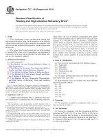
Cp = 1⁄2 (cot A/2 × tan B/2),
A = included longitudinal edge angle (see Fig. 1), and
B = included transverse edge angle (see Fig. 1).
1.1 This test method covers the determination of the Knoop
indentation hardness of glass and the verification of Knoop
indentation hardness testing machines using standard glasses.
1.2 This standard does not purport to address all of the
safety concerns, if any, associated with its use. It is the
responsibility of the user of this standard to establish appropriate safety and health practices and determine the applicability of regulatory limitations prior to use.
3.1.3 Knoop indentation hardness tests in glass are made at
a test load of 100 gf (0.1 kgf).
3.1.4 The rate of indenter motion prior to contact with the
specimen shall be 0.20 6 0.05 mm/min. This low rate of load
application tends to alleviate the effect of the magnitude of the
load on Knoop hardness number.
3.1.5 The indenter should remain in contact with the specimen between 20 and 30 s. Most of the calibrated machines that
are used for making Knoop hardness tests are dash-pot
controlled and this dwell time is consistent with the adjustment
of the dash-pot to meet the loading rate standard.
3.1.6 Table 1 gives the Knoop hardness of several glasses as
a function of load when the loading rate and dwell time are
held at the values recommended above.
3.1.7 Knoop indentation hardness test—an indentation hardness test using a calibrated machine to force a pointed,
rhombic-base, pyramidal diamond indenter having specified
face angles, under a predetermined load, into the surface of the
material under test and to measure the long diagonal of the
resulting impression after removal of the load.
2. Referenced Documents
2.1 ASTM Standards:2
E4 Practices for Force Verification of Testing Machines
E384 Test Method for Knoop and Vickers Hardness of
Materials
3. Terminology
3.1 Definitions of Terms Specific to This Standard:
3.1.1 Knoop hardness number (KHN)—a number obtained
by dividing the applied load in kilograms-force by the projected area of the indentation in square millimetres, computed
from the measured long diagonal of the indentation and the
included edge angles of the diamond. It is assumed that the
indentation is an imprint of the undeformed indenter.
3.1.2 The Knoop hardness number (KHN) is computed as
follows:
KHN 5 ~ P/A p ! 5 ~ P/d 2 C p !
NOTE 1—A general description of the Knoop indentation hardness test
is given in Test Method E384. The present method differs from this
description only in areas required by the special nature of glasses.
4. Significance and Use
(1)
4.1 The Knoop indentation hardness is one of many properties that is used to characterize glasses. Attempts have been
made to relate Knoop indentation hardness to tensile strength,
grinding speeds, and other hardness scales, but no generally
accepted methods are available. Such conversions are limited
in scope and should be used with caution, except for special
cases where a reliable basis for the conversion has been
obtained by comparison tests.
P = load, kgf,
Ap = projected area of the indentation, mm2,
d = length of the long diagonal of the indentation, mm,
1
This test method is under the jurisdiction of ASTM Committee C14 on Glass
and Glass Products and is the direct responsibility of Subcommittee C14.04 on
Physical and Mechanical Properties.
Current edition approved Oct. 1, 2013. Published October 2013. Originally
approved in 1972. Last previous edition approved in 2008 as C730 – 98 (2008).
DOI: 10.1520/C0730-98R13.
2
For referenced ASTM standards, visit the ASTM website, www.astm.org, or
contact ASTM Customer Service at For Annual Book of ASTM
Standards volume information, refer to the standard’s Document Summary page on
the ASTM website.
5. Apparatus
5.1 Testing Machines:
5.1.1 There are two general types of machines available for
making this test. One type is a self-contained unit built for this
Copyright © ASTM International, 100 Barr Harbor Drive, PO Box C700, West Conshohocken, PA 19428-2959. United States
1
C730 − 98 (2013)
FIG. 1 Knoop Indenter Showing Maximum Usable Dimension
TABLE 1 Knoop Hardness of NIST Standard and Other GlassesA
NIST 715
GE
Fused
Quartz
Laboratory
NIST 710
NIST 711
A
C
D
E
F
G
Avg
Departure, max,
%
Range, max, %
486
594
479
521
498
411
450
426
415
414
589
614
505
608
568
516
15
423
6
22
9
,B
NIST 710
NIST 711
394
415
380
392
403
575
559
541
620
643
497
537
478
497
484
538
574
567
501
586
577
567.5
11
609.5
11
499
8
397
5
563.5
5
556
10
18
17
12
9
7
15
25-gf Load
GE Fused Quartz
50-gf Load
100-gf Load
A
C
D
E
F
G
Avg
Departure, max,
%
Range, max, %
NIST 715
200-gf Load
475
478
452
490
467
481
474
5
387
387
368
396
381
388
384.5
4
558
554
521
544
538
550
544
4
554
593
473
530
524
558
539
12
468
468
433
488
457
380
371
360
372
367
550
544
529
546
524
523
530
474
510
502
463
6
370
3
539
3
508
7
8
7
7
22
12
5
5
11
A
NIST 710—NIST standard soda-lime-silica glass (no longer available; NIST 710a may be substituted), NIST 711—NIST standard lead-silica glass. NIST 715—NIST
standard alkali-free aluminosilicate glass.
These data were obtained from ASTM round-robin testing.
B
purpose, and the other type is an accessory available to existing
microscopes. Usually, this second type is fitted on an invertedstage microscope. Good descriptions of the various machines
are available.3,4
5.1.2 Design of the machine should be such that the loading
rate, dwell time, and applied load can be standardized within
the limits set forth in 3.1.3 – 3.1.5. It is an advantage to
eliminate the human element whenever possible by appropriate
machine design. The machine should be designed so that
3
Specifications for Knoop indenters can be found in the book Small, L.,
Hardness Theory and Practice (Part I: Practice), Service Diamond Tool Co., Ann
Arbor, MI, 1960, pp. 241–243.
4
Mott, B. W., Micro-Indentation Hardness Testing, Butterworth’s Scientific
Publications, London, 1956.
2
C730 − 98 (2013)
0.1 gf. Other methods of verifying the load application are
given in Practices E4.
vibrations induced at the beginning of a test will be damped out
by the time the indenter touches the sample.
5.1.3 The calibration of the balance beam should be checked
monthly or as needed. Indentations in standard glasses are also
used to check calibration when needed.
7.2 Verification by Standard Glasses—Table 1 gives the
Knoop hardness of several standard glasses. Knoop hardness
measurement on a piece of one of these glasses that has been
ground and polished within the last 24 h should agree with the
value in the table 65 %. Tests should be made using 100 gf.
5.2 Indenter:
5.2.1 The indenter shall meet the specifications for Knoop
indenters.4 See Test Method E384.
5.2.2 Fig. 1 shows the indenter and its maximum usable
dimensions. The diagonals have an approximate ratio of 7:1,
and the depth of the indentation is about 1⁄30 the length of the
long diagonal. A perfect Knoop indenter has the following
angles:
5.2.2.1 Included longitudinal angle 172° 30' 00".
5.2.2.2 Included transverse angle 130° 00' 00".
5.2.3 The constant Cp for a perfect indenter is 0.07028 and
the specifications require a variation of not more than 1 percent
from this value.
8. Procedure
8.1 Specimen Placement—Place the specimen on the stage
of the machine in such a way so that the specimen will not be
able to rock or shift during the measurement.
8.2 Specimen Leveling:
8.2.1 The surface of the specimen being tested must lie in a
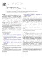
plane normal to the axis of the indenter. Fig. 2 shows an
indentation as it will appear through the microscope with five
points labeled. To level the specimen, make a test indentation
using a 100-gf load.
8.2.2 The following minimum specifications must be met:
5.3 Measuring Microscope—The measurement system shall
be so constructed that the length of the diagonals can be
determined with errors not exceeding 60.0005 mm. The
apparent length of the diagonal should be corrected for the
limit of resolution of the objective being used in the microscope (see Appendix X1).
OA 5 OB65 %
OC 5 OD65 %
8.2.3 Leveling the specimen to meet these specifications is
facilitated if one has a leveling device.
6. Test Specimen
8.3 Magnitude of Test Load—A test load of 100 gf is
specified. If cracks develop at this load, measurements within
50 or 25-gf loads may be made although the Knoop indentation
6.1 The Knoop indentation hardness test is adaptable to a
wide variety of glass specimens, ranging from tubing to
television faceplates to polished plate glass. In general, the
accuracy of the test will depend on the smoothness of the
surface and, whenever possible, ground and polished specimens should be used. The back of the specimen shall be fixed
so that the specimen cannot rock or shift during the test.
6.1.1 Thickness—As long as the specimen is over ten times
as thick as the indentation depth, this will not affect the test. In
general, if specimens are at least 0.10 mm thick, the hardness
will not be affected by variations in the thickness.
6.1.2 Surface Finish—As pointed out above, the accuracy of
the test depends on the surface finish. However, if one is
investigating a surface coating or treatment, he cannot grind
and polish the sample. Experience has shown that six indentations on a ground and polished surface of glass will reproduce within 61 %. Six indentations on an “as-received”
surface may be as bad as 610 %. Ground and polished surfaces
should be used. If this is not possible, the number of indentations should be increased.
6.1.3 Radius of Curvature—The KHN obtained will be
affected even when the curvature is only in the direction of the
short diagonal. Care should be used when relating KHN values
obtained on curved surfaces to those obtained on polished flat
surfaces.
7. Verification of Apparatus
7.1 Verification of Load—Most of the machines available
for Knoop hardness testing use a loaded beam. This beam
should be tested for zero load. An indentation should not be
visible with zero load, but the indenter should contact the
sample. A visible indentation should be obtained with a load of
FIG. 2 Sampling Leveling Measurements
3
C730 − 98 (2013)
temperature. This is because the magnification of a microscope
depends on the tube length.
9.1.2 Carefully calibrate the measuring system with a stage
micrometer or, better, with a grating.
9.1.3 If either a measuring microscope or a filar micrometer
is used, always rotate the drum in the same direction to
eliminate backlash errors.
9.1.4 Check each reading twice. They should reproduce to
60.0002 mm. One filar unit is equal to about 0.0002 mm when
a 50× objective is used in conjunction with a filar micrometer
that has a millimetre scale and a 100-division drum.
9.1.5 Use the same filters in the light system at all times.
Usually a green filter is used.
hardness does vary with load. Table 1 gives an indication of the
magnitude of this variation to be expected. In all cases, the load
actually used should be reported.
8.4 Application of Test Load:
8.4.1 Start the machine smoothly. If the machine is loaded
by an electrical system or a dash-pot lever system, it should be
mounted on shock absorbers which damp out all vibrations by
the time the indenter touches the specimen. If the specimen is
hand-loaded, take extreme care to see that the loading rate
never goes higher than 0.25 mm/min.
8.4.2 After the indenter has been in contact with the
specimen for the required dwell time, carefully raise it off the
sample to avoid a vibration impact at this time.
8.5 Spacing of Indentations—Allow a distance of at least
three times the short diagonal between indentations.
10. Conversion of Diagonal Measurement to KHN
10.1 Convert the diagonal measurement KHN by using
either Eq X1.2 or Eq X1.3 of Appendix X1, or prepare tables
using these equations.
8.6 Number of Indentations—The number of indentations
will vary with the type of specimen. For example, if one is
investigating the hardness gradient in an ion-exchanged
sample, he will make a series on indentations and plot the KHN
as a function of distance. In the usual test, one has a piece of
glass that is fairly homogeneous and he is trying to obtain a
mean KHN for that specimen. In this case, it is recommended
that at least ten indentations be made and that both the mean
KHN and the standard deviation be reported. The standard
deviation is:
s5
¯ 2 KHN ! / ~ n2 !
=Σ ~ KHN
2
n
11. Report
11.1 Report the following:
11.1.1 Mean KHN,
11.1.2 Test load,
11.1.3 Surface conditions and surface preparation,
11.1.4 Thermal history of the sample,
11.1.5 Number of indentations, and
11.1.6 Standard deviation.
(2)
12. Precision and Bias
s
¯
KHN
KHNn
n
=
=
=
=
12.1 Precision—One operator on one testing machine is
generally 62 % (coefficient of variation) for 100 to 200-gm
levels. Lower load statistics increase the coefficient of variation
to 66 %.
standard deviation of a single observation,
mean KHN,
KHN obtained from nth indentation, and
number of indentations.
12.2 Bias—The scientific community has avoided norms for
this property. The data in Table 1 may be referenced for
comparison. These data lend some measure for bias
determination, but by no means are intended for absolute
reference.
9. Measurement of Indentation
9.1 The accuracy of the test method depends to a very large
extent on this measurement, as follows:
9.1.1 If the measuring system contains a light source, take
care to use the system only after it has reached equilibrium
13. Keywords
13.1 glass; hardness; indentation; Knoop
4
C730 − 98 (2013)
APPENDIXES
(Nonmandatory Information)
X1. CALCULATION OF TABLES TO CONVERT DIAGONAL LENGTHS TO KNOOP HARDNESS NUMBERS
X1.2 Combining Eq X1.1 and Eq X1.2:
X1.1 Equation one given in 3.1.2 was:
KHN 5
P
d 2C p
(X1.1)
KHN 5
where d is the length of the long diagonal of the indentation,
in mm. However, in the microscope only part of this diagonal is seen due to the finite resolving power of the light microscope.5
d 5 d o1
7λ
2NA
S
P
7λ
d o1
2NA
D
(X1.3)
2
Cp
X1.3 It is often convenient to include the conversion from
filar units to millimetres in the table. In this case, the equation
becomes:
(X1.2)
KHN 5
where:
= apparent length of the long diagonal as measured
do
with light microscope, mm,
λ
= wavelength of light, mm, and
NA = numerical aperture of objective used in microscope.
S
P
7λ
LK1
2NA
D
(X1.4)
2
Cp
where:
L = apparent length of the long diagonal in filar units as
measured with the light microscope, and
K = calibration constant, which tells what fraction of a
millimetre is represented by a filar unit.
5
The round robin was conducted by Subcommittee C14.04 on Physical and
Mechanical Properties.
X2. ASTM ROUND ROBIN ON STANDARD GLASSES
X2.1 The data presented in Table 1 are the results of an
ASTM round robin on NIST standard and other glasses using
the procedure given in this test method.5
X2.2 The 100 gf numbers can be used for verification in
accordance with 7.2.
ASTM International takes no position respecting the validity of any patent rights asserted in connection with any item mentioned
in this standard. Users of this standard are expressly advised that determination of the validity of any such patent rights, and the risk
of infringement of such rights, are entirely their own responsibility.
This standard is subject to revision at any time by the responsible technical committee and must be reviewed every five years and
if not revised, either reapproved or withdrawn. Your comments are invited either for revision of this standard or for additional standards
and should be addressed to ASTM International Headquarters. Your comments will receive careful consideration at a meeting of the
responsible technical committee, which you may attend. If you feel that your comments have not received a fair hearing you should
make your views known to the ASTM Committee on Standards, at the address shown below.
This standard is copyrighted by ASTM International, 100 Barr Harbor Drive, PO Box C700, West Conshohocken, PA 19428-2959,
United States. Individual reprints (single or multiple copies) of this standard may be obtained by contacting ASTM at the above
address or at 610-832-9585 (phone), 610-832-9555 (fax), or (e-mail); or through the ASTM website
(www.astm.org). Permission rights to photocopy the standard may also be secured from the Copyright Clearance Center, 222
Rosewood Drive, Danvers, MA 01923, Tel: (978) 646-2600; />
5