Astm c 831 98 (2013)
Bạn đang xem bản rút gọn của tài liệu. Xem và tải ngay bản đầy đủ của tài liệu tại đây (281.04 KB, 7 trang )
Designation: C831 − 98 (Reapproved 2013)
Standard Test Methods for
Residual Carbon, Apparent Residual Carbon, and Apparent
Carbon Yield in Coked Carbon-Containing Brick and
Shapes 1
This standard is issued under the fixed designation C831; the number immediately following the designation indicates the year of
original adoption or, in the case of revision, the year of last revision. A number in parentheses indicates the year of last reapproval. A
superscript epsilon (´) indicates an editorial change since the last revision or reapproval.
1. Scope
D2906 Practice for Statements on Precision and Bias for
Textiles (Withdrawn 2008)3
E11 Specification for Woven Wire Test Sieve Cloth and Test
Sieves
1.1 These test methods cover the determination of residual
carbon content in carbon-bearing brick and shapes after a
prescribed coking treatment. They provide two procedures.
The first procedure is based on the combustion of carbon and
its measurement as carbon dioxide. However, when using the
first procedure for articles that contain silicon carbide or other
carbides, no distinction will be made between carbon present in
the form of a carbide and carbon present as elemental carbon.
The second procedure provides a method for calculating
apparent residual carbon (on the basis of weight loss after
igniting the coked specimens), apparent carbonaceous material
content, and apparent carbon yield. If the second procedure is
used for brick or shapes that contain metallic additives or
carbides, it must be recognized that there will be a weight gain
associated with the oxidation of the metals, or carbides, or
both. Such a weight gain can change the results substantially
and this must be kept in mind when interpreting the data.
3. Significance and Use
3.1 These test methods are designed for use with carboncontaining products. The residual carbon content of a coked
carbon containing brick or shape is an indication of how much
carbon may be available, in service, to resist slag attack on, or
oxidation loss of, that body. Apparent carbon yield gives an
estimate of the relative efficiency of the total carbonaceous
matter to be retained as residual carbon.
3.2 Residual carbon has a direct bearing on several properties of a pitch or resin containing refractory such as ignited
porosity, density, strength, and thermal conductivity.
3.3 These test methods are suitable for product
development, manufacturing control and specification acceptance.
1.2 The values stated in inch-pound units are to be regarded
as the standard. The values given in parentheses are for
information only.
1.3 This standard does not purport to address all of the
safety concerns, if any, associated with its use. It is the
responsibility of the user of this standard to establish appropriate safety and health practices and determine the applicability of regulatory limitations prior to use.
3.4 These test methods are very sensitive to specimen size,
coking rates, etc.; therefore, strict compliance with these test
methods is critical.
3.5 Appreciable amounts of reducible components, such as
Fe2O3, will have a noticeable effect on the results. Thus, values
obtained by these test methods will be different when brick
removed from service is tested. This must be kept in mind
when attempting to use these test methods in an absolute sense.
2. Referenced Documents
3.6 Oxidizable components such as metals and carbides can
have a noticeable effect on the results. This must be kept in
mind when using the second procedure, which is based on
measuring weight loss after igniting the coked specimens.
2.1 ASTM Standards:2
C571 Methods for Chemical Analysis of Carbon and
Carbon-Ceramic Refractories (Withdrawn 1995)3
3.7 Testing of brick or shapes that contain magnesium metal
presents special problems since this metal is highly volatile and
substantial amounts of the magnesium can be lost from the
sample during the coking procedure. This must be kept in mind
when interpreting the results of testing of brick that contain
1
These test methods are under the jurisdiction of ASTM Committee C08 on
Refractories and are the direct responsibility of Subcommittee C08.04 on Chemical
Behaviors.
Current edition approved April 1, 2013. Published August 2013. Originally
approved in 1976. Last previous edition approved in 2008 as C831 – 98 (2008).
DOI: 10.1520/C0831-98R13.
2
For referenced ASTM standards, visit the ASTM website, www.astm.org, or
contact ASTM Customer Service at For Annual Book of ASTM
Standards volume information, refer to the standard’s Document Summary page on
the ASTM website.
3
The last approved version of this historical standard is referenced on
www.astm.org.
Copyright © ASTM International, 100 Barr Harbor Drive, PO Box C700, West Conshohocken, PA 19428-2959. United States
1
C831 − 98 (2013)
4.2.1 Laboratory Pulverizer4designed to provide a sealed,
dustproof grinding chamber, and having a capacity of at least
50 g of sample.
4.2.2 Combustion-Tube Furnace capable of operating at
183°F (1000°C)
4.2.3 CO2-Absorption Train as described in Fig. 4 and in
Method
magnesium. In addition, magnesium can react readily with
atmospheric humidity. This must be kept in mind when storing
brick that contain magnesium.
4. Apparatus
4.1 For Coking:
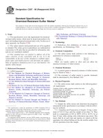
4.1.1 Gas or Electric Furnace with heating chamber capable of receiving the coking box shown in Fig. 1.
NOTE 2—Commercial automatic and semi-automatic carbon determinators may replace the apparatus described in 4.2.2 and 4.2.3.
NOTE 1—Samples should not be subjected to thermal gradients greater
than 40°F (22°C) during heatup. In electric furnaces with silicon carbide
heating elements, the length of the box should be parallel to these
elements.
4.3 The precision obtained with these instruments shall
meet the requirements specified in Section 10.
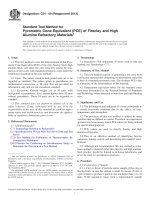
4.1.2 Inner and Outer Box, stainless steel (or equivalent
alloy), as shown in Figs. 1-3.
5. Preparation of Test Specimens
5.1 This method assumes that the number of specimens
tested will be a statistically valid sample of the entire lot of
4.2 For CO2 Absorption:
4
Typical grinders are: Blueler Mill, Applied Research Laboratories, Sunland,
CA; Laboratory Disc Mill, Angstrom, Inc., Bellville, MI; and Shatter Box, Spex
Industries, Inc., Metuchen, NJ.
FIG. 1 Outer Coking Box (Dimensions are in Inches)
2
C831 − 98 (2013)
FIG. 2 Inner Coking Box
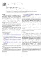
size of each slice shall be 1 by 3 by 6 in. (25 by 76 by 152 mm).
The two 1 by 3-in. faces and the two 1 by 6-in. faces must be
original surfaces.
brick or shapes being evaluated. The exact number is usually
arrived at by mutual agreement between parties concerned.
5.2 Although sample brick from either the 41⁄2-in. (114-mm)
or the 6-in. (152-mm) series may be tested, it is preferable to
use the larger size for the test. Cut slices 1 6 1⁄32 in. (25 6 0.8
mm) in thickness perpendicular to the length at the mid-section
of each sample brick or shape. As shown in Fig. 5, the nominal
5.3 Test specimens may be cut wet or dry except for
products capable of hydration, such as dolomite brick, which
must be cut dry and stored in a dry container prior to coking.
3
C831 − 98 (2013)
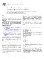
FIG. 3 Coking Box Arrangement
FIG. 4 CO2-Absorption Train
5.4 Specimens that are cut wet must be dried immediately
with a paper or cloth towel and flash dried. For pitchimpregnated samples, flash drying should be done at a sufficiently low temperature to avoid “weeping” of pitch from the
pores of the brick. Drying can usually be done on a forced-air
dryer at 220°F (105°C) by limiting exposure to 5 to 10 min.
Repeat if necessary. These drying procedures are especially
important for metal-containing brick because hydration of the
4
C831 − 98 (2013)
FIG. 5 Location of Test Specimen
6.6 Heat the furnace so that the thermocouple within the box
registers 250°F (120°C) after the first hour, then heat the
furnace so that the box is heated at a rate of 400 6 20°F (2206
11°C)/h to 1800 6 20°F (980 6 11°C).
metals can occur. Specimens containing a coating of pitch on
uncut surfaces, as is typical of an impregnation process, must
be scraped clean prior to drying.
5.5 Weigh all specimens after drying to constant weight
(60.2g), recording weight to the nearest 0.1 g. This weight is
“as-received weight, A,” (This step may be omitted if residual
carbon is to be determined by CO2 absorption, as indicated in
1.1.)
6.7 Hold the temperature for 3 6 1⁄2 h, starting from the time
1780°F (970°C) is reached in the inner box.
6.8 After completing the hold period, shut off the furnace
and allow the coking box to cool naturally within the furnace.
6. Procedure for Coking
6.9 Remove the samples from the coking box after the box
has cooled sufficiently to handle. After removing specimens
from the inner box, clean by brushing carefully with a nylon or
natural bristle brush to remove clinging particles. Then proceed
to either of the two alternatives for analyzing the specimens.
6.1 Place the test specimens randomly into the inner box,
Fig. 2
NOTE 3—Burned pitch-impregnated magnesite brick should not be
coked with tempered, tar-bonded, or dolomite brick because of carbon
pickup by the impregnated samples and disruption of the bottom of
tempered samples. Pitch-bonded, pitch-bonded tempered magnesite brick
and dolomite brick may be coked in the same box or coking run.
NOTE 4—The number of samples coked per run should be constant
within a laboratory. Dummy uncoked samples consistent with Note 3 may
be used to fill any empty positions in the inner box.
NOTE 6—After each run, clean the muffle and the bottom carbon plate
of any adhering coke breeze.
6.10 Samples that contain dolomite or aluminum metal
should be stored in a sealed container containing dessicant in
the time interval between coking and measurement of carbon
content. This is to prevent hydration of dolomite or aluminum
carbide. The aluminum carbide is formed by reaction between
aluminum and carbon in the shape during the coking operation.
Aluminum carbide can react with a water source such as
atmospheric humidity to form methane. Care should be taken
since methane can be an explosion hazard.
6.2 Place the inner box into the center of the outer box (Fig.
3), on the bottom of which has first been placed a 1⁄2-in.
(13-mm) slab of carbon, covered with a thin layer of dust-free
metallurgical-grade coke breeze (No. 14 (1.40–mm) sieve size)
(Note 5). To ensure that the coke breeze is free of moisture
which could oxidize carbon during cooking, dry the coke at
400°F (205°C) for 24 h, and keep in a closed container at room
temperature until needed.
CO2 ABSORPTION (FIRST ALTERNATIVE
PROCEDURE)
NOTE 5—Detailed requirements for sieves are given in Specification
E11.
7. Preparation of Sample
6.3 Place the thermocouple well into the center of the inner
box and put the lid on the inner box. The thermocouple well
must be long enough to extend above the cover of the outer
box.
7.1 A sample consists of a single slice or multiple specimens
of brick prepared as described in Sections 5 and 6.
7.2 Crush the sample in a laboratory jaw crusher, or other
impact-type crusher, to pass a No. 4 (4.75-mm) sieve (Note 5).
Thoroughly mix the crushed sample and reduce to approximately 50 g by quartering or riffling.
6.4 Cover the inner box with metallurgical-grade coke
breeze retained on a No. 14 sieve and place a loose-fitting lid
over the coke breeze (see Fig. 3). Pack the coke breeze between
the edges of the lid and box.
7.3 Place the sample in the laboratory pulverizer and grind
to 100 % passing a No. 100 (150 µm) sieve. This takes
approximately 90 to 100 s. Promptly transfer the ground
sample to a suitable airtight container.
6.5 Place the coking-box assembly (Fig. 3) into the furnace,
and insert a calibrated thermocouple into the thermocouple
well.
5
C831 − 98 (2013)
10.2 On the basis of the components of variance in 10.1, we
would expect two averages of an equal number of specimens
tested by this test method to be considered different at the 95 %
probability level if their difference exceeds the values below
(for t = 1.96) (assume that two replicates are always used per
test method:
NOTE 7—Extreme care must be taken during the entire sample
preparation to avoid loss of carbon by segregation or dusting. About 60 %
of the variance in this procedure is in this step.
8. Procedure
8.1 With the furnace at operating temperature, pass oxygen
through the absorption train until the CO2-absorption bulb
attains constant weight (usually 15 to 30 min). Adjust the
oxygen pressure and flow rate to provide 120 to 150 bubbles
per minute through the bubbling tower. Close the stopcock,
remove the absorption bulb from the train, cool to room
temperature, and weigh to the nearest 0.1 mg.
Number of Samples
in Each Average
1
6
12
IGNITION LOSS (SECOND ALTERNATIVE
PROCEDURE)
11. Procedure
11.1 Weigh all specimens to the nearest 0.1 g and record as
“coked weight, B.”
8.3 Remove the absorption bulb from the train, close the
stopcock, cool to room temperature, and reweigh. The increase
in weight is the CO2 won from the sample by combustion of
the carbon.
11.2 Place specimens on a layer of magnesia grain in a kiln
or furnace.
11.3 Heat specimens in an air atmosphere (preferably circulating) at 500 to 700°F (280 to 380°C)/h to a temperature
between 1800 and 2200°F (980 to 1205°C). For alumina-silica
refractories, ignition temperature should be limited to 1800°F.
9. Calculation and Report
9.1 Calculate the percentage of residual carbon in the
sample as follows:
wt of CO2 3 0.2729 3 100
wt of sample
11.4 Hold the selected temperature for a minimum of 8 h
(depending on the temperature in 11.3), or until a constant
weight (60.2 g) is obtained (Note 9).
(1)
NOTE 9—Samples containing 20 % or more carbon or samples
containing oxidation inhibitors may require longer hold times of up to 40
h at a temperature of 2000°F (1095°C).
9.2 Run the determinations in duplicate. Results shall not
vary by more than 60.05 % stated in terms of the whole
sample as 100 %. If satisfactory checks are not obtained, repeat
the analysis in duplicate. Report at least two individual
analyses per slice.
11.5 At the end of the soak, shut off the furnace and cool the
specimens naturally within the furnace.
11.6 Weigh ignited specimens to the nearest 0.1 g and
record as “ignited weight, C.”
10. Precision and Bias5
10.1 An interlaboratory study was conducted in 1970 using
a nested experimental design wherein a composite of several
sizes of magnesite grain and lampblack was mixed in accurately weighed proportions, divided into four samples, and sent
to four laboratories for testing. Each laboratory split its sample
into four specimens, ground them for analysis and made two
replicate determinations on each. The components of variance
(Note 8) of the results given in terms of standard deviations
were found to be as follows:
Grand mean
Between laboratories (σL)
Between samples (σS
Between replicates (σR)
Between Two
Laboratories
0.350
0.245
0.232
10.3 These precision data may not be applicable for samples
with substantially higher carbon contents or for samples that
contain metals.
8.2 Into a previously ignited combustion boat, weigh a 0.1
to 1.0 g sample to the nearest 0.1 mg. Return the weighed CO2
absorption bulb to the train and open the stopcock. Then place
the combustion boat with sample in the combustion tube and
immediately reseal the train. Adjust the flow of oxygen as
before (8.1), heat the furnace to 1740 to 1830°F (950 to
1000°C), and maintain until the CO2 adsorption bulb attains
constant weight (usually 45 to 60 min).
Residual carbon, % 5
Between Samples
Within One Laboratory
0.274
0.116
0.085
12. Calculation and Report
12.1 The following equations apply:
Apparent residual carbon ~ RC! , % 5
B2C
3 100
B
Loss on ignition ~ LOI! , ~ % apparent pitch! 5
Apparent carbon yield ~ CY! , % 5
Carbon Content , %
4.572
± 0.0778
± 0.0987
± 0.0161
A2C
3 100
A
B2C
3 100
A2C
(2)
(3)
(4)
where:
A = as-received weight (5.5),
B = coked weight (11.1), and
C = ignited weight (11.6).
NOTE 8—A procedure for calculating precision is fully described in
Practice D2906. There is no known means for determining the bias of
these test methods.
12.2 Report the average, standard deviation, and number of
specimens tested, retaining two significant figures.
13. Precision and Bias
5
Supporting data have been filed at ASTM International Headquarters and may
be obtained by requesting Research Report RR:C08-1012. Contact ASTM Customer
Service at
13.1 Interlaboratory Test Program—A round-robin comparison among five laboratories was completed in early 1973.
6
C831 − 98 (2013)
TABLE 1 Precision Statistics
Precision Data
Grand
Product
Average, x
Apparent Residual Carbon, %
95 % MgO Tl
2.41
20 % MgO
17.79
20 % MgO-C w/metal
17.47
Standard
Error, Sr
Deviation
Between, SR
95 %
Repeatability
Interval, r
95 %
Relative
Coefficient of Variation
Reproducibility Precision Within Lab, Between Lab,
Interval, R Average, x
Vr
VR
Relative
Relative
Repeatability, Reproducibility,
%r
%R
0.06
0.56
0.23
0.07
0.56
0.23
0.17
1.56
0.64
0.19
1.56
0.64
2.42
17.79
17.47
2.49
3.12
1.31
2.82
2.69
1.24
6.97
8.75
3.65
7.89
7.54
3.48
Loss On Ignition, %
95 % MgO Tl
20 % MgO
20 % MgO-C w/metal
5.30
18.75
18.32
0.09
0.60
0.35
0.07
0.81
0.43
0.24
1.69
0.98
0.20
2.28
1.21
5.30
18.75
18.32
1.60
3.21
1.91
1.32
4.34
2.36
4.49
9.00
5.33
3.70
12.20
6.61
Apparent Carbon
Yield, %
95 % MgO Tl
20 % MgO
20 % MgO-C w/metal
44.30
91.76
93.36
1.30
0.17
0.29
1.50
0.41
1.39
3.64
0.48
0.81
4.20
1.13
3.88
44.30
91.76
93.36
2.94
0.19
0.31
3.39
0.44
1.49
8.22
0.53
0.87
9.43
1.24
4.16
13.2.2 Reproducibility—The maximum permissible difference due to test error between two test results obtained by two
operators in different laboratories on the same material using
the same test equipment is given by the reproducibility interval
and the relative reproducibility interval (coefficient of variation). The 95 % reproducibility intervals are given in Table 1.
Two test results which do not differ by more than the
reproducibility interval will be considered to be from the same
population and, conversely, two test results which do differ by
more than the reproducibility interval will be considered to be
from different populations.
Each laboratory received two adjacent specimens from each of
twelve pitch-impregnated, 95 % MgO class, 3 by 6-in. (76 by
152-mm) series brick of one brand. A second round-robin
comparison was run in 1994 among three laboratories.5 Each
laboratory received five specimens each of a 20 % carbon
MgO-carbon brick with a metal addition and without a metal
addition.
13.2 Precision:
13.2.1 Repeatability—The maximum permissible difference
due to test error between two test results obtained by one
operator on the same material using the same test equipment is
given by the repeatability interval and the relative repeatability
interval (coefficient of variation). The 95 % repeatability
intervals are given in Table 1. Two test results which do not
differ by more than the repeatability interval will be considered
to be from the same population and, conversely, two test results
which do differ by more than the repeatability interval will be
considered to be from different populations.
13.3 Bias—No justifiable statement on bias is possible since
the true property values cannot be established by an accepted
reference material.
14. Keywords
14.1 carbon yield; coking; loss of ignition; refractories;
residual carbon
ASTM International takes no position respecting the validity of any patent rights asserted in connection with any item mentioned
in this standard. Users of this standard are expressly advised that determination of the validity of any such patent rights, and the risk
of infringement of such rights, are entirely their own responsibility.
This standard is subject to revision at any time by the responsible technical committee and must be reviewed every five years and
if not revised, either reapproved or withdrawn. Your comments are invited either for revision of this standard or for additional standards
and should be addressed to ASTM International Headquarters. Your comments will receive careful consideration at a meeting of the
responsible technical committee, which you may attend. If you feel that your comments have not received a fair hearing you should
make your views known to the ASTM Committee on Standards, at the address shown below.
This standard is copyrighted by ASTM International, 100 Barr Harbor Drive, PO Box C700, West Conshohocken, PA 19428-2959,
United States. Individual reprints (single or multiple copies) of this standard may be obtained by contacting ASTM at the above
address or at 610-832-9585 (phone), 610-832-9555 (fax), or (e-mail); or through the ASTM website
(www.astm.org). Permission rights to photocopy the standard may also be secured from the ASTM website (www.astm.org/
COPYRIGHT/).
7