Astm c 947 03 (2016)
Bạn đang xem bản rút gọn của tài liệu. Xem và tải ngay bản đầy đủ của tài liệu tại đây (121.52 KB, 3 trang )
Designation: C947 − 03 (Reapproved 2016)
Standard Test Method for
Flexural Properties of Thin-Section Glass-Fiber-Reinforced
Concrete (Using Simple Beam With Third-Point Loading)1
This standard is issued under the fixed designation C947; the number immediately following the designation indicates the year of
original adoption or, in the case of revision, the year of last revision. A number in parentheses indicates the year of last reapproval. A
superscript epsilon (´) indicates an editorial change since the last revision or reapproval.
exceed 61.0 % of the maximum force expected to be measured
shall be used. The testing machine shall be equipped with a
deflection measuring and recording device. The stiffness of the
testing machine shall be such that the total elastic deformation
of the system does not exceed 1.0 % of the total deflection of
the test specimen during the test, or appropriate corrections
shall be made. The force-indicating mechanism shall be
essentially free of inertial lag at the crosshead rate used. The
accuracy of the testing machine shall be verified in accordance
with Practices E4 and Specification D76.
1. Scope
1.1 This test method covers determination of the flexural
ultimate strength in bending and the yield strength of glassfiber reinforced concrete sections by the use of a simple beam
of 1.0 in. (25.4 mm) or less in depth using third-point loading.
1.2 The values stated in inch-pound units are to be regarded
as the standard. The values given in parentheses are for
information only.
1.3 This standard does not purport to address all of the
safety concerns, if any, associated with its use. It is the
responsibility of the user of this standard to establish appropriate safety and health practices and determine the applicability of regulatory limitations prior to use.
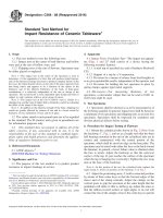
4.2 Loading Noses and Supports—The loading noses and
supports shall have cylindrical surfaces. In order to avoid
excessive indentation or failure due to stress concentration
directly under the loading noses or supports, the radius of the
noses and supports shall be at least 0.25 in. (6.35 mm). See Fig.
1 for loading configuration. The arc of the loading noses and
supports, in contact with the specimen, shall be sufficiently
large to prevent contact of the specimen with the sides of the
noses. Neoprene pads, approximately 1⁄16 in. (1.6 mm) thick,
may be placed between the loading noses and the test specimen
for uniform load distribution across the width of the specimen.
However, neoprene pads should not be used if deflection
measurements are to be made, as the compression of the
neoprene will distort the measurements.
2. Referenced Documents
2.1 ASTM Standards:2
C1228 Practice for Preparing Coupons for Flexural and
Washout Tests on Glass Fiber Reinforced Concrete
D76 Specification for Tensile Testing Machines for Textiles
E4 Practices for Force Verification of Testing Machines
3. Significance and Use
3.1 Flexural properties determined by this test method are
useful for quality control of glass-fiber reinforced concrete
products, ascertaining compliance with the governing
specifications, research and development, and generating data
for use in product design.
4.3 Loading Head and Support Apparatus—Loading noses,
supports, and their respective holding devices shall be designed
to allow rotation to occur about axes that lie in horizontal
planes of the loading apparatus as shown in Fig. 1. This
configuration of loading head and support apparatus will
ensure that forces applied to the specimen will be initially
perpendicular to the surfaces of the specimen and applied
without eccentricity.
4. Apparatus
4.1 Testing Machine—A properly calibrated testing machine
that can be operated at constant rates of crosshead motion and
in which the error in the force measuring system shall not
4.4 Specimen Depth and Width Measuring Device—A caliper or micrometer or other suitable device that is able to
measure sample depth accurate to 0.005 in. (0.13 mm) and
width accurate to 0.01 in. (0.25 mm).
1
This test method is under the jurisdiction of ASTM Committee C27 on Precast
Concrete Products and is the direct responsibility of Subcommittee C27.40 on Glass
Fiber Reinforced Concrete.
Current edition approved April 1, 2016. Published May 2016. Originally
approved in 1981. Last previous edition approved in 2009 as C947 – 03(2009). DOI:
10.1520/C0947-03R16.
2
For referenced ASTM standards, visit the ASTM website, www.astm.org, or
contact ASTM Customer Service at For Annual Book of ASTM
Standards volume information, refer to the standard’s Document Summary page on
the ASTM website.
5. Sampling
5.1 Test boards shall be manufactured in accordance with
governing specifications.
Copyright © ASTM International, 100 Barr Harbor Drive, PO Box C700, West Conshohocken, PA 19428-2959. United States
1
C947 − 03 (2016)
8.4 Center the specimen on the supports with equal lengths
of specimen projecting outside of the supports with the long
axis of the specimen perpendicular to the loading noses and
supports.
8.5 Test three specimens with the mold face in tension and
three specimens with the opposite face (or trowelled face) in
tension.
8.6 Set the crosshead speed of the testing machine at 0.05 to
0.20 in./min (1.27 to 5.1 mm/min). Set the chart speed to 75 6
25 times the crosshead speed being used. Set the initial load
measuring range such that the flexural yield strength (Fy) load
occurs at not less than 30 % of full scale. Apply force at a
constant crosshead speed to specimen failure. Examine the
failure location of the specimen. If failure occurs outside the
minor span, discard the specimen and specimen test data.
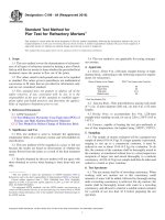
NOTE 2—The chart speed may be reduced or stopped after the
force-deflection curve reaches its point of deviation from linearity (Py in
Fig. 2) to conserve chart paper.
8.7 Record the maximum force attained (Pu) and the force
where the force-deflection curve deviates from linearity (Py).
Also the deflections should be measured at the point where the
force-deflection curve deviates from linearity (Yy) and at failure
(Yu). See Fig. 2 for a typical force-deflection chart recording.
FIG. 1 Loading Configuration for Flexural Testing
6. Test Specimen
8.8 Determine and record the average of three specimen
depth measurements to the nearest 0.005 in. (0.125 mm) at or
near the fracture location. Determine the specimen width to the
nearest 0.01 in. (0.25 mm) at or near the failure location. Use
a measuring device as described in 4.4.
6.1 Six test specimens shall be prepared in accordance with
Practice C1228.
6.2 The test specimen shall have a ratio of the specimen
major span length to the specimen depth between 16 to 1 and
30 to 1. The total specimen length shall be a minimum of 1 in.
(25 mm) longer than the specimen’s major span. Nominal
specimen width shall be 2 in. (50 mm).
NOTE 3—Observe caution to avoid measurements at locations that have
been expanded at or near the fracture.
9. Calculations
7. Conditioning
9.1 Calculate flexural yield strength (Fy) as follows:
7.1 The sample or specimens shall be transported to the
testing laboratory packaged so that no damage will take place.
F y 5 P y L/bd 2
(1)
where:
Fy = flexural yield strength psi (or MPa),
Py = force at the point on the force-deflection curve where
the curve deviates from linearity, lbf (or N),
L = major support span, in. (or mm),
b = width of specimen, in. (or mm), and
d = depth of specimen, in. (or mm).
7.2 Condition the samples or specimens in water at 73 6
5°F (23 6 3°C) for a period of minimum 24 h and maximum
72 h to ensure complete saturation and test immediately upon
removal. Remove specimens from water bath individually and
test. Do not allow specimen surfaces to dry out either prior to
or during the test. Specimen surfaces may be sprayed with
water during testing if indications of surface drying are present.
7.3 Samples or specimens shall be tested in a temperature
controlled environment at 73 6 5°F (23 6 3°C).
8. Procedure
8.1 Set the major span of the test apparatus to correspond
with 6.2.
8.2 Set the minor span to correspond with one third of the
major span.
8.3 Align the loading noses and supports so that the axes of
the cylindrical surfaces are parallel.
NOTE 1—The parallelism of the loading noses and supports may be
checked by means of a plate containing parallel grooves into which the
loading noses and supports will fit when properly aligned.
FIG. 2 Force Deflection Chart
2
C947 − 03 (2016)
10.1.3 Sample conditioning,
10.1.4 Date of testing,
10.1.5 Crosshead speed,
10.1.6 Chart speed,
10.1.7 Major span,
10.1.8 Specimen depth to nearest 0.005 in. (0.127 mm) and
width to nearest 0.01 in. (0.254 mm), and
10.1.9 Deflections at the point where the force-deflection
curve deviates from linearity and at failure.
10.1.10 Test Results:
10.1.10.1 Flexural yield strength to the nearest 5 psi (0.03
MPa), and
10.1.10.2 Flexural ultimate strength to the nearest 5 psi
(0.03 MPa).
9.2 Use of testing machines with magnification factors
(ratio of chart speed to crosshead speed) of less than 50:1 may
lead to systematic errors in identifying the point at which the
force-deflection curve deviates from linearity. Such errors may
be corrected by the use of a factor determined by comparing
results from specimens from a variety of specimens yielding a
range of proportional elastic limit values tested on machines
with and without the recommended magnification factors.
9.3 Calculate the flexural ultimate strength (Fu) as follows:
F u 5 P u L/bd 2
(2)
where:
Fu = flexural ultimate strength, psi (or MPa),
Pu = maximum force achieved by the specimen, lbf (or N),
L = major support span, in. (or mm),
b = width of specimen, in. (or mm), and
d = depth of specimen, in. (or mm).
11. Precision and Bias
11.1 The precision and bias criteria are being developed
and tests are being run.
10. Report
12. Keywords
10.1 Report the following information:
10.1.1 Identification number of specimen,
10.1.2 Sample description and age,
12.1 flexural properties; GFRC; glassfiber reinforced concrete
APPENDIX
(Nonmandatory Information)
X1. MODULUS OF ELASTICITY
X1.1 In certain circumstances a value for the Modulus of
Elasticity is required. This can be calculated as follows:
E5
5P y L 3
27Y y bd3
L
b
d
(X1.1)
= major support span, in. (or mm),
= width of specimen, in. (or mm), and
= depth of specimen, in. (or mm).
NOTE X1.1—If a deflectometer is used at the center of the major span
to measure specimen deflection in order to minimize the effects of
machine and fixture stiffness, the flexural modulus of elasticity is then
calculated using the following equation:
where:
E = initial flexural modulus of elasticity, psi (Mpa),
Yy = deflection at the point where the load-deflection curve
deviates from linearity,
Py = force at the point on the force-deflection curve where
the curve deviates from linearity, lbf (or N),
E5
23P y L 3
108Y y bd3
ASTM International takes no position respecting the validity of any patent rights asserted in connection with any item mentioned
in this standard. Users of this standard are expressly advised that determination of the validity of any such patent rights, and the risk
of infringement of such rights, are entirely their own responsibility.
This standard is subject to revision at any time by the responsible technical committee and must be reviewed every five years and
if not revised, either reapproved or withdrawn. Your comments are invited either for revision of this standard or for additional standards
and should be addressed to ASTM International Headquarters. Your comments will receive careful consideration at a meeting of the
responsible technical committee, which you may attend. If you feel that your comments have not received a fair hearing you should
make your views known to the ASTM Committee on Standards, at the address shown below.
This standard is copyrighted by ASTM International, 100 Barr Harbor Drive, PO Box C700, West Conshohocken, PA 19428-2959,
United States. Individual reprints (single or multiple copies) of this standard may be obtained by contacting ASTM at the above
address or at 610-832-9585 (phone), 610-832-9555 (fax), or (e-mail); or through the ASTM website
(www.astm.org). Permission rights to photocopy the standard may also be secured from the Copyright Clearance Center, 222
Rosewood Drive, Danvers, MA 01923, Tel: (978) 646-2600; />
3
(X1.2)