Astm d 189 06 (2014)
Bạn đang xem bản rút gọn của tài liệu. Xem và tải ngay bản đầy đủ của tài liệu tại đây (270.38 KB, 7 trang )
Designation: D189 − 06 (Reapproved 2014)
British Standard 4380
Standard Test Method for
Conradson Carbon Residue of Petroleum Products1
This standard is issued under the fixed designation D189; the number immediately following the designation indicates the year of
original adoption or, in the case of revision, the year of last revision. A number in parentheses indicates the year of last reapproval. A
superscript epsilon (´) indicates an editorial change since the last revision or reapproval.
This standard has been approved for use by agencies of the U.S. Department of Defense.
1. Scope
1.2 The values stated in SI units are to be regarded as
standard. No other units of measurement are included in this
standard.
1.1 This test method covers the determination of the amount
of carbon residue (Note 1) left after evaporation and pyrolysis
of an oil, and is intended to provide some indication of relative
coke-forming propensities. This test method is generally applicable to relatively nonvolatile petroleum products which
partially decompose on distillation at atmospheric pressure.
Petroleum products containing ash-forming constituents as
determined by Test Method D482 or IP Method 4 will have an
erroneously high carbon residue, depending upon the amount
of ash formed (Note 2 and Note 4).
1.3 WARNING—Mercury has been designated by many
regulatory agencies as a hazardous material that can cause
central nervous system, kidney and liver damage. Mercury, or
its vapor, may be hazardous to health and corrosive to
materials. Caution should be taken when handling mercury and
mercury containing products. See the applicable product Material Safety Data Sheet (MSDS) for details and EPA’s
website— additional information. Users should be aware that selling mercury
and/or mercury containing products into your state or country
may be prohibited by law.
1.4 This standard does not purport to address all of the
safety concerns, if any, associated with its use. It is the
responsibility of the user of this standard to establish appropriate safety and health practices and determine the applicability of regulatory limitations prior to use.
NOTE 1—The term carbon residue is used throughout this test method
to designate the carbonaceous residue formed after evaporation and
pyrolysis of a petroleum product under the conditions specified in this test
method. The residue is not composed entirely of carbon, but is a coke
which can be further changed by pyrolysis. The term carbon residue is
continued in this test method only in deference to its wide common usage.
NOTE 2—Values obtained by this test method are not numerically the
same as those obtained by Test Method D524. Approximate correlations
have been derived (see Fig. X1.1), but need not apply to all materials
which can be tested because the carbon residue test is applied to a wide
variety of petroleum products.
NOTE 3—The test results are equivalent to Test Method D4530, (see
Fig. X1.2).
NOTE 4—In diesel fuel, the presence of alkyl nitrates such as amyl
nitrate, hexyl nitrate, or octyl nitrate causes a higher residue value than
observed in untreated fuel, which can lead to erroneous conclusions as to
the coke forming propensity of the fuel. The presence of alkyl nitrate in
the fuel can be detected by Test Method D4046.
2. Referenced Documents
2.1 ASTM Standards:2
D482 Test Method for Ash from Petroleum Products
D524 Test Method for Ramsbottom Carbon Residue of
Petroleum Products
D4046 Test Method for Alkyl Nitrate in Diesel Fuels by
Spectrophotometry
D4057 Practice for Manual Sampling of Petroleum and
Petroleum Products
D4175 Terminology Relating to Petroleum, Petroleum
Products, and Lubricants
D4177 Practice for Automatic Sampling of Petroleum and
Petroleum Products
D4530 Test Method for Determination of Carbon Residue
(Micro Method)
E1 Specification for ASTM Liquid-in-Glass Thermometers
E133 Specification for Distillation Equipment
1
This test method is under the jurisdiction of ASTM Committee D02 on
Petroleum Products, Liquid Fuels, and Lubricants and is the direct responsibility of
Subcommittee D02.06 on Analysis of Lubricants.
Current edition approved Oct. 1, 2014. Published November 2014. Originally
approved in 1924. Last previous edition approved in 2010 as D189 – 06 (2010)ε1.
DOI: 10.1520/D0189-06R14.
In the IP, this test method is under the jurisdiction of the Standardization
Committee and is issued under the fixed designation IP 13. The final number
indicates the year of last revision. This test method was adopted as a joint ASTM–IP
standard in 1964.
This procedure is a modification of the original Conradson method and apparatus
for Carbon Test and Ash Residue in Petroleum Lubricating Oils. See Proceedings,
Eighth International Congress of Applied Chemistry, New York, Vol 1, p. 131,
September 1912; also Journal of Industrial and Engineering Chemistry, IECHA,
Vol 4, No. 11, December 1912.
In 1965, a new Fig. 2 on reproducibility and repeatability combining ASTM and
IP precision data replaced old Fig. 2 and Note 4.
2
For referenced ASTM standards, visit the ASTM website, www.astm.org, or
contact ASTM Customer Service at For Annual Book of ASTM
Standards volume information, refer to the standard’s Document Summary page on
the ASTM website.
Copyright © ASTM International, 100 Barr Harbor Drive, PO Box C700, West Conshohocken, PA 19428-2959. United States
1
D189 − 06 (2014)
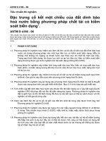
FIG. 1 Apparatus for Determining Conradson Carbon Residue
deposits in vaporizing pot-type and sleeve-type burners.
Similarly, provided alkyl nitrates are absent (or if present,
provided the test is performed on the base fuel without
additive) the carbon residue of diesel fuel correlates approximately with combustion chamber deposits.
3. Terminology
3.1 Definitions:
3.1.1 carbon residue, n—the residue formed by evaporation
and thermal degradation of a carbon containing material.
3.1.1.1 Discussion—The residue is not composed entirely of
carbon but is a coke that can be further changed by carbon
pyrolysis. The term carbon residue is retained in deference to
its wide common usage. D4175
5.2 The carbon residue value of motor oil, while at one time
regarded as indicative of the amount of carbonaceous deposits
a motor oil would form in the combustion chamber of an
engine, is now considered to be of doubtful significance due to
the presence of additives in many oils. For example, an
ash-forming detergent additive may increase the carbon residue
value of an oil yet will generally reduce its tendency to form
deposits.
4. Summary of Test Method
4.1 A weighed quantity of sample is placed in a crucible and
subjected to destructive distillation. The residue undergoes
cracking and coking reactions during a fixed period of severe
heating. At the end of the specified heating period, the test
crucible containing the carbonaceous residue is cooled in a
desiccator and weighed. The residue remaining is calculated as
a percentage of the original sample, and reported as Conradson
carbon residue.
5.3 The carbon residue value of gas oil is useful as a guide
in the manufacture of gas from gas oil, while carbon residue
values of crude oil residuums, cylinder and bright stocks, are
useful in the manufacture of lubricants.
6. Apparatus (see Fig. 1)
5. Significance and Use
6.1 Porcelain Crucible, wide form, glazed throughout, or a
silica crucible; 29- to 31-mL capacity, 46 to 49 mm in rim
diameter.
5.1 The carbon residue value of burner fuel serves as a
rough approximation of the tendency of the fuel to form
2
D189 − 06 (2014)
covers to both the Skidmore and the iron crucible, the one on
the latter fitting loosely to allow free exit to the vapors as
formed.
6.2 Iron Crucible—Skidmore iron crucible, flanged and
ringed, 65- to 82-mL capacity, 53 to 57 mm inside and 60- to
67-mm outside diameter of flange, 37 to 39 mm in height
supplied with a cover without delivery tubes and having the
vertical opening closed. The horizontal opening of about 6.5
mm shall be kept clean. The outside diameter of the flat bottom
shall be 30 to 32 mm.
8.2 On a suitable stand or ring, place the bare Nichrome
wire triangle and on it the insulator. Next center the sheet-iron
crucible in the insulator with its bottom resting on top of the
triangle, and cover the whole with the sheet-iron hood in order
to distribute the heat uniformly during the process (see Fig. 1).
6.3 Iron Crucible—Spun sheet-iron crucible with cover; 78
to 82 mm in outside diameter at the top, 58 to 60 mm in height,
and approximately 0.8 mm in thickness. Place at the bottom of
this crucible, and level before each test, a layer of about 25 mL
of dry sand, or enough to bring the Skidmore crucible, with
cover on, nearly to the top of the sheet-iron crucible.
8.3 Apply heat with a high, strong flame from the Mekertype gas burner, so that the pre-ignition period will be 10 6 1.5
min (a shorter time can start the distillation so rapidly as to
cause foaming or too high a flame). When smoke appears
above the chimney, immediately move or tilt the burner so that
the gas flame plays on the sides of the crucible for the purpose
of igniting the vapors. Then remove the heat temporarily, and
before replacing adjust by screwing down the pinch-cock on
the gas tubing so that the ignited vapors burn uniformly with
the flame above the chimney but not above the wire bridge.
Heat can be increased, if necessary, when the flame does not
show above the chimney. The period of burning the vapors
shall be 13 6 1 min. If it is found impossible to meet the
requirements for both flame and burning time, the requirement
for burning time is the more important.
6.4 Wire Support—Triangle of bare Nichrome wire of approximately No. 13 B & S gage having an opening small
enough to support the bottom of the sheet-iron crucible at the
same level as the bottom of the heat-resistant block or hollow
sheet-metal box (6.6).
6.5 Hood—Circular sheet-iron hood from 120 to 130 mm in
diameter the height of the lower perpendicular side to be from
50 to 53 mm; provided at the top with a chimney 50 to 60 mm
in height and 50 to 56 mm in inside diameter, which is attached
to the lower part having the perpendicular sides by a coneshaped member, bringing the total height of the complete hood
to 125 to 130 mm. The hood can be made from a single piece
of metal, provided it conforms to the foregoing dimensions. As
a guide for the height of the flame above the chimney, a bridge
made of approximately 3-mm iron or Nichrome wire, and
having a height of 50 mm above the top of the chimney, shall
be attached.
8.4 When the vapors cease to burn and no further blue
smoke can be observed, readjust the burner and hold the heat
as at the beginning so as to make the bottom and lower part of
the sheet-iron crucible a cherry red, and maintain for exactly 7
min. The total period of heating shall be 30 6 2 min, which
constitutes an additional limitation on the tolerances for the
pre-ignition and burning periods. There should be no difficulty
in carrying out the test exactly as directed with the gas burner
of the type named, using city gas (20 to 40 MJ/m3), with the
top of the burner about 50 mm below the bottom of the
crucible. The time periods shall be observed with whatever
burner and gas is used.
6.6 Insulator—Heat-resistant block, refractory ring, or hollow sheet-metal box, 150 to 175 mm in diameter if round, or on
a side if square, 32 to 38 mm in thickness, provided with a
metal-lined, inverted cone-shaped opening through the center;
83 mm in diameter at the bottom, and 89 mm in diameter at the
top. In the case of the refractory ring no metal lining is
necessary, providing the ring is of hard, heat-resistant material.
6.7 Burner, Meker type, having an orifice approximately 24
mm in diameter.
8.5 Remove the burner and allow the apparatus to cool until
no smoke appears, and then remove the cover of the Skidmore
crucible (about 15 min). Remove the porcelain or silica
crucible with heated tongs, place in the desiccator, cool, and
weigh. Calculate the percentage of carbon residue on the
original sample.
7. Sampling
9. Procedure for Residues Exceeding 5 %
7.1 For sampling techniques see Practices D4057 and
D4177.
9.1 This procedure is applicable to such materials as heavy
crude oils, residuums, heavy fuel oils, and heavy gas oils.
8. Procedure
9.2 When the carbon residue as obtained by the procedure
described in Section 8 (using a 10-g sample) is in excess of
5 %, difficulties can be experienced due to boiling over of the
sample. Trouble also can be encountered with samples of
heavy products which are difficult to dehydrate.
NOTE 5—It is not know what type of insulators were used in the round
robin conducted for obtaining the precision given in Section 13.
8.1 Shake thoroughly the sample to be tested, first heating to
50° 6 10°C for 0.5 h when necessary to reduce its viscosity.
Immediately following the heating and shaking, filter test
portion through a 100 mesh screen. Weigh to the nearest 5 mg
a 10-g sample of the oil to be tested, free of moisture and other
suspended matter, into a tared porcelain or silica crucible
containing two glass beads about 2.5 mm in diameter. Place
this crucible in the center of the Skidmore crucible. Level the
sand in the large sheet-iron crucible and set the Skidmore
crucible on it in the exact center of the iron crucible. Apply
9.3 For samples showing more than 5.0 and less than 15.0 %
carbon residue by the procedure described in Section 8, repeat
the test using a 5 6 0.5 g sample weighed to the nearest 5 mg.
In event that a result greater than 15.0 % is obtained, repeat the
test, reducing the sample size to 3 6 0.1 g, weighed to the
nearest 5 mg.
3
D189 − 06 (2014)
weighed crucible to be used in the carbon residue test. After
cooling, determine the weight of the sample to the nearest 5 mg
and carry out the carbon residue test in accordance with the
procedure described in Section 8.
9.4 If the sample boils over, reduce the sample size first to
5 g and then to 3 g as necessary to avoid the difficulty.
9.5 When the 3-g sample is used, it can be impossible to
control the preignition and vapor burning times within the
limits specified in 8.3. However, in such cases, the results shall
be considered as valid.
11. Calculation
11.1 Calculate the carbon residue of the sample or of the
10 % distillation residue as follows:
10. Procedure for Carbon Residue on 10 % Distillation
Residue
Carbon residue 5 ~ A 3 100! /W
10.1 This procedure is applicable to light distillate oils, such
as ASTM No. 1 and No. 2 fuel oils.
where:
A
= mass of carbon residue, g, and
W = mass of sample, g.
10.2 Assemble the distillation apparatus described in Specification E133 using flask D (250-mL bulb volume), flask
support board with 50-mm diameter opening, and graduated
cylinder C (200-mL capacity). A thermometer is not required
but the use of the ASTM High Distillation Thermometer 8F or
8C as prescribed in Specification E1 or the IP High Distillation
Thermometer 6C, as prescribed in the IP Thermometer Specifications is recommended.
12. Report
12.1 Report the value obtained as Conradson Carbon
Residue, percent or as Conradson Carbon Residue on 10 %
distillation residue, percent, Test Method D189.
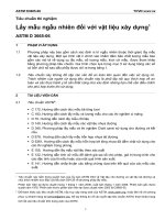
13. Precision and Bias3
13.1 The precision of this test method as determined by
statistical examination of interlaboratory results is as follows:
13.1.1 Repeatability—The difference between two test
results, obtained by the same operator with the same apparatus
under constant operating conditions on identical test material
would, in the long run, in the normal and correct operation of
the test method, exceed the values shown in Fig. 2 only in one
case in twenty.
13.1.2 Reproducibility—The difference between two single
and independent results obtained by different operators working in different laboratories on identical test material would, in
the long run, in the normal and correct operation of the test
method, exceed the values shown in Fig. 2 only in one case in
twenty.
10.3 Place a volume of sample equivalent to 200 mL at 13
to 18°C in the flask. Maintain the condenser bath at 0 to 4°C
(for some oils it may be necessary to hold the temperature
between 38 and 60°C to avoid solidification of waxy material
in the condenser tube). Use, without cleaning, the cylinder
from which the sample was measured as the receiver and place
it so that the tip of the condenser does not touch the wall of the
cylinder.
10.4 Apply the heat to the flask at a uniform rate so
regulated that the first drop of condensate exits from the
condenser between 10 and 15 min after initial application of
heat. After the first drop falls, move the receiving cylinder so
that the tip of the condenser tube touches the wall of the
cylinder. Then regulate the heat so that the distillation proceeds
at a uniform rate of 8 to 10 mL/min. Continue the distillation
until 178 mL of distillate has been collected, then discontinue
heating and allow the condenser to drain until 180 mL (90 % of
the charge to the flask) has been collected in the cylinder.
NOTE 6—Precision is based on data developed using inch-pound units.
See Test Method D189–76.
13.2 Bias—This test method is based on empirical results
and no statement of bias can be made.
10.5 Immediately replace the cylinder with a small Erlenmeyer flask and catch any final drainage in the flask. Add to
this flask, while still warm, the distillation residue left in the
distilling flask, and mix well. The contents of the flask then
represents a 10 % distillation residue from the original product.
14. Keywords
14.1 Conradson carbon residue; lubricants; petroleum
products
3
Supporting data have been filed at ASTM International Headquarters and may
be obtained by requesting Research Report RR:D02-1227. Additional data used for
the precision statement were obtained from the NRC, pending permission to reprint.
10.6 While the distillation residue is warm enough to flow
freely, pour approximately 10 6 0.5 g of it in the previously
4
D189 − 06 (2014)
Log r = −0.91666 + 0.82504 Log x + 0.08239 (Log x) 2
Log R = −0.62668 + 0.72403 Log x + 0.10730 (Log x)2
x = average of results being compared
FIG. 2 Precision
APPENDIX
(Nonmandatory Information)
X1. INFORMATION CONCERNING CORRELATION OF CARBON RESIDUE RESULTS DETERMINED BY TEST METHODS
D189, D524, AND D4530
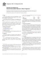
X1.2 A direct correlation of the results obtained by Test
Methods D189 and D4530 has been derived by ASTM Committee D02 as shown in Fig. X1.2. Supporting data have been
filed at ASTM Headquarters.4
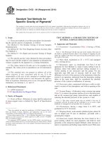
X1.1 No exact correlation of the results obtained by Test
Methods D189 and D524 exists because of the empirical nature
of the two tests. However, an approximate correlation (Fig.
X1.1) has been derived by ASTM Committee D02 from the
cooperative testing of 18 representative petroleum products
and confirmed by further data on about 150 samples which
were not tested cooperatively. Test results by both methods on
unusual types of petroleum products need not fall near the
correlation line of Fig. X1.1.
Caution should be exercised in the application of this
approximate relation to samples of low carbon residues.
4
Supporting data have been filed at ASTM International Headquarters and may
be obtained by requesting Research Report RR:D02-1192.
5
D189 − 06 (2014)
FIG. X1.1 Correlation Data
FIG. X1.2 Correlation of Conradson and Micro Carbon Residue Tests
6
D189 − 06 (2014)
ASTM International takes no position respecting the validity of any patent rights asserted in connection with any item mentioned
in this standard. Users of this standard are expressly advised that determination of the validity of any such patent rights, and the risk
of infringement of such rights, are entirely their own responsibility.
This standard is subject to revision at any time by the responsible technical committee and must be reviewed every five years and
if not revised, either reapproved or withdrawn. Your comments are invited either for revision of this standard or for additional standards
and should be addressed to ASTM International Headquarters. Your comments will receive careful consideration at a meeting of the
responsible technical committee, which you may attend. If you feel that your comments have not received a fair hearing you should
make your views known to the ASTM Committee on Standards, at the address shown below.
This standard is copyrighted by ASTM International, 100 Barr Harbor Drive, PO Box C700, West Conshohocken, PA 19428-2959,
United States. Individual reprints (single or multiple copies) of this standard may be obtained by contacting ASTM at the above
address or at 610-832-9585 (phone), 610-832-9555 (fax), or (e-mail); or through the ASTM website
(www.astm.org). Permission rights to photocopy the standard may also be secured from the Copyright Clearance Center, 222
Rosewood Drive, Danvers, MA 01923, Tel: (978) 646-2600; />
7