bionanofluidic mems
Bạn đang xem bản rút gọn của tài liệu. Xem và tải ngay bản đầy đủ của tài liệu tại đây (6.45 MB, 300 trang )
BioNanoFluidic MEMS
MEMS Reference Shelf
Series Editor: Stephen D. Senturia
Professor of Electrical Engineering, Emeritus
Massachusetts Institute of Technology
Cambridge, Massachusetts
BioNanoFluidic MEMS
Peter Hesketh, ed.
ISBN 978-0-387-46281-3
Microfluidic Technologies for Miniaturized Analysis Systems
Edited by Steffen Hardt and Friedhelm Schöenfeld, eds.
ISBN 978-0-387-28597-9
Forthcoming Titles
Self-assembly from Nano to Milli Scales
Karl F. Böhringer
ISBN 978-0-387-30062-7
Photonic Microsystems
Olav Solgaard
ISBN 978-0-387-29022-5
Micro Electro Mechanical Systems: A Design Approach
Kanakasabapathi Subramanian
ISBN 978-0-387-32476-0
Experimental Characterization Techniques for Micro-Nanoscale Devices
Kimberly L. Turner and Peter G. Hartwell
ISBN 978-0-387-30862-3
Microelectroacoustics: Sensing and Actuation
Mark Sheplak and Peter V. Loeppert
ISBN 978-0-387-32471-5
Inertial Microsensors
Andrei M. Shkel
ISBN 978-0-387-35540-5
Peter J. Hesketh
Editor
BioNanoFluidic MEMS
Editor
Peter J. Hesketh
George W. Woodruff
School of Mechanical Engineering
Georgia Institute of Technology
Atlanta, GA 30332-0405
ISBN: 978-0-387-46281-3 e-ISBN: 978-0-387-46283-7
Library of Congress Control Number: 2007932882
c
2008 Springer Science+Business Media, LLC
All rights reserved. This work may not be translated or copied in whole or in part without the written
permission of the publisher (Springer Science+Business Media, LLC., 233 Spring Street, New York,
NY10013, USA), except for brief excerpts in connection with reviews or scholarly analysis. Use in
connection with any form of information storage and retrieval, electronic adaptation, computer software,
or by similar or dissimilar methodology now known or hereafter developed is forbidden.
The use in this publication of trade names, trademarks, service marks, and similar terms, even if they are
not identified as such, is not to be taken as an expression of opinion as to whether or not they are subject to
proprietary rights.
Printed on acid-free paper
987654321
springer.com
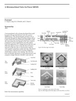
Preface
This collaboration evolved from contributions by faculty members who participated
in workshops on NanoBioFluidic Micro Electro-Mechanical Systems (MEMS) at
the Georgia Institute of Technology, Atlanta, Georgia, in November,2005 and June,
2006. The objectiveof these workshopswas to bringtogetherresearchers, engineers,
faculty, and students to review the interdisciplinary topics related to miniaturization
and to nanomaterials processing, with a particular emphasis on the development
of sensors and microfluidic systems. The workshops were events attended by par-
ticipants from industry and academia, with lectures, hands-on laboratory sessions,
student poster sessions, and panel discussions.
These chapters cover current research topics pertinent to the field, including:
materials synthesis, nanofabrication methods, nanoscale structures’ properties,
nanopores, nanomaterial-based chemical sensors, biomedical applications, and
nanodevice packaging. The emphasis has been placed on a review of fundamental
principles, thereby providing an introduction to nanodevice fabrication methods.
Supporting this background are discussions of recent developments and a selection
of practical applications.
It should be noted that NanoBioFluidic MEMS is an enormously broad field of
study, and any survey must of necessity be selective. Taken individually, topics cho-
sen for inclusion in this volume may of be most benefit to those working within the
corresponding area. Nevertheless, the aggregate of specific topic selections within
this compilation should provide an effective overview of this vast, highly interdis-
ciplinary subject, and hopefully, a glimpse into the magnitude of possibilities at the
nanoscale.
The enormity of the potential for nanodevices and miniature systems cannot
be overstated. An understanding of these possibilities is the first step toward the
realization of practical applications and solutions to important problems in health
care, agriculture, manufacturing, and the pharmaceuticals industry, among many
others. The evolution of these applications will bring about such advancements
as novel sensor technologies capable of contributing to such vital undertakings as
the reduction of pollution and its inherent impact on global warming, and to any
number of comparably imperative enterprises that promise to bring to bear new
approaches to solving significant problems and raising the standard of living for
people worldwide.
vi Preface
Chapter 1 sets the stage by surveying the past and present of core microelectronic
nanotechnology, and addresses its likely future directions. It addresses a central
question: is the most appropriate method for integration based upon traditional top
down methods, or are bottom up methods more appropriate for manufacturing?
Chapter 2 examines the high temperature growth of a range of metal oxide nanos-
tructures that form nanobelts, nanowires, and nanorods. These materials exhibit
notably unique properties of special relevance because they become evident at the
nanoscale size. These materials represent an example of a broad class of nanomate-
rials that promise suitability for integration with microelectronics.
Chapter 3 discusses direct write lithographymethods and their processing advan-
tages and limitations.
Chapter 4 presents an introduction to and an overview of nanofabrication
methods.
Chapter 5 examines emerging nanoimprinting methods.
Chapter 6 describes methods for nondestructive nanoscale material
characterization.
Chapter 7 addresses the use of micro stereo-lithography. Micro- and nanodevices
need to be connected to the outside world, and this highly versatile method provides
customized coupling either to individual dies or to arrays, and even to wafer-scale
integrated packaging.
Chapters 8 through 10 survey nanobiofluidic system applications, including case
studies for chemical sensors, nanopores-to-DNA sequencing, and biomaterial cell-
surface interfaces.
Chapter 11 concludes the discussion with anexplorationinto integrationmethods
for fine-pitch electrical connections to nanobiosensors.
I would very much like to thank all of the contributing authors for the timely
submission of their manuscripts and for assisting in reviews of their co-authors’
chapters. Thanks to Philip Duris for editorial suggestions, in particular a detailed
editing of Chapter 4.
It has been a great pleasure to have been a participant in the preparation of this
book, principally because of the involvement of such a knowledgeable group of
faculty and researchers. Theinterdisciplinary nature of this important, dynamic, and
challenging area of research necessitated the contributions of all involved, to whom
I am deeply grateful.
Peter J. Hesketh
Contents
1 Nanotechnology: Retrospect and Prospect 1
James D. Meindl
2 Synthesis of Oxide Nanostructures 11
Chenguo Hu, Hong Liu and Zhong Lin Wang
3 Nanolithography 37
Raghunath Murali
4 Nano/Microfabrication Methods for Sensors and NEMS/MEMS 63
Peter J. Hesketh
5 Micro- and Nanomanufacturing via Molding 131
Harry D. Rowland and William P. King
6 Temperature Measurement of Microdevices using
Thermoreflectance and Raman Thermometry 153
Thomas Beechem and Samuel Graham
7 Stereolithography and Rapid Prototyping 175
David W. Rosen
8 Case Studies in Chemical Sensor Development 197
Gary W. Hunter, Jennifer C. Xu and Darby B. Makel
9 Engineered Nanopores 233
Amir G. Ahmadi and Sankar Nair
10 Engineering Biomaterial Interfaces Through Micro and Nano-
Patterning 251
Joseph L. Charest and William P. King
11 Biosensors Micro and Nano Integration 279
Ravi Doraiswami
viii Contents
About the Cover 291
Index 293
Contributors
Amir G. Ahmadi
School of Chemical & Biomolecular
Engineering
Georgia Institute of Technology
Atlanta GA 30332-0100
Thomas Beechem
The George W. Woodruff
School of Mechanical Engineering
Georgia Institute of Technology
Atlanta, GA 30332-0405
Joseph L. Charest
The George W. Woodruff
School of Mechanical Engineering
Georgia Institute of Technology
Atlanta, GA 30332-0405
Ravi Doraiswami
The George W. Woodruff
School of Mechanical Engineering
Georgia Institute of Technology
Atlanta, GA 30332-0405
Samuel Graham
The George W. Woodruff
School of Mechanical Engineering
Georgia Institute of Technology
Atlanta, GA 30332-0405
Peter J. Hesketh
The George W. Woodruff
School of Mechanical Engineering
Georgia Institute of Technology
Atlanta, GA 30332
USA, (404)385-1358
Chenguo Hu
School of Materials
Science and Engineering
Georgia Institute of Technology
Atlanta, GA 30332-0245
USA;
Department of Applied Physics
Chongqing University
Chongqing 400044
China
Gary W. Hunter
NASA Glenn Research
Center at Lewis Field
Cleveland, OH 44135
William P. King
Department of Mechanical
Science and Engineering
University of Illinois
Urbana-Champaign
Urbana, IL 61801, USA
Hong Liu
School of Materials
Science and Engineering
Georgia Institute of Technology
Atlanta, GA 30332-0245
USA;
State Key Laboratory
of Crystal Materials
Shandong University
Jinan 250100
China
x Contributors
Darby B. Makel
Makel Engineering, Inc.,
1585 Marauder St.
Chico, CA 95973
James D. Meindl
School of Electrical and
Computer Engineering
Georgia Institute of Technology
Atlanta, GA 30332
USA
Raghunath Murali
School of Electrical and
Computer Engineering
Georgia Institute of Technology
Atlanta, GA 30332
USA
Sankar Nair
School of Chemical & Biomolecular
Engineering
Georgia Institute of Technology
Atlanta GA 30332-0100
Harry D. Rowland
The George W. Woodruff
School of Mechanical Engineering
Georgia Institute of Technology
Atlanta, GA 30332
USA
David W. Rosen
The George W. Woodruff
School of Mechanical Engineering
Georgia Institute of Technology
Atlanta, GA 30332
Zhong Lin Wang
School of Materials
Science and Engineering
Georgia Institute of Technology
Atlanta, GA 30332-0245
USA
Jennifer C. Xu
NASA Glenn
Research Center at Lewis Field
Cleveland, OH 44135
Chapter 1
Nanotechnology: Retrospect and Prospect
James D. Meindl
Abstract The predominant economic event of the 20th century was the informa-
tion revolution. The most powerful engine driving this revolution was the silicon
microchip. During the period from 1960 through 2000, the productivity of semi-
conductor or silicon microchip technology advanced by a factor of approximately
100 million. Concurrently, the performance of the technology advanced by a factor
greater than 1000. These sustained simultaneous advances were fueled primarily
by sequentially scaling down the minimum feature size of the transistors and inter-
connects of a microchip thereby both reducing cost and enhancing performance. In
2005 minimum feature sizes of 80 nanometers clearly indicate that microchip tech-
nology has entered the 1–100nanometer domain of nanotechnologythroughuse of a
“top-down” approach. Moreover, it is revealing to recognize that the 300-millimeter
diameter silicon wafers, which facilitate microchip manufacturing, are sliced from
a 1–2 meter long single crystal ingot of hyper-puresilicon. This silicon ingot is pro-
duced by a “self–assembly” process that represents the essence of the “bottom-up”
approach to nanotechnology. Consequently, modern silicon microchips containing
over one billion transistors are enabled by a quintessential fusion of top-down and
bottom-up nanotechnology.
Due to factors such as transistor leakage currents and short-channel effects,
critical dimension control tolerances, increasing interconnect latency and switch-
ing energy dissipation relative to transistors, escalating chip power dissipation and
heat removal demands as well as design, verification and testing complexity, it
appears that the rate of advance of silicon microchip technology may decline dras-
tically within the next 1–2 decades. Nanotechnology presents a generic opportu-
nity to overcome the formidable barriers to maintaining the historical rapid rate of
advance of microchip technologyandconsequentlythe informationrevolutionitself.
The breakthroughs that are needed are unlikely without a concerted global effort
on the part of industries, universities and governments. Nurturing such an effort
J. D. Meindl
School of Electrical and Computer Engineering, Georgia Institute of Technology, Atlanta,
GA 30332, USA
P. J. Hesketh (ed.), BioNanoFluidic MEMS.
C
Springer 2008
2 J. D. Meindl
is profoundly motivated by the ensuing prospect of enhancing to unprecedented
levels the quality of life of all people of the world.
1.1 Introduction
Beginning about10,000years ago in the Middle East, the agricultural revolutionwas
a crucial development in human history. This revolution enabled the accumulation
of surplus food supplies, which gave rise to large settlements and the emergence of
Western civilization itself.
The industrial revolution that began in the 18th century in Europe was the most
far-reaching, influential transformation of human culture following the agricultural
revolution. The consequences of the industrial revolution have changed irrevoca-
bly human labor, consumption and family structure; it has caused profound social
changes, as Europe movedfrom a primarily agricultural and rural economy to a cap-
italist and urban economy. Society changed rapidly from a family-based economy
to an industry-based economy.
The informationrevolution was the predominant economic event of the 20th cen-
tury and promises to continue well into the 21st century and beyond. It has given
us the personal computer, the multi-media cell phone, the Internet and countless
other electronic marvels that influence our daily lives. The explosive emergence of
the Internet and its potential to create a global information infrastructure, a global
educational system and a global economy provide a unique opportunity to improve
the quality of life of all people to unprecedented levels.
1.2 In Retrospect
Perhaps the three most prominent inventions that collectively launched the informa-
tion revolution were the transistor in 1947 [1], the stored program digital computer
in 1945 [2] and the silicon monolithic integrated circuit or “microchip” in 1958 [3].
The single most powerful engine driving the information revolution has been the
silicon microchip for two compelling reasons, productivity and performance. For
example, from 1960 through 2000, the productivity of silicon technology improved
by a factor or more than 100 million [4, 5]. This is evident from the fact that the
number of transistors contained within a microchip increased from a handful in
1960 to several hundred million in 2000, while the cost of a microchip remained
virtually constant. Concurrently, the performance of a microchip improved by a
factor of more than 1,000 [6]. These simultaneous sustained exponential rates of
improvement in both productivity and performance are unprecedented in techno-
logical history.
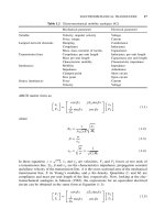
The most revealing microchip productivity metric, the number of transistors per
microchip, N, can be quantified by a simple mathematical expression: N = F
–
2
•D
2
•PE where F is the minimum feature size of a transistor, D
2
is the area of
the microchip and PE is the transistor packing efficiency in units of transistors per
1 Nanotechnology: Retrospect and Prospect 3
minimum feature square or [tr/F
2
] [7]. One can graph log
2
vs. calendar year, Y, and
then take the derivative of the plot, d(log
2
N)/dY, to observe that N doubled every
12 months in the early decades of the microchip [4,8] and every 18 months in more
recent decades [8]. This incisive observation is now quite widely known as Moore’s
Law [9].
The minimum feature size of a transistor, F, has been reduced at a rapid rate
throughout the entire history of the microchip [9, 10] and is projected to con-
tinue to decrease for at least another decade [11]. Chip area, D
2
, increased less
rapidly than F
−2
in the early decades of the microchip [9,10] and maximum chip
area is projected to saturate for future generations of technology [11]. Packing
efficiency, PE, has increased monotonically throughout the entire history of the
microchip but at a considerably smaller rate than F
−2
[9–11]. The key observation
regarding F, D and PE is that reducing the minimum feature size of a transistor,
F, or “scaling” has been the most effective means of increasing the number of
transistors per chip, N, and consequently improving the productivity of microchip
technology.
The most appropriatemetric for gaugingthe performanceof a microchip depends
greatly on its particular product application. For a microprocessor, the number of
instructions per second, IPS, executed by the chip is a commonly used performance
metric [12]. A useful mathematical relationship for this metric is: IPS = IPC •f
C
where IPC is number of instructions per cycle and f
C
is the number of cycles
per second or clock frequency of the chip. The IPC executed by a microproces-
sor depends strongly on both the hardware microarchitecture of the chip and its
software instruction set architecture. Throughout the history of the microprocessor
its microarchitecture has been influenced significantly by the capabilities and lim-
itations of silicon monolithic microchip technology [12]. This has become quite
evident with the recent advent of the chip multiprocessor (or cell microprocessor),
CMP, [13,14],which consists of a (growing)number of complex cells each of which
is effectively a microprocessor. The principal purpose of the CMP is to increase the
number of instructions per cycle, IPC, executed by the chip. The microarchitecture
of a chip multiprocessor is particularly enabled by the cost and latency reductions
resulting directly from reduced feature size or scaling of transistors. Consequently,
it is clear that scaling effectively enables increases in IPC.
Moreover,the more than 1,000times increaseof microprocessorclock frequency,
f
C
, from approximately one megahertz in the early 1970’s to greater than one giga-
hertz in the past several years has been driven primarily by feature size and con-
sequent latency reductions due to transistor scaling. In addition, circuit innovations
have promoted increasing clock frequencies. Again, the key observation is that scal-
ing has been a most effective means of increasing both IPC and f
C
and consequently
the performance, IPS, of a microprocessor.
The salient conclusion of the preceding review of microchip productivity, N,
and performance, IPS, is that scaling has been the most effective means for their
enormous advancements. Scaling has been the most potent “fuel” energizing the
microchip engine, which has been the most powerful driver of the information
revolution.
4 J. D. Meindl
Throughout the nearly five-decade history of the silicon microchip, its “pac-
ing” technology has been microlithography, which enables scaling. For example,
in 1960 the minimum feature size, F, of a microchip transistor was approximately
25m; by 2000, F had scaled down over two decades to a value of 0.25m; and in
2005 transistor printed gate length is 45 nanometers, nm, and copper interconnect
half pitch is 80nm [11]. In addition, current field effect transistor gate oxynitride
insulator thickness is in the 1.5 nm range. These 2005 transistor and intercon-
nect dimensions clearly indicate that silicon microchips have entered the 1.0–100
nanometer domain of nanotechnology [15].
The entry of the microchip into the realm of nanotechnology has been accom-
plished by exploiting a “top-down” approach. Transistor and interconnect dimen-
sions have been sequentially scaled down for more than four decades through a
continuing learning process. However, viewing the development of silicon technol-
ogy from this perspective alone could be misleading. It is revealing to recognize
that modern silicon microchip manufacturing begins with a 300-millimeter (mm)
diameter wafer that is sliced from a single crystal ingot of silicon, which is 1–2
meters in length. The density of atoms in this ingot is 5×10
22
/cm
3
and the atomic
spacing is 0.236 nm. Perhaps the most interesting feature of this ingot is that it
is entirely “self-assembled” atom-by-atom during its growth by the Czochralski
process [16]. This process has been used for volume production of silicon crystals
since the mid-1950s. It is patently “bottom-up” nanotechnology. Consequently, in
2005, silicon microchips exploit a quintessential fusion of top-down and bottom-
up nanotechnology. This fusion has been and remains paramount to the success of
microchip technology.
1.3 In Prospect
In projections regardingthe prospects of nanotechnologyas applied to gigascale and
terascale levels of integration for future generationsof microchips, it is interesting to
consider a scenario that postulates a continuing fusion of top-down and bottom-up
approaches. Without a virtually perfect single-crystal starting material it is difficult
to project batch fabrication of billions and trillions of sub-10 nm minimum feature
size binary switching elements (i.e. future transistors) in a low cost microchip. It
is equally difficult to imagine the purposeful design, verification and testing of a
multi-trillion transistor computing chip without a disciplined top-down approach.
Consequently, this particular prospective is based on the premise of a fusion of
top-down and bottom-up nanotechnology with the target of advancing the infor-
mation revolution for another half-century or more. Discussion of the prospects
of nanotechnology begins with an assessment of the most serious obstacles now
confronting silicon microchip technology as it continues to progress more deeply
into the nanotechnology space. Subsequently, a tentative projection of the salient
challenges and opportunities for overcoming these obstacles through nanotechnol-
ogy and more specifically through carbon nanotube technology is outlined.
1 Nanotechnology: Retrospect and Prospect 5
A selected group of grand challenges that must be met in order to sustain the
historic rate of progress of silicon microchip technology includes the following:
1) field effect transistor (FET) gate tunneling currents a) that are increasing rapidly
due to the compelling need for scaling gate insulator thickness and b) that serve
only to heat the microchip and drain battery energy; 2) FET threshold voltage that
rolls-off exponentially below a critical value of channel length and consequently
strongly increases FET subthreshold leakage current without benefit; 3) FET sub-
threshold swing that rolls-up exponentially below a critical channel length and con-
sequently strongly reduces transistor drive current and therefore switching speed; 4)
critical dimension tolerances that are increasing with scaling and therefore endan-
gering large manufacturing yields and low cost chips; 5) interconnect latency and
switching energy dissipation that now supercede transistor latency and switching
energy dissipation and this supercession will only be exacerbated as scaling con-
tinues; 6) chip power dissipation and heat removal limitations that now impose the
major barrier to enhancement of chip performance; and 7) rapidly escalating design,
verification and testing complexity that threatens the economics of silicon microchip
technology.
Although the preceding grand challenges appear daunting, prospects for meet-
ing them are encouraging due to the exciting opportunities of nanotechnology as
eloquently summarized in the words of Professor Richard Feynman [17]: “There
is plenty of room at the bottom.” In 1959 he articulated an inspiring vision of nan-
otechnology[17]:“The principlesof physics, as faras I can see, do not speak against
the possibility of maneuvering things atom by atom. It is not an attempt to violate
any laws; it is something, in principle, that can be done; but in practice, it has not
been done because we are too big.”
Several relatively recent advances in nanotechnology reveal encouraging
progress toward fulfillment of Feynman’s vision. First among these advances
was the invention of the scanning tunneling microscope in 1981 by Binnig
and Rohrer [18]. This novel measurement tool is capable of imaging individual
atoms on the surface of a crystal and thus providing a new level of capability to
understand what is being built “atom by atom.” A second major advance was the
discovery of self-assembled geodesic nanospheres of 60 carbon atoms in 1985 by
Smalley [19]. A third was the discovery of self-assembled carbon nanotubes in
1990 by Iijima [20]. A fourth was the demonstration, by two separate teams, of
carbon nanotube transistors in 1998 [21, 22]. The latter three of these advances
deal with carbon nanostructures, which currently represent the particular area of
nanotechnology that has been most widely investigated as a potential successor
(or extender) of mainstream silicon microchip technology. Consequently, this
discussion now focuses on carbon nanotube (CNT) technology as a prime example
of the prospects of nanotechnology.
Key challenges that carbonnanotubetechnologymust meet if it is to proveuseful
for gigascale and terascale levels of integration can be summarized succinctly in
two words: precise control. Precise control must be achieved of: 1) CNT transistor
placement; 2) CNT transistor semiconductor properties or chirality; 3) precise con-
trol of CNT interconnect placement; 4) precise control of CNT interconnect metallic
6 J. D. Meindl
properties or chirality; and 5) precise control of semiconductor and metallic junc-
tions. A historical analogy serves to elucidate the comparative state-of-the-art of
CNT technology. This analogy suggests that the current status of CNT technology
is comparable to that of early semiconductortechnologybetween the 1947 invention
of the point contact transistor [1] and the 1958 invention of the silicon monolithic
integrated circuit or microchip [3]. A lack of the necessary degree of control to
fabricate a monolithic integrated circuit is reflected in the two striking scanning
electron micrographs illustrated in Fig. 1.1 [23]. The conclusion of this analogical
comparison is that the first critical step in the advancement of CNT technology has
been demonstrated but not (yet) the second.
Based on progress to date several rather promising characteristics of CNT tran-
sistors and interconnects can be identified. The first of these is the potential for
CNT transistors with a subthreshold swing, S, less than the fundamental limit of S
= (kT/q)ln2 = 60mV/decade on FET transistor subthreshold swing at room temper-
ature, where k is Boltzman’s constant, T is temperature in degrees Kelvin and q is
the electronic charge. CNT transistors with room temperature S ≈ 40 mV/decade
have recently been reported [24]. The benefits of smaller S are manifold. A perfor-
mance improvement is in prospect due to the opportunity to reduce binary signal
swing and thus reduce transistor latency. A reduction in switching energy dissi-
pation is quite feasible due to a reduced binary signal swing and supply voltage.
A reduction in static energy dissipation is expected due to a smaller subthreshold
1
Demonstration of 2-D Carbon NanotubeWiring Network
Nanotube Connections
2 µm
500nm
Controlled Assembly of
Multiple Connections
Single-wall Nanotube
Networks of Varying
Density/Pitch
(Courtesy Prof. P. Ajayan)
Fig. 1.1 Demonstration of 2D carbon nanotube wiring network
1 Nanotechnology: Retrospect and Prospect 7
1
Bundles of carbon nanotubes should be used for interconnect applications
Bundles of carbon nanotubes should be used for interconnect applications
to avoid very slow signal propagation.
to avoid very slow signal propagation.
Ideal Carbon Nanotubes versus Copper Wires in 2016 (22nm Node)
Ideal Carbon Nanotubes versus Copper Wires in 2016 (22nm Node)
(Naeemi, Meindl –GIT)
Fig. 1.2 Ideal carbon nanotubes compared with copper wires in 2016 (22 nm node)
leakage current resulting from a reduced S. A second promising characteristic of
CNT transistors would be smaller transistor gate and channel lengths. Shorter chan-
nels should reduce carrier transit time and thus device switching latency. A third
major advantage would be CNT interconnectwith smaller latency than copperwires
due to ballistic carrier transport in nanotubes in contrast to the multiple scattering
of carriers in polycrystalline copper interconnects. A comparison of interconnect
latency versus length for both CNTs and copper wires is illustrated in Fig. 1.2 [25].
A rather demanding requirement that Fig. 1.2 reveals is that for CNT intercon-
nects to achieve smaller latency than copper wires at the 22 nm node of silicon
microchip technology,projected for 2016by the ITRS [11], precise control of place-
ment and chirality of a bundle of 100 CNTs each 2 nm in diameter appears to be
necessary.
In summary, the potential advantages of CNT technology discussed above
could result in substantial improvements in microchips including greater speed,
reduced dynamic and static energy dissipation as well as smaller size and therefore
lower cost.
1.4 Conclusion
The key conclusion that emerges from the foregoing retrospective and prospective
reviews of nanotechnology is that apparently it represents our best prospect for
continuing the exponential rate of advance of the information revolution. Recent
8 J. D. Meindl
participation of representatives of corporations, universities and governments in the
US, Europe and Japan in the First International Conference on Nanotechnology
confirms this conclusion [26]. The implications of continuing this exponential rate
of advance to the mid-21st century and beyond are utterly profound. Perhaps the
most magnificent prospect is that through continued rapid development of a global
information infrastructure, a global educational system and a thriving global
economy, the quality of life of all people of the world may be enhanced to
unprecedented levels!
References
1. Ross, I. M. (1998). The Invention of the Transistor. Proceedings of the IEEE: Special Issue:
50th Anniversary of the Transistor, 28, 7–28.
2. Seitz, F., & Einspruch, N. (1998). Electronic Genie: The Tangled History of Silicon. Urbana
and Chicago, IL: University of Illinois Press.
3. Kilby, J. S. (1959). U.S. Patent No. 3,138,743. Washington, DC: U.S. Patent and Trademark
Office.
4. Moore, G. E. (1965, April 19). Cramming More Components onto Integrated Circuits. Elec-
tronics, 38, No. 8.
5. Takai, Y., et al. (1999). A 250Mb/s/pin 1GB Double Data Rate SDRAM with a Bi-directional
Delay and an Inter-bank Shared Redundancy Scheme. IEEE International Solid-state Circuits
Conference, February 15–17, (pp. 418–419). Augusta, ME: The J. S. McCarthy Co.
6. Thompson, S., et al. (2002, May 16). 130nm Logic Technology Featuring 60nm Transistors,
Low-K Dielectrics and Cu Interconnects. Intel Technology Journal: Semiconductor Technol-
ogy and Manufacturing, 6(2), 5–13.
7. Meindl, J. (1993). Evolution of Solid-State Circuits: 1958-1992-20??, Digest of Papers, IEEE
International Solid-State Circuits Conference, February 24–26, (pp. 23–26).
8. Moore, G. E. (2003). No Exponential is Forever: But “Forever” can be Delayed! IEEE
International Solid-State Circuits Conference, February 9–13, (20–23). Augusta, ME: J. S.
McCarthy Printers.
9. Moore, G. E. (2003). Progress in Digital Integrated Electronics, Technical Digest of IEEE
International Electron Devices Meeting, p. 11, Dec. 1975.
10. Meindl, J. D. “Theoretical, Practical and Analogical Limits in ULSI”, Technical Digest, IEEE
International Electron Devices Meeting, pp. 8–13, Dec. 1983.
11. Tokyo, J. (2004). International Technology Roadmap for Semiconductors Update.
December 1.
12. Hennessy, J. L., & Patterson, D. A. (1990). Computer Architecture: A Quantitative Approach,
San Mateo, CA: Morgan Kaufmann Publishers, Inc.
13. Naffziger, S., et. al. (2005). The Implementation of a 2-core Multi-Threaded Itanium
R
-Family
Processor, IEEE Solid-State Circuits Conference, February 6–10, (pp. 182–183). Lisbon Falls,
Maine: S
3
Digital Publishing, Inc.
14. Pham, D., et al. (2005). The Design and Implementation of a First-Generation CELL Pro-
cessor, IEEE Solid State Circuits Conference, February 6–10, (pp. 184–185). Lisbon Falls,
Maine: S
3
Digital Publishing, Inc.
15. Nanoscale Science, Engineering and Technology Subcommittee. (2004). The National Nan-
otechnology Initiative Strategic Plan. Washington, DC: National Science and Technology
Council.
16. Huff, H. R. (1997). Twentieth Centery Silicon Microelectronics, ULSI Science and Technol-
ogy/1997, ECS PV 97-3, 53–117.
17. Feynman, R. P. (1992). There’s Plenty of Room at the Bottom. Journal of Microelectrome-
chanical Systems. 1
(1), 60–66.
1 Nanotechnology: Retrospect and Prospect 9
18. Binnig, H. G., Rohrer, C. G., & Weibel, E. (1981). Tunneling through a controllable vacuum
gap. Applied Physics Letters, 40(2), 178–180.
19. Kroto, H. W., Heath, J. R., O’Brien, S. C., Curl, R. F., & Smalley, R. E. (1985). C
60
: Buck-
minsterfullerene. Nature, 318, 162–163.
20. Ijiima, S. (1991). Helical microtubules of graphitic carbon. Nature, 354, 56–58.
21. Tans, Sander J, Verschueren, Alwyin R. M., Dekker, C. (1998). Room-temperature transistor
based on a single carbon nanotube. Nature, 393, 49–52.
22. Martel, R., Schmidt, T., Shea, H. R., Hertel, T., & Avouris, Ph. (1998). Single- and multi-wall
carbon nanotube filed-effect transistors. Applied Physics Letters, 73(17), 2447–2449.
23. Jung, Y., et al. (2003). High-Density, large-Area Single-Walled Carbon Nanotube Networks
on nanoscale Patterned substrates. Journal of Physical Chemistry, 107, 6859–6864.
24. Appenzeller, J., Lin, Y. M., Knoch, J., & Avouris, Ph. (2004). Band-to-Band Tunneling in Car-
bon Nanotube Field-Effect Transistors. Physical Review Letters, 93(19), 196805-1-196805-4.
25. Naeemi, A., Sarvari, R., & Meindl, J. D. (2004). Performance Comparison between Carbon
Nanotube and Copper Interconnects for GSI. IEEE International Electron Devices Meeting.
December 13–15, 29.5.1–29.5.4.
26. San Francisco, C. A. (2005). First International Nanotechnology Conference on Communica-
tion and Cooperation. June 1–3.
27. Kirihata, T., et al. (1999). A 390mm
2
16 Bank 1 Gb DDR SDRAM with Hybrid Bitline Archi-
tecture. IEEE International Solid-State Circuits Conference, February 15–17, (pp. 422–423).
Augusta, ME: The J. S. McCarthy Co.
28. Noyce, R. N. (1959). U.S. Patent No. 2,981,877. Washington, DC: U.S. Patent and Trademark
Office.
Chapter 2
Synthesis of Oxide Nanostructures
Chenguo Hu, Hong Liu and Zhong Lin Wang*
Abstract Growth of oxide nanostructures is an important part of nanomatirials
research, and it is the fundamental for fabricating various nanodevices. This chapter
introduces the four main growth processes for synthesizing oxide nanostructures:
hydrothermal synthesis, vapor-liquid-solid(VLS), vapor-solid (VS) and composite-
hydroxide mediated synthesis. Detailed examples will be provided to illustrate
the uniqueness and applications of these techniques for growing oxide nanowires,
nanobelts and nanorods.
Keywords: Hydrothermal synthesis · Vapor-liquid-solid·Vapor-solid · Composite-
hydroxide mediated · ZnO · BaTiO
3
· Nanobelts, Nanowires, Nanorods
Abbreviation
CHM-Composite hydroxidemediated, MMH-Microemulsion-mediated hydrother-
mal, VS-Vapor solid, VLS-Vapor liquid solid, HRTEM-High resolution transmis-
sion electron microscope, XRD-X-ray Diffraction
2.1 Introduction
Functional oxides are probably the most diverse and rich materials that have
important applications in science and technology for ferromagnetism, ferroelectric-
ity, piezoelectricity, superconductivity, magnetoresistivity, photonics, separation,
catalysis, environmental engineering, etc. [1] Functional oxides have two unique
structural features: switchable and/or mixed cation valences, and adjustable oxygen
deficiency, which are the bases for creating many novel materials with unique
electronic, optical, and chemical properties. The oxides are usually made into
Z. L. Wang
School of Materials Science and Engineering Georgia Institute of Technology, Atlanta, GA
30332-0245, USA
e-mail:
P. J. Hesketh (ed.), BioNanoFluidic MEMS.
C
Springer 2008
12 C. Hu et al.
nanoparticles or thin films in an effort to enhance their surface sensitivity, and they
have recently been successfully synthesized into nanowire-like structures. Utilizing
the high surface area of nanowire-like structures, it may be possible to fabricate
nano-scale devices with superior performance and sensitivity. This chapter reviews
the general techniques used for growing one-dimensional oxide nanostructures.
2.2 Synthesis Methods
2.2.1 VS Growth
The vapor phase evaporation represents the simplest method for the synthesis of
one-dimensional oxide nanostructures. The syntheses were usually conducted in a
tube furnace as that schematically shown in Fig. 2.1 [2]. The desired source oxide
materials (usually in the form of powders) were placed at the center of an alumina or
quartz tube that was inserted in a horizontal tube furnace, where the temperatures,
pressure, and evaporation time were controlled. Before evaporation, the reaction
chamber was evacuated to ∼1–3×10
–
3
Torr by a mechanical rotary pump. At the
reaction temperature, the source materials were heated and evaporated, and the
vapor was transported by the carrier gas (such as Ar) to the downstream end of
the tube, and finally deposited onto either a growth substrate or the inner wall of the
alumina or quartz tube.
For the vapor phase evaporation method, the experiments were usually carried
out at a high temperature (>800
◦
C) due to the high melting point and low vapor
pressure of the oxide materials. In order to reduce the reaction temperature, a mixed
source material, in which a reduction reaction was involved, was employed. For
example, Huang et al. [3] obtained ZnO nanowires by heating a 1:1 mixture of ZnO
and graphite powders at 900−925
◦
C under a constant flow of Ar for 5–30 minutes.
In addition, the reaction temperature can be further reduced when the low melting
point metal that is the cation of the final oxide compound was heated in an oxidized
atmosphere.
Fig. 2.1 Schematic experimental setup for the growth of one-dimensional oxide nanostructures via
an evaporation-based synthetic method
2 Synthesis of Oxide Nanostructures 13
Fig. 2.2 SEM image of ZnO nanobelts. The inset is a TEM image showing the morphological
feature of the nanobelts
Figure 2.2 shows the vapor-solid process synthesized ZnO nanobelts. The as-
synthesized nanobelts have extremely long length and they are dispersed on the
substrate surface. The nanobelt has a rectangular cross-section and uniform shape.
The quasi- one dimension structure and uniform shape are a fundamental ingredient
for fabrication of advanced devices.
2.2.2 VLS Growth
The growth of one-dimensional oxide nanostructures via vapor phase evaporation
may occur with or without catalyst. The feature of the catalyzed-grown nanowires
is that a catalyst nanoparticle is always present at one end of the nanowires. The
function of the catalyst during nanowire growth is to form a low melting point
eutectic alloy with the nanowire materials, which acts as a preferential site for
absorption of gas-phase reactant and, when supersaturated, the nucleation site for
crystallization. During growth, the catalyst particle directs the nanowire’s growth
direction and defines the diameter of the crystalline nanowires. The growth of the
nanowires catalyzed by a catalyst particle follows a mechanism called vapor-liquid-
solid (VLS), which was proposed by Wagner and Ellis in 1964 for silicon whisker
growth [4].
14 C. Hu et al.
Fig. 2.3 Schematic diagram
showing the growth process
in VLS method
In the VLS process (Fig. 2.3), a liquid alloy droplet composed of metal catalyst
component (such as Au, Fe, etc.) and nanowire component (such as Si, III–V com-
pound, II–V compound, oxide, etc.) is first formed under the reaction conditions.
The metal catalyst can be rationally chosen from the phase diagram by identifying
metals in which the nanowire component elementsare soluble in the liquid phase but
do notformsolid solution. For the 1D oxide nanowiresgrown via a VLS process, the
commonly used catalysts are Au [3], Sn [5], Ga [6], Fe [7], Co [8], and Ni [9]. The
liquid droplet serves as a preferential site for absorption of gas phase reactant and,
when supersaturated, the nucleation site for crystallization. Nanowire growth begins
after the liquid becomes supersaturated in reactant materials and continues as long
as the catalyst alloy remains in a liquid state and the reactant is available. During
growth, the catalyst droplet directs the nanowire’s growth direction and defines the
diameter of the nanowire. Ultimately, the growth terminates when the temperature
is below the eutectic temperature of the catalyst alloy or the reactant is no longer
available. As a result, the nanowires obtained from the VLS process typically have
a solid catalyst nanoparticle at its one end with diameter comparable to that of the
connected nanowires.Thus, one can usually determine whether the nanowire growth
was governed by a VLS process form the fact that if there present a catalyst particle
at one end of the nanowire.
Figure 2.4 shows an array of ZnO nanowire arrays grown by VLS approach on
sapphire substrate. The distribution of the Au catalyst determines the locations of
the grown nanowires, and their vertical alignment is determined by the epitaxial
growth on the substrate surface.
2.2.3 Hydrothermal Synthesis
Hydrothermal synthesis appeared in 19th century and became an industrial tech-
nique for large size quartz crystal growth in 20th century [10]. Recent years,
hydrothermal synthesis method has been widely used for preparation of numerous
kinds of inorganic and organic nanostructures.
Hydrothermal synthesis offers the possibility of one-step synthesis under mild
conditions (typically <300
◦
C) in scientific research and industrial production [11].
It involves a chemical reaction in water above ambient temperature and pressure
in a sealed system. In this system, the state of water is between liquid and steam,
2 Synthesis of Oxide Nanostructures 15
Fig. 2.4 Aligned ZnO nanowires grown by a VLS process
and called as supercritical fluid (Fig. 2.5a). The solubility to the reactants and trans-
portation ability to the ions in the liquid of such a fluid is much better than that in
water. Therefore, some reactions that are impossible to carry on in water in ambient
atmosphere can happen at a hydrothermal condition. Normally, hydrothermal syn-
thesis process is a one-step reaction. All the reactants with water are added into the
autoclave. The reaction occurs in the sealed autoclave when the system is heated,
and the nanostructures can be obtained after the autoclave cooled down.
During the reaction, temperature of the reaction system and the pressure in the
autoclave are very important for the reaction results, such as the phase and mor-
phology of the product. The amount of water percentage in the vessel determines
the prevailing experimental pressure at a certain temperature [12]. In hydrothermal
systems, the dielectric constant and viscosity of water decrease with rising tempera-
ture and increase with rising pressure, the temperature effect predominating[13,14].
Owing to the changes in the dielectric constant and viscosity of water, the increased
temperaturewithin a hydrothermalmediumhas a significant effecton the speciation,
solubility,and transportof solids. Formation of metal oxides through a hydrothermal
method should follow such a principal mechanism: the metal ions in the solution
react with precipitant ions in the solution and form precipitate, and the precipitate
dehydrate or decompound in the solution at a high temperature and form crystalline
metal oxide nanostrucutres [15].