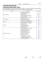
Camry Repair Manual ENGINE MECHANICAL
Bạn đang xem bản rút gọn của tài liệu. Xem và tải ngay bản đầy đủ của tài liệu tại đây (5.45 MB, 226 trang )
EM07X–05
S04994
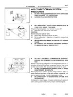
CO/HC Meter
–ENGINE MECHANICAL (5S–FE) CO/HC
EM–1
1173AuthorĂ: DateĂ:
CO/HC
INSPECTION
HINT:
This check is used only to determine whether or not the idle CO/
HC complies with regulations.
1. INITIAL CONDITIONS
(a) Engine at normal operating temperature
(b) Air cleaner installed
(c) All pipes and hoses of air induction system connected
(d) All accessories switched OFF
(e) All vacuum lines properly connected
HINT:
All vacuum hoses for EGR system, etc. should be properly con-
nected.
(f) SFI system wiring connectors fully plugged
(g) Ignition timing checked correctly
(h) Transmission in neutral position
(i) Tachometer and CO/HC meter calibrated by hand
2. START ENGINE
3. RACE ENGINE AT 2,500 RPM FOR APPROX. 180 SE-
CONDS
4. INSERT CO/HC METER TESTING PROBE AT LEAST
40 cm (1.3 ft) INTO TAILPIPE DURING IDLING
5. IMMEDIATELY CHECK CO/HC CONCENTRATION AT
IDLE AND/OR 2,500 RPM
Complete the measuring within 3 minutes.
HINT:
When performing the 2 mode (2,500 rpm and idle) test, follow
the measurement order prescribed by the applicable local regu-
lations.
EM–2
–ENGINE MECHANICAL (5S–FE) CO/HC
1174AuthorĂ: DateĂ:
If the CO/HC concentration does not comply with regulations,
troubleshoot in the order given below.
(1) Check oxygen sensor operation.
(See page DI–66)
(2) See the table below for possible causes, then in-
spect and correct the applicable causes if neces-
sary.
CO HC Symptom Causes
Normal High Rough idle 1. Faulty ignitions:
Incorrect timing
Fouled, shorted or improperly gapped plugs
Open or crossed hi
g
h–tension cords
Oen
or
crossed
high–tension
cords
2. Incorrect valve clearance
3. Leaky EGR valve
4. Leaky intake and exhaust valves
5. Leaky cylinder
Low High Rough idle
(Fluctuating HC reading)
1. Vacuum leaks:
PCV hose
EGR valve
Intake manifold
Throttle body
IAC valve
Brake booster line
2. Lean mixture causing misfire
High High Rough idle
(Black smoke from exhaust)
1. Restricted air filter
2. Faulty SFI system
Faulty pressure regulator
Defective ECT sensor
Defective IAT sensor
Faulty ECM
Faulty injector
Faulty throttle position sensor
MAP sensor
EM07Y–05
S05312
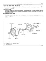
Compression
Gauge
–ENGINE MECHANICAL (5S–FE) COMPRESSION
EM–3
1175AuthorĂ: DateĂ:
COMPRESSION
INSPECTION
HINT:
If there is lack of power, excessive oil consumption or poor fuel
economy, measure the compression pressure.
1. WARM UP AND STOP ENGINE
Allow the engine to warm up to normal operating temperature.
2. DISCONNECT IGNITION COIL CONNECTORS
3. REMOVE SPARK PLUGS (See page IG–1)
4. INSPECT CYLINDER COMPRESSION PRESSURE
(a) Insert a compression gauge into the spark plug hole.
(b) Fully open the throttle.
(c) While cranking the engine, measure the compression
pressure.
HINT:
Always use a fully charged battery to obtain engine speed of
250 rpm or more.
(d) Repeat steps (a) through (c) for each cylinder.
NOTICE:
This measurement must be done in as short a time as pos-
sible.
Compression pressure:
1,226 kPa (12.5 kgf/cm
2
, 178 psi) or more
Minimum pressure: 981 kPa (10.0 kgf/cm
2
, 142 psi)
Difference between each cylinder:
98 kPa (1.0 kgf/cm
2
, 14 psi) or less
(e) If the cylinder compression in one or more cylinders is low,
pour a small amount of engine oil into the cylinder through
the spark plug hole and repeat steps (a) through (c) for
cylinders with low compression.
If adding oil helps the compression, it is likely that
the piston rings and/or cylinder bore are worn or
damaged.
If pressure stays low, a valve may be sticking or
seating is improper, or there may be leakage past
the gasket.
5. REINSTALL SPARK PLUGS (See page IG–1)
6. RECONNECT IGNITION COIL CONNECTORS
EM07Z–03
S05289
(c)
(d)
(e)
S05590
Turn
P03443
11
1122
33
EM–4
–ENGINE MECHANICAL (5S–FE) VALVE CLEARANCE
1176AuthorĂ: DateĂ:
VALVE CLEARANCE
INSPECTION
HINT:
Inspect and adjust the valve clearance when the engine is cold.
1. REMOVE CYLINDER HEAD COVER
(a) Disconnect the 4 high–tension cords from the clamps on
the cylinder head cover.
(b) Disconnect the 4 high–tension cords from the spark
plugs.
(c) Disconnect the PCV hose from the intake manifold.
(d) Disconnect the PCV hose from the cylinder head cover.
(e) Disconnect the engine wire clamp from the mounting bolt
of the No.2 timing belt cover.
(f) Remove the cylinder head cover. (See page EM–33)
2. SET NO.1 CYLINDER TO TDC/COMPRESSION
(a) Turn the crankshaft pulley, and align its groove with timing
mark ”0” of the No.1 timing belt cover.
(b) Check that the valve lifters on the No.1 cylinder are loose
and valve lifters on the No.4 are tight.
If not, turn the crankshaft one revolution (360°) and align the
mark as above.
3. INSPECT VALVE CLEARANCE
(a) Check only the valves indicated.
(1) Using a feeler gauge, measure the clearance be-
tween the valve lifter and camshaft.
(2) Record the out–of–specification valve clearance
measurements. They will be used later to determine
the required replacement adjusting shim.
Valve clearance (Cold):
Intake 0.19 – 0.29 mm (0.007 – 0.011 in.)
Exhaust 0.28 – 0.38 mm (0.011 – 0.015 in.)
(b) Turn the crankshaft one revolution (360°) and align the
mark as above.
P03442
22
33 44
44
P13927
Upward
Cam Lobe
Notch
Spark Plug Side
P13988
Spark Plug Side
SST (A)
SST (B)
P13926
Magnetic
Finger
EM0494
–ENGINE MECHANICAL (5S–FE) VALVE CLEARANCE
EM–5
1177AuthorĂ: DateĂ:
(c) Check only the valves indicated as shown. Measure the
valve clearance. (See step (a))
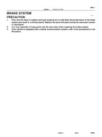
4. ADJUST VALVE CLEARANCE
(a) Remove the adjusting shim.
(1) Turn the crankshaft so that the cam lobe of the cam-
shaft on the adjusting valve points upward.
(2) Position the notch of the valve lifter facing the spark
plug side.
(3) Using SST (A), press down the valve lifter and place
SST (B) between the camshaft and valve lifter. Re-
move SST (A).
SST 09248–55040 (09248–05410, 09248–05420)
HINT:
Apply SST (B) at slight angle on the side marked with ”9”, at the
position shown in the illustration.
(4) Remove the adjusting shim with a small screwdriver
and magnetic finger.
(b) Determine the replacement adjusting shim size by follow-
ing the Formula or Charts:
(1) Using a micrometer, measure the thickness of the
removed shim.
(2) Calculate the thickness of a new shim so that the
valve clearance comes within specified value.
T Thickness of removed shim
A Measured valve clearance
N Thickness of new shim
Intake: N = T + (A – 0.24 mm (0.009 in.))
P13989
SST (A)
SST (B)
S05289
(b)
(c)
(d)
EM–6
–ENGINE MECHANICAL (5S–FE) VALVE CLEARANCE
1178AuthorĂ: DateĂ:
Exhaust: N = T + (A – 0.33 mm (0.013 in.))
(3) Select a new shim with a thickness as close as pos-
sible to the calculated value.
HINT:
Shims are available in 17 sizes in increments of 0.05 mm
(0.0020 in.), from 2.50 mm (0.0984 in.) to 3.30 mm (0.1299 in.).
(c) Install a new adjusting shim.
(1) Place a new adjusting shim on the valve lifter.
(2) Using SST (A), press down the valve lifter and re-
move SST (B).
SST 09248–55040 (09248–05410, 09248–05420)
(d) Recheck the valve clearance.
5. REINSTALL CYLINDER HEAD COVER
(a) Install the cylinder head cover. (See page EM–53)
(b) Connect the PCV hose to the intake manifold.
(c) Connect the PCV hose to the cylinder head cover.
(d) Install the engine wire clamp to the mounting bolt of the
No.2 timing belt cover.
(e) Install the 4 high–tension cords to the clamps on the cylin-
der head cover.
(f) Connect the 4 high–tension cords to the spark plugs.
V00867
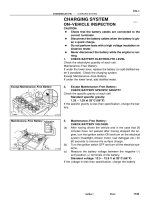
EXAMPLE: The 2.800 mm (0.1102 in.) shim is installed,
and the measured clearance is 0.450 mm (0.0177 in.).
Replace the 2.800 mm (0.1102 in.) shim with a new No.11
shim.
Adjusting Shim Selection Chart (Intake)
Intake valve clearance (Cold):
0.19 – 0.29 mm (0.007 – 0.011 in.)
2.500 (0.0984)
2.550 (0.1004)
2.600 (0.1024)
2.650 (0.1043)
2.700 (0.1063)
2.750 (0.1083)
2.800 (0.1102)
2.850 (0.1122)
2.900 (0.1142)
2.950 (0.1161)
3.000 (0.1181)
3.050 (0.1201)
3.100 (0.1220)
3.150 (0.1240)
3.200 (0.1260)
3.250 (0.1280)
3.300 (0.1299)
Shim
No.
Thickness
Shim
No.
Thickness
4
5
6
7
8
3
2
1
9
10
11
12
13
14
15
16
17
HINT: New shims have the thickness in millimeters
imprinted on the face.
Installed shim thickness
Measured clearance
mm (in.)
mm (in.)
New shim thickness
mm (in.)
–ENGINE MECHANICAL (5S–FE) VALVE CLEARANCE
EM–7
1179AuthorĂ: DateĂ:
V00868
2.500 (0.0984)
2.550 (0.1004)
2.600 (0.1024)
2.650 (0.1043)
2.700 (0.1063)
2.750 (0.1083)
2.800 (0.1102)
2.850 (0.1122)
2.900 (0.1142)
2.950 (0.1161)
3.000 (0.1181)
3.050 (0.1201)
3.100 (0.1220)
3.150 (0.1240)
3.200 (0.1260)
3.250 (0.1280)
3.300 (0.1299)
Shim
No.
Thickness
Shim
No.
Thickness
4
5
6
7
8
3
2
1
9
10
11
12
13
14
15
16
17
HINT: New shims have the thickness in millimeters
imprinted on the face.
Adjusting Shim Selection Chart (Exhaust)
Exhaust valve clearance (Cold):
0.28 – 0.38 mm (0.011 – 0.015 in.)
EXAMPLE: The 2.800 mm (0.1102 in.) shim is installed,
and the measured clearance is 0.450 mm (0.0177 in.).
Replace the 2.800 mm (0.1102 in.) shim with a new No.9
shim.
Installed shim thickness
Measured clearance
mm (in.)
mm (in.)
New shim thickness mm (in.)
EM–8
–ENGINE MECHANICAL (5S–FE) VALVE CLEARANCE
1180AuthorĂ: DateĂ:
EM080–03
S05331
A07370
SST
E1
TE1
S05309
–ENGINE MECHANICAL (5S–FE) IGNITION TIMING
EM–9
1181A uthorĂ: DateĂ:
IGNITION TIMING
INSPECTION
1. WARM UP ENGINE
Allow the engine to warm up to normal operating temperature.
2. CONNECT TOYOTA HAND–HELD TESTER OR OBDII
SCAN TOOL
(a) Remove the fuse cover on the instrument panel.
(b) Connect a TOYOTA hand–held tester or OBDII scan tool
to the DLC3.
(c) Please refer to the TOYOTA hand–held tester or OBDII
scan tool operator’s manual for further details.
3. CONNECT TIMING LIGHT TO ENGINE
4. INSPECT IGNITION TIMING
(a) Using SST, connect terminals TE1 and E1 of the DLC1.
SST 09843–18020
HINT:
After engine rpm is kept at 1,000 – 1,300 rpm for 5 seconds,
check that it returns to idle speed.
(b) Using a timing light, check the ignition timing.
Ignition timing: 8 – 12° BTDC @ idle
(Transmission in neutral position)
(c) Remove the SST from the DLC1.
SST 09843–18020
5. FURTHER CHECK IGNITION TIMING
Ignition timing: 0 – 10° BTDC @ idle
(Transmission in neutral position)
HINT:
The timing mark moves in a range between 0° and 10°.
6. DISCONNECT TIMING LIGHT FROM ENGINE
7. DISCONNECT TOYOTA HAND–HELD TESTER OR
OBDII SCAN TOOL
EM081–05
S05331
EM–10
–ENGINE MECHANICAL (5S–FE) IDLE SPEED
1182AuthorĂ: DateĂ:
IDLE SPEED
INSPECTION
1. INITIAL CONDITIONS
(a) Engine at normal operating temperature
(b) Air cleaner installed
(c) All pipes and hoses of air induction system connected
(d) All vacuum lines properly connected
(e) SFI system wiring connectors fully plugged
(f) All operating accessories switched OFF
(g) Ignition timing check correctly
(h) Transmission in neutral position
(i) Air conditioning switched OFF
2. CONNECT TOYOTA HAND–HELD TESTER OR OBDII
SCAN TOOL
(a) Remove the fuse cover on the instrument panel.
(b) Connect a TOYOTA hand–held tester or OBDII scan tool
to the DLC3.
(c) Please refer to the TOYOTA hand–held tester or OBDII
scan tool operator’s manual for further details.
3. INSPECT IDLE SPEED
(a) Race the engine at 2,500 rpm for approx. 90 seconds.
(b) Check the idle speed.
Idle speed (w/ Cooling fan OFF): 700 ± 50 rpm
If the idle speed is not as specified, check the IAC valve and air
intake system.
4. DISCONNECT TOYOTA HAND–HELD TESTER OR
OBDII SCAN TOOL
EM082–04
Z19417
TDC
Crankshaft
Gear
No.1 Balance
Shaft Gear
30°
A
B
A
B
1
2
3
4
100°
210°
280°
P06121
CC
Z19411
No.1 Balance Shaft
Mark B
Mark A
No.2 Housing
Z19413
No.1 Balance
Shaft
Mark B
Mark A
No.2 Housing
–ENGINE MECHANICAL (5S–FE) BALANCE SHAFT BACKLASH
EM–11
1183AuthorĂ: DateĂ:
BALANCE SHAFT BACKLASH
ON–VEHICLE INSPECTION
1. REMOVE OIL PAN AND OIL STRAINER
(See page LU–7)
2. INSPECT BACKLASH OF CRANKSHAFT GEAR AND
NO.1 BALANCE SHAFT GEAR
NOTICE:
Backlash between the crankshaft gear and No.1 balance
shaft gear varies with the rotation of the balance shaft and
the deviation of the crankshaft gear. Accordingly, it is nec-
essary to measure the backlash at the 4 points shown in
the illustration on the left.
(a) Turn the crankshaft 2 or 3 times to settle the crankshaft
gear and No.1 balance shaft gear.
(b) When No.1 piston is at TDC, check that the punch marks
C shown in the illustration of the balance shafts are
aligned with the grooves of the No.2 housing.
(c) Check that punch marks A and B are at the positions on
the No.1 balance shaft indicated in the illustration.
(d) First turn the crankshaft clockwise, and align the groove
of the No.2 balance shaft housing with punch mark A of
the No.1 balance shaft.
P25734
SST
Measuring Point
for Dial Indicator
P06039
SST
Z19415
No.1 Balance
Shaft
Mark B
Mark A
No.2 Housing
Z19413
No.1 Balance
Shaft
Mark B
Mark A
No.2 Housing
EM–12
–ENGINE MECHANICAL (5S–FE) BALANCE SHAFT BACKLASH
1184AuthorĂ: DateĂ:
(e) Set SST and a dial indicator as shown in the illustration.
SST 09224–74010
HINT:
Make sure that the stem of the dial indicator is perpendicular to
the SST and that it is placed in the middle of the 3rd indentation.
(f) Lightly turn the No.1 balance shaft by hand until resis-
tance is felt, and measure the backlash.
HINT:
Turn the No.1 balance shaft 4 or 5 times to provide a
steady backlash reading.
To prevent excessive backlash due to thrust clearance,
measure the backlash while pressing on the rear of the
No.1 balance shaft.
Standard backlash (at punch mark A):
0.025 – 0.065 mm (0.0010 – 0.0026 in.)
NOTICE:
Do not turn the No.1 balance shaft strongly.
(g) Remove the dial indicator and SST.
(h) Turn the crankshaft clockwise to align the groove of the
No.2 housing with punch mark B.
(i) Set the dial indicator. (See step (e))
(j) Measure the backlash. (See step (f))
Standard backlash (at punch mark B):
0.025 – 0.085 mm (0.0010 – 0.0033 in.)
(k) Remove the dial indicator.
(l) Turn the crankshaft clockwise again to align the groove
of the No.2 housing with punch mark A.
(m) Set the dial indicator. (See step (e))
(n) Measure the backlash. (See step (f))
Standard backlash (at punch mark A):
0.025 – 0.065 mm (0.0010 – 0.0026 in.)
(o) Remove the dial indicator.
Z19415
No.1 Balance
Shaft
Mark B
Mark A
No.2 Housing
Z19408
2
4
6
1
5
3
Z19409
1
3
5
Pull
2
6
4
–ENGINE MECHANICAL (5S–FE) BALANCE SHAFT BACKLASH
EM–13
1185AuthorĂ: DateĂ:
(p) Turn the crankshaft clockwise again to align the groove
of the No.2 housing with punch mark B.
(q) Set the dial indicator. (See step (e))
(r) Measure the backlash. (See step (f))
Standard backlash (at punch mark B):
0.025 – 0.085 mm (0.0010 – 0.0033 in.)
(s) Remove the dial indicator.
If even one of the 4 points measured above exceeds the back-
lash specification, adjust the backlash with new spacers.
NOTICE:
Use the same size spacers for both the left and right sides.
HINT:
Varying the spacer thickness by 0.02 mm (0.0008 in.)
changes the backlash by about 0.014 mm (0.0006 in.).
If the backlash is greater than the permitted maximum,
select a thinner shim.
If the backlash is less than the specification, select a thick-
er shim.
3. REPLACE NEW SPACERS
(a) Uniformly loosen the 6 bolts in the sequence shown.
(b) Replace the spacers with new ones.
4. TIGHTEN BALANCE SHAFT ASSEMBLY
While pulling the center part of the engine balancer in the direc-
tion of the arrow, uniformly tighten the 6 bolts in several passes,
in the sequence shown.
Torque: 49 N·m (500 kgf·cm, 36 ft·lbf)
5. INSPECT AND ADJUST BACKLASH OF CRANK-
SHAFT GEAR AND NO.1 BALANCE SHAFT GEAR
(See step 2)
6. REINSTALL OIL STRAINER AND OIL PAN
(See page LU–13)
A01918
Adjusting Spacer Selection Chart (On–Vehicle)
Standard backlash (at punch mark A):
0.025 – 0.065 mm (0.0010 – 0.0026 in.)
EXAMPLE: The No.25 spacers are installed,
and the measured backlash is 0.110 mm (0.0043 in.).
Replace the No.25 spacers with new No.15 spacers.
New spacer thickness mm (in.)
No.
Thickness
01
03
05
07
09
11
13
15
17
19
21
23
25
27
29
31
33
35
37
39
1.74 (0.0685)
1.76 (0.0693)
1.78 (0.0701)
1.80 (0.0709)
1.82 (0.0717)
1.84 (0.0724)
1.86 (0.0732)
1.88 (0.0740)
1.90 (0.0748)
1.92 (0.0756)
1.94 (0.0764)
1.96 (0.0772)
1.98 (0.0780)
2.00 (0.0787)
2.02 (0.0795)
2.04 (0.0803)
2.06 (0.0811)
2.08 (0.0819)
2.10 (0.0827)
2.12 (0.0835)
No.
No.
No.
Thickness
Thickness Thickness
Installed spacer
Measured
mm (in.)
No.
backlash
EM–14
–ENGINE MECHANICAL (5S–FE) BALANCE SHAFT BACKLASH
1186AuthorĂ: DateĂ:
EM083–03
S05284
Engine Moving Control Rod
No.2 RH Engine Mounting Bracket
Generator Drive Belt
RH Front Fender Apron Seal
PS Pump Drive Belt
Ground Strap Connector
N·m (kgf·cm, ft·lbf)
52 (530, 38)
64 (650, 47)
64 (650, 47)
: Specified torque
–ENGINE MECHANICAL (5S–FE) TIMING BELT
EM–15
1187AuthorĂ: DateĂ:
TIMING BELT
COMPONENTS
S05937
No.2 Timing Belt
Cover
No.1 Timing Belt
Cover
Tension Spring
Crankshaft
Pulley
Camshaft Timing Pulley
No.1 Idler Pulley
No.2 Idler Pulley
Oil Pump Pulley
Crankshaft Timing Pulley
Wire Clamp
Wire Clamp
Wire Clamp
Spark Plug
High–Tension Cord
Timing Belt Guide
Timing Belt
*
1
Gasket
Wire
Clamp
Generator Wire
Generator Connector
Generator
Wire
Clamp
N·m (kgf·cm, ft·lbf)
*
2
For use with SST
42 (425, 31)
42 (425, 31)
24 (245, 18)
18 (180, 13)
108 (1,100, 80)
54 (550, 40)
*
2
37 (380, 27)
: Specified torque
*
1
Gasket
*
1
Replace only if damaged
EM–16
–ENGINE MECHANICAL (5S–FE) TIMING BELT
1188AuthorĂ: DateĂ:
EM084–04
S05609
S05249
S05296
S05597
–ENGINE MECHANICAL (5S–FE) TIMING BELT
EM–17
1189AuthorĂ: DateĂ:
REMOVAL
1. REMOVE GENERATOR (See page CH–6)
2. REMOVE RH FRONT WHEEL
3. REMOVE RH FRONT FENDER APRON SEAL
4. REMOVE PS PUMP DRIVE BELT
Loosen the 2 bolts, and remove the drive belt.
5. DISCONNECT GROUND STRAP CONNECTOR
6. REMOVE ENGINE MOVING CONTROL ROD
Remove the 3 bolts and control rod.
7. REMOVE NO.2 RH ENGINE MOUNTING BRACKET
Remove the 3 bolts and mounting bracket.
8. REMOVE SPARK PLUGS
(a) Disconnect the 4 high–tension cords from the clamps on
the cylinder head cover.
(b) Disconnect the 4 high–tension cords from the spark plug.
(c) Remove the 4 spark plugs.
9. REMOVE NO.2 TIMING BELT COVER
(a) Disconnect the 2 engine wire clamps from the timing belt
cover.
(b) Remove the 4 bolts and timing belt cover.
S05587
Turn
S05580
A02585
S05583
Pry
Move
S05593
SST
SST
EM–18
–ENGINE MECHANICAL (5S–FE) TIMING BELT
1190AuthorĂ: DateĂ:
10. SET NO.1 CYLINDER TO TDC/COMPRESSION
(a) Turn the crankshaft pulley, and align its groove with timing
mark ”0” of the No.1 timing belt cover.
(b) Check that the hole of the camshaft timing pulley is
aligned with the timing mark of the bearing cap.
If not, turn the crankshaft 1 revolution (360°).
11. REMOVE TIMING BELT FROM CAMSHAFT TIMING
PULLEY
HINT:
When re–using timing belt:
Affix the matching marks on the timing belt and the camshaft
timing pulley, and the timing belt and the No. 1 timing belt cover.
(a) Loosen the mounting bolt of the No.1 idler pulley, and shift
the pulley toward the left as far as it will go, and temporari-
ly tighten it.
(b) Remove the timing belt from the camshaft timing pulley.
12. REMOVE CAMSHAFT TIMING PULLEY
(a) Using SST, loosen the pulley bolt.
SST 09249–63010, 09960–10010 (09962–01000,
09963–01000)
(b) Remove the bolt and timing pulley.
S05589
SST
A02586
A02587
Turn
Pull
A02588
Turn
Hold
A02589
Turn
Pull
–ENGINE MECHANICAL (5S–FE) TIMING BELT
EM–19
1191AuthorĂ: DateĂ:
13. REMOVE CRANKSHAFT PULLEY
(a) Using SST (and bolt), loosen the pulley bolt.
SST 09213–54015 (91651–60855), 09330–00021
HINT:
Either of 2 types of pulley may be used, each with its own
bolt size, type A (91651–60885) and type B (part No.
91121–40665).
When using bolt type B, a plate washer must be inserted
between the bolt and SST.
HINT:
When re–using timing belt:
After loosing the crankshaft pulley bolt and matching the ditch
of the crankshaft pulley with the ”0” of the timing mark of No.1
timing belt cover, check that matching mark meets.
When matchmark is misaligned clockwise:
If the matchmark does not align, align as follows:
(1) Align the matchmark by pulling the timing belt up on
the water pump pulley side while turning the crank-
shaft pulley counterclockwise.
(2) After aligning the matchmark, hold the timing belt.
And turn the crankshaft pulley clockwise, and align
its groove with timing mark ”0” of the No.1 timing belt
cover.
When matchmark is misaligned counterclockwise:
If the matchmark does not align, align as follows:
(1) Align the matchmark by pulling the timing belt up on
the No.1 idler pulley side while turning the crank-
shaft pulley clockwise.
A02590
Turn
Hold
S05612
SST
S05591
S05944
S05614
EM–20
–ENGINE MECHANICAL (5S–FE) TIMING BELT
1192AuthorĂ: DateĂ:
(2) After aligning the matchmark, hold the timing belt.
And turn the crankshaft pulley counterclockwise,
and align its groove with timing mark ”0” of the No.1
timing belt cover.
(b) Remove the pulley bolt.
(c) Using SST, remove the pulley.
SST 09950–50012 (09951–05010, 09952–05010,
09953–05010, 09953–05020, 09954–05020,
09954–05010)
HINT:
Either of 2 types of pulley may be used, each with its own
bolt size, type A(09954–05020) and type B
(09954–05010).
When re–using timing belt:
Remove the pulley without turning it.
14. REMOVE NO.1 TIMING BELT COVER
(a) Disconnect the crankshaft position sensor wire from the
clamp on the timing belt cover.
(b) Disconnect the clamp of the crankshaft position sensor
wire from the timing belt cover.
(c) Remove the 4 bolts and timing belt cover.
15. REMOVE TIMING BELT GUIDE
16. REMOVE TIMING BELT
HINT:
When re–using timing belt:
Draw a direction arrow on the timing belt (in the direction of en-
gine revolution), and place matchmarks on the timing belt and
crankshaft timing pulley.
17. REMOVE NO.1 IDLER PULLEY AND TENSION
SPRING
Remove the bolt, pulley and tension spring.
18. REMOVE NO.2 IDLER PULLEY
Remove the bolt and pulley.
S05579
SST
S05575
SST
–ENGINE MECHANICAL (5S–FE) TIMING BELT
EM–21
1193AuthorĂ: DateĂ:
19. REMOVE CRANKSHAFT TIMING PULLEY
If the pulley cannot be removed by hand, use SST to remove
the timing pulley.
SST 09950–50012 (09951–05010, 09952–05010,
09953–05010, 09953–05020, 09954–05010)
NOTICE:
Do not scratch the angle sensor of the timing pulley.
20. REMOVE OIL PUMP PULLEY
(a) Using SST, loosen the pulley nut.
SST 09960–10010 (09962–01000, 09963–00500)
(b) Remove the nut and pulley.
EM085–03
EM3336
No!
S01519
Turn
Seal
P15243
Free Length
EM–22
–ENGINE MECHANICAL (5S–FE) TIMING BELT
1194AuthorĂ: DateĂ:
INSPECTION
1. INSPECT TIMING BELT
NOTICE:
Do not bend, twist or turn the timing belt inside out.
Do not allow the timing belt to come into contact with
oil, water or steam.
Do not utilize timing belt tension when installing or re-
moving the mounting bolt of the camshaft timing
pulley.
If there are any defects as shown in the illustration, check these
points:
(a) Premature parting
Check for proper installation.
Check the timing cover gasket for damage and
proper installation.
(b) If the belt teeth are cracked or damaged, check to see if
either camshaft or water pump is locked.
(c) If there is noticeable wear or cracks on the belt face,
check to see if there are nicks on the side of the idler
pulley lock.
(d) If there is wear or damage on only one side of the belt,
check the belt guide and the alignment of each pulley.
(e) If there is noticeable wear on the belt teeth, check the tim-
ing cover for damage and check gasket has been
installed correctly and for foreign material on the pulley
teeth.
If necessary, replace the timing belt.
2. INSPECT IDLER PULLEYS
(a) Visually check the seal portion of the idler pulley for oil
leakage.
If leakage is found, replace the idler pulley.
(b) Check that the idler pulley turns smoothly.
If necessary, replace the idler pulley.
3. INSPECT TENSION SPRING
(a) Measure the free length of tension spring.
Free length: 42.0 mm (1.654 in.)
If the free length is not as specified, replace the tension spring.
(b) Measure the tension of the tension spring at the specified
installed length.
Installed tension (at 50.5 mm (1.988 in.)):
32 – 37 N (3.25 – 3.75 kgf, 7.2 – 8.3 lbf)
If the installed tension is not as specified, replace the tension
spring.
EM086–04
S05576
SST
S05577
Angle
Sensor
Inward
S05571
35 mm
S05616
42 mm
S05926
Pry
Move
–ENGINE MECHANICAL (5S–FE) TIMING BELT
EM–23
1195AuthorĂ: DateĂ:
INSTALLATION
1. INSTALL OIL PUMP PULLEY
(a) Align the cutouts of the pulley and shaft, and slide on the
pulley.
(b) Using SST, install the pulley nut.
SST 09960–10010 (09962–01000, 09963–00500)
Torque: 24 N·m (245 kgf·cm, 18 ft·lbf)
2. INSTALL CRANKSHAFT TIMING PULLEY
(a) Align the timing pulley set key with the key groove of the
pulley.
(b) Slide on the timing pulley, facing the angle sensor inward.
NOTICE:
Do not scratch the angle sensor of the timing pulley.
3. INSTALL NO.2 IDLER PULLEY
(a) Install the pulley with the bolt.
Torque: 42 N·m (425 kgf·cm, 31 ft·lbf)
HINT:
Use the 35 mm (1.38 in.) long bolt.
(b) Check that the idler pulley moves smoothly.
4. TEMPORARILY INSTALL NO.1 IDLER PULLEY AND
TENSION SPRING
(a) Align the bracket pin hole with the pivot pin.
(b) Install the pulley with the bolt. Do not tighten the bolt yet.
HINT:
Use the 42 mm (1.65 in.) long bolt.
(c) Install the tension spring.
(d) Pry the pulley toward the left as far as it will go, and tighten
the bolt.
(e) Check that the idler pulley moves smoothly.
S05574
S05944
S05578
P25230
Length = 660 mm (25.98 in.)
EM–24
–ENGINE MECHANICAL (5S–FE) TIMING BELT
1196AuthorĂ: DateĂ:
5. TEMPORARILY INSTALL TIMING BELT
NOTICE:
The engine should be cold.
(a) Using the crankshaft pulley bolt, turn the crankshaft and
align the timing marks of the crankshaft timing pulley and
oil pump body.
(b) Remove any oil or water on the crankshaft pulley, oil
pump pulley, water pump pulley, No.1 idler pulley and
No.2 idler pulley, and keep them clean.
(c) Install the timing belt on the crankshaft timing pulley, oil
pump pulley, No.1 idler pulley, water pump pulley and
No.2 idler pulley.
HINT:
When re–using timing belt:
Align the points marked during removal, and install the belt with
the arrow pointing in the direction of engine revolution.
6. INSTALL TIMING BELT GUIDE
Install the guide, facing the cup side outward.
7. INSTALL NO.1 TIMING BELT COVER
(a) Check that the timing belt cover gasket has no cracks or
peeling, etc.
If the gasket has cracks or peeling, etc., replace it using these
steps:
(1) Using a screwdriver and gasket scraper, remove all
the old gasket material.
(2) Thoroughly clean all components to remove all the
loose material.
(3) Remove the backing paper from a new gasket and
install the gasket evenly to the part of the timing belt
cover shaded black in the illustration.
(4) After installing the gasket, press down on it so that
the adhesive firmly sticks to the timing belt cover.
A02591
S05588
SST
SST
S05592
SST
SST
Fulcrum
Length
S05587
Turn
–ENGINE MECHANICAL (5S–FE) TIMING BELT
EM–25
1197AuthorĂ: DateĂ:
(b) Install the timing belt cover with the 4 bolts.
(c) Install the clamp of the crankshaft position sensor wire to
the timing belt cover.
(d) Install the crankshaft position sensor wire to the clamp on
the timing belt cover.
8. INSTALL CRANKSHAFT PULLEY
(a) Align the pulley set key with the key groove of the pulley,
and slide on the pulley.
(b) Using SST (and bolt), install the pulley bolt.
SST 09213–54015 (91651–60855),09330–00021
Torque: 108 N·m (1,100 kgf·cm, 80 ft·lbf)
HINT:
Either of 2 types of pulley may be used, each with its own bolt
size, type A (91651–60855) and type B
(part No. 91121–40665).
9. INSTALL CAMSHAFT TIMING PULLEY
(a) Align the camshaft knock pin with the knock pin groove of
the pulley, and slide on the timing pulley.
(b) Using SST, install the pulley bolt.
SST 09249–63010, 09960–10010 (09962–01000,
09963–01000)
Torque:
54 N·m (550 kgf·cm, 40 ft·lbf)
37 N·m (380 kgf·cm, 27 ft·lbf) for use with SST
HINT:
Use a torque wrench with a fulcrum length of 340 mm (13.39
in.).
10. SET NO.1 CYLINDER TO TDC/COMPRESSION
(a) Turn the crankshaft pulley, and align its groove with timing
mark ”0” of the No.1 timing belt cover.