Astm D 6598 - 11.Pdf
Bạn đang xem bản rút gọn của tài liệu. Xem và tải ngay bản đầy đủ của tài liệu tại đây (349.02 KB, 7 trang )
Designation: D6598 − 11
Standard Guide for
Installing and Operating Settlement Platforms for Monitoring
Vertical Deformations1
This standard is issued under the fixed designation D6598; the number immediately following the designation indicates the year of
original adoption or, in the case of revision, the year of last revision. A number in parentheses indicates the year of last reapproval. A
superscript epsilon (´) indicates an editorial change since the last revision or reapproval.
1. Scope*
D653 Terminology Relating to Soil, Rock, and Contained
Fluids
D3740 Practice for Minimum Requirements for Agencies
Engaged in Testing and/or Inspection of Soil and Rock as
Used in Engineering Design and Construction
D5092 Practice for Design and Installation of Groundwater
Monitoring Wells
1.1 This guide provides recommended designs and procedures for the fabrication, installation, operation, and reading of
settlement platform to determine the magnitude and rate of
foundation, fill settlements, or both generally under a fill or
embankment load. Two types of settlement platforms are
described – those being monitored by elevation surveys from
an external bench mark and those that include an internal
reference system supported on unyielding soil or rock beneath
the compressible layer(s) of interest.
3. Terminology
3.1 Definitions:
3.1.1 For definitions of terms in this standard, refer to
Terminology D653.
1.2 Units—The values stated in SI units are to be regarded
as standard. No other units of measurement are included in this
standard.
1.3 This guide does not purport to address all of the safety
concerns, if any, associated with its use. It is the responsibility
of the user of this guide to establish appropriate safety and
health practices and determine the applicability of regulatory
limitations prior to use.
1.4 This guide offers an organized collection of information
or a series of options and does not recommend a specific
course of action. This document cannot replace education or
experience and should be used in conjunction with professional
judgement. Not all aspects of this guide may be applicable in
all circumstances. This ASTM standard is not intended to
represent or replace the standard of care by which the
adequacy of a given professional service must be judged, nor
should this document be applied without consideration of a
project’s many unique aspects. The word “standard” in the
title of this document means only that the document has been
approved through the ASTM consensus process.
3.2 Definitions of Terms Specific to This Standard:
3.2.1 settlement platform—a system consisting of a square
base platform with an extendible riser pipe of known length
which is used to monitor vertical deformations at the elevation
of the base platform by survey measurements made of the top
of the riser pipe.
3.2.2 external and internal reference point system—with an
external system, the amount of settlement is determined by
referencing the elevation of the settlement platform to an
outside elevation benchmark; with an internal system, the
amount of settlement is determined by measuring the relative
displacement of two co-axial riser pipes moving relative to
each other, the outer riser pipe being attached to the base
platform and the inner riser pipe being fixed to an unyielding
stratum.
3.2.3 anchor—an anchor system that provides an internal
fixed reference point below the base of the settlement platform
system.
2. Referenced Documents
3.2.4 extendible riser—a metal shaft or pipe which can be
incrementally lengthened using sections of the same material
and appropriate couplings as fill is placed and compacted to
ensure that the top of the riser remains above the level of the
surrounding ground surface. Depending on whether an external
or internal reference point is being used, there may be one or
two risers.
2.1 ASTM Standards:2
1
This guide is under the jurisdiction of ASTM Committee D18 on Soil and Rock
and is the direct responsibility of Subcommittee D18.23 on Field Instrumentation.
Current edition approved Nov. 1, 2011. Published January 2012. Originally
approved in 2000. Last previous edition approved in 2007 as D6598–07. DOI:
10.1520/D6598-11.
2
For referenced ASTM standards, visit the ASTM website, www.astm.org, or
contact ASTM Customer Service at For Annual Book of ASTM
Standards volume information, refer to the standard’s Document Summary page on
the ASTM website.
3.2.5 isolation casing—a casing of a larger diameter than
the extendible risers is used in some installations to prevent
down-drag of soil on the extendible riser that would otherwise
*A Summary of Changes section appears at the end of this standard
Copyright © ASTM International, 100 Barr Harbor Drive, PO Box C700, West Conshohocken, PA 19428-2959. United States
1
D6598 − 11
be in contact with the soil from placing additional load on the
platform and thereby leading to overestimates of deformations.
6. Materials
6.1 A variety of materials are used in combination to
provide a cost-effective, modular system. Given that the
anticipated operational life of settlement platforms is typically
relatively short, concerns about long term durability are generally negligible. Accordingly issues such as component
weight, the ease with which the riser pipe can be extended and
cost tend to dominate material selection decisions. The entire
settlement platform system consists of 4 or 5 distinct components depending on the specific design. Typical alternative
configurations are shown in Figs. 1-3. Key distinctions between these different configurations are summarized in Table 1.
Additional considerations regarding materials for each of these
components are provided below.
3.2.6 For definitions of other terms used in this guide see
Terminology D653.
4. Summary of Standard Guide
4.1 The standard guide presents recommended designs for
settlement platforms along with procedures to install, operate
and monitor them. The standard guide focuses on methods that
permit (i) the effect of fill placement on underlying strata and
(ii) the determination of the relative deformation within a fill.
The guide addresses ways in which the instrument is protected
from downdrag effects from the fill soils as well as measures to
protect the instrument from damage by earth moving equipment. Standard survey procedures are used to determine the
magnitude of deformations. Recommended procedures for
reporting the details of an installation and the recorded
deformations are presented.
TABLE 1 Suitability and Use of Various Platform Configurations
5. Significance and Use
Configuration
Fill
Deformations
Foundation
Deformations
External
Reference
Internal
Reference
Fig. 1
Fig. 2
Fig. 3
NoA
NoA
NoA
Yes
Yes
Yes
Yes
NoB
NoB
No
Yes
Yes
A
Fill settlements could be determined with this configuration if base platform
placed at higher elevation.
B
External reference (control) could be used with these configurations also.
5.1 Earthen fills are often constructed as engineered
structures, for example, dams, or to support engineered
structures, for examples, roads or buildings. The weight of the
fill may compress or deform the supporting soil or rock
foundation resulting in settlement of the soil throughout the
embankment. Temporary embankments or surcharge fills are
constructed to increase the strength and/or reduce the compressibility of foundation soils prior to placement of the actual
foundation or structure. The designers often monitor the
settlement of the earth structure as a function of time to
document the magnitude and rate of settlement, to evaluate the
potential for future settlement, or to confirm the effectiveness
of the surcharge and the schedule for its removal. The
monitoring is performed using settlement platforms installed
prior to or during the embankment construction. A platform
provides an accessible survey point that settles with a selected
soil horizon within or below the embankment. Careful design
and installation of the settlement platform can isolate the
survey point from extraneous sources of movement such as
frost-induced heave, compression within the embankment, or
volume changes caused by moisture gain or loss.
6.2 Base Platform—a square base platform typically ranging between 0.3 to 1.0 m on side is placed at the elevation for
which the vertical deformation is required. In some cases, a
steel platform 5 to 15 mm thick is used. Alternatively, a
platform 25 to 50 mm thick fabricated from plywood is
sometimes used. This may be particularly desirable in short
term applications where degradation of the wood is not a
concern. Other materials such as concrete can be used for the
base platform. In all cases, the thickness of the base platform
should be selected giving consideration to the area of the
platform to ensure that its rigidity is sufficient to avoid local
bending.
6.3 Riser Pipe—a rigid metal shaft or an assembly of a rigid
metal shaft and a rigid metal pipe, typically 25 to 50 mm in
diameter, is used to reflect the vertical deformation of the
platform at the ground surface. As layers of fill are placed, the
riser pipes are extended by adding additional sections of pipe.
Threaded couplings are typically used. These have the advantage that after the survey program is complete, some, if not all
the riser pipe can be recovered before the installation is grouted
to seal off any unwanted access for water to the subsurface.
Use of PVC or other lightweight pipe materials is not recommended for reasons of survivability.
6.4 Riser Pipe Isolation Casing—an external pipe is sometimes used to isolate the riser pipe from the surrounding soil.
This is done to prevent the effects of extraneous sources of
movement such as frost-induced heave, skin-friction due to
compression within the fill itself, or moisture induced volume
changes. Given that this casing is only to isolate the riser pipe
from these surrounding effects and does not constitute part of
the deformation measuring system, PVC or other lightweight
pipe materials are typically recommended. As with the riser
pipe, the isolation casing can be extended as layers of fill are
added. Isolation casing is typically only required if the fill or
embankment height is greater than about 6 m or the plate is to
be seated on a thin stiff layer overlying softer material where a
5.2 Various settlement platform designs have been developed by the agencies and practitioners that use them. This
standard guide provides designs and procedures that can be
referred to in design guidelines, specifications and reports.
5.3 This standard guide is not meant to restrict the use of
other equally appropriate designs and procedures for the
fabrication, installation, operation, and reading of settlement
platforms to monitor deformations in earthen deposits during
and after construction.
NOTE 1—Notwithstanding the statements on precision and bias contained in this guide, the precision of this guide is dependent on the
competence of the personnel performing it and the suitability of the
equipment and facilities used. Agencies that meet the criteria of Practice
D3740 are generally considered capable of competent and objective
testing. Users of this guide are cautioned that compliance with Practice
D3740 does not itself ensure reliable testing. Reliable testing depends on
many factors; Practice D3740 provides a means of evaluating some of
these factors.
2
D6598 − 11
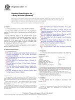
FIG. 1 Typical Installation for Externally Referenced Settlement Platform
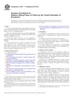
6.6 For installations where an internal reference or benchmark supported on unyielding soil or rock beneath the compressible layer(s) of interest is used, rigid metal pipe similar to
that described in 6.3 above is recommended. Alternatively, an
anchor is used in conjunction with metal pipe to ensure a fixed
base reference point. A typical anchor may consist of a number
of metal prongs which are driven from an initially retracted
punching failure might occur as a result of the down-drag load
applied to the riser-pipe.
6.5 Surface Protection Monument—for settlement platforms
that remain in place following completion of construction,
installation of a surface protection monument to protect the
riser pipe from tampering is advisable. Design of a protective
casing system as described in Practice D5092 is recommended.
3
D6598 − 11
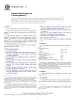
FIG. 2 Typical Installation for Internally Referenced Settlement Platform with Grouted Pipe
position through slots in the conical drive point of an outer
metal pipe using an inner metal riser pipe.
reflect these alternative configurations as well as a number of
other features such as the use of riser pipe isolation casing.
7. Procedure
7.2 Assuming that either the fill level is at the elevation that
the base platform is to be installed or an excavation has been
made to permit the level of interest to be accessed, installation
of the base platform is preceded by the placement of a bedding
layer. Typically, a free-draining clean sand is used (see Fig. 1
for example). If that an external reference point is used, the first
7.1 A variety of instrument designs are possible depending
on the specific application for which the settlement platform is
to be used and whether an external or internal reference point
or bench mark is to be used. This standard test method
describes a number of settlement platform systems intended to
4
D6598 − 11
FIG. 3 Typical Installation for Internally Referenced Settlement Platform with Borros Anchor
placement of any fill layers with earth-moving equipment. Use
of a measurement system capable of measuring deformations
to an accuracy of 1% of the estimated total deformation is
appropriate in most cases. For cases where total deformations
are limited to the order of a few centimeters, accuracy is
limited by the practicality of making the measurements. As
filling progresses, additional sections of riser pipe are added to
maintain the top of the riser pipe above the elevation of the fill.
Sections of riser pipe between 1 and 2 m long are convenient
for assembly as well as monitoring purposes. In cases where
section of riser pipe is connected to the base platform and the
platform is positioned on the bedding sand and leveled
manually. If that an internal reference system is used, the lower
end of the shaft is first embedded in the unyielding soil stratum
(see section 7.3). Backfill is then hand placed and compacted
on top of the base platform to provide initial stability. The level
of compaction required should be established for the specific
project. Ensure that the riser pipe remains vertical during early
filling. The zero reading or initial elevation of the top of the
base plate is determined and recorded at this stage prior to the
5
D6598 − 11
recorded measurements. When extra sections of riser pipe are
being added, ensure that only the coupling at the bottom of the
section being added turns. Use two wrenches, one to hold the
new section of pipe and the other to hold the coupling or the
pipe immediately below it, depending on whether or not the
coupling was in place during the last sequence of measurements.
concerns exist about the influence of extraneous factors as
noted in section 6.4 on the recorded deformations, riser pipe
isolation casing are added as appropriate to ensure that the top
of the isolation casing remains at least 25 mm below the top of
the riser pipe and always above the top of the fill (see Fig. 1 for
example).
7.3 If an internal reference point is used, then a system
configuration such as shown in Figs. 2 and 3 should be used. A
principal difference between these systems and the externally
referenced system shown in Fig. 1 is the section of shaft or
anchor that extends below the elevation of the base platform
into the underlying unyielding layer. While externally referenced systems are used to indicate the relative vertical movement between the top of a riser pipe that is rigidly connected to
the base platform and a remote survey point, internally
referenced systems permit measurement of the relative vertical
movement between the top of an outer riser pipe. The outer
riser pipe is rigidly connected to the base platform and an inner
riser pipe that is rigidly connected to an anchoring system
founded in an underlying unyielding layer and passes through
the center of the base platform. The anchor is installed by
pre-drilling or hand-augering a hole into the competent stratum. The anchor is then placed in the hole and grouted in place
using a cement-bentonite or similar material of sufficiently low
strength to avoid supporting the platform. At contact between
the grout and the platform avoid contact that influences the
measured settlement. The unyielding layer should occur at
shallow depths below the base plate to ensure economy of the
internally referenced system relative to the cost of referencing
surveys to an external point or bench mark. The choice
between an externally or internally referenced system is based
on comparative costs – the deeper the compressible layer, the
more likely an externally referenced system is chosen.
7.5 Appropriate measures shall be implemented to maintain
the alignment of the riser and the riser pipe isolation casing in
a vertical position during the period that data is be collected.
Construction equipment must be operated in a manner to
ensure that the settlement platforms are not damaged or
displaced laterally. Each assembly shall be clearly marked and
flagged with ground stakes or protective barricades, if appropriate.
7.6 Although settlement platforms are generally used for
relatively short-term applications, there may be some cases
where long-term performance is a consideration. Issues such as
their performance over extended periods of time as well as
corrosion of the components should be appropriately considered. For cases where factors such as backfill materials and
methods, down-drag, isolation casing alternatives or effects of
the instrument on load distributions are likely to impact the
precision of the recorded measurements, appropriate procedures are identified on a case by case basis.
7.7 The number and spacing of settlement platforms is
project dependent and therefore no specific guidelines are
presented in this standard.
8. Report
8.1 For settlement platform measurements, report the following information:
8.1.1 Settlement platform identification and initial elevation
8.1.2 Reference point type
8.1.3 Elevation of the reference point
8.1.4 Description of measuring device(s) used
7.4 Readings of the elevation of the top of the riser pipe are
taken at time intervals frequent enough to permit critical
deformations to be recorded. In addition, readings are taken
immediately before and after any action such as the addition of
extra sections of riser pipe. These measurements, as well as an
independent measurement of the length of the section of pipe
being added, permit appropriate corrections to be made to the
9. Keywords
9.1 monitoring fill placement; field instrumentation; settlement platforms ; vertical settlement
SUMMARY OF CHANGES
Committee D18 has identified the location of selected changes to this guide since the last issue, D6598–07,
that may impact the use of this guide. (Approved November 1, 2011)
(1) Added units statement to the Scope.
(2) Revised Terminology to include reference to Terminology
D653.
6
D6598 − 11
ASTM International takes no position respecting the validity of any patent rights asserted in connection with any item mentioned
in this standard. Users of this standard are expressly advised that determination of the validity of any such patent rights, and the risk
of infringement of such rights, are entirely their own responsibility.
This standard is subject to revision at any time by the responsible technical committee and must be reviewed every five years and
if not revised, either reapproved or withdrawn. Your comments are invited either for revision of this standard or for additional standards
and should be addressed to ASTM International Headquarters. Your comments will receive careful consideration at a meeting of the
responsible technical committee, which you may attend. If you feel that your comments have not received a fair hearing you should
make your views known to the ASTM Committee on Standards, at the address shown below.
This standard is copyrighted by ASTM International, 100 Barr Harbor Drive, PO Box C700, West Conshohocken, PA 19428-2959,
United States. Individual reprints (single or multiple copies) of this standard may be obtained by contacting ASTM at the above
address or at 610-832-9585 (phone), 610-832-9555 (fax), or (e-mail); or through the ASTM website
(www.astm.org). Permission rights to photocopy the standard may also be secured from the Copyright Clearance Center, 222
Rosewood Drive, Danvers, MA 01923, Tel: (978) 646-2600; />
7