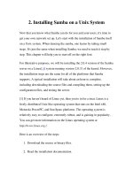
A computer system consists of hardware, system programs, and application programs figs 1
Bạn đang xem bản rút gọn của tài liệu. Xem và tải ngay bản đầy đủ của tài liệu tại đây (421.81 KB, 30 trang )
1
INTRODUCTION
1.1 WHAT IS AN OPERATING SYSTEM?
1.2 HISTORY OF OPERATING SYSTEMS
1.3 THE OPERATING SYSTEM ZOO
1.4 COMPUTER HARDWARE REVIEW
1.5 OPERATING SYSTEM CONCEPTS
1.6 SYSTEM CALLS
1.7 OPERATING SYSTEM STRUCTURE
1.8 RESEARCH ON OPERATING SYSTEMS
1.9 OUTLINE OF THE REST OF THIS BOOK
1.10 METRIC UNITS
1.11 SUMMARY
Banking
system
Airline
reservation
Operating system
Web
browser
Compilers Editors
Application programs
Hardware
System
programs
Command
interpreter
Machine language
Microarchitecture
Physical devices
Fig. 1-1. A computer system consists of hardware, system pro-
grams, and application programs.
1401 7094 1401
(a) (b) (c) (d) (e) (f)
Card
reader
Tape
drive
Input
tape
Output
tape
System
tape
Printer
Fig. 1-2. An early batch system. (a) Programmers bring cards to
1401. (b) 1401 reads batch of jobs onto tape. (c) Operator carries
input tape to 7094. (d) 7094 does computing. (e) Operator carries
output tape to 1401. (f) 1401 prints output.
$JOB, 10,6610802, MARVIN TANENBAUM
$FORTRAN
$LOAD
$RUN
$END
Fortran program
Data for program
Fig. 1-3. Structure of a typical FMS job.
Job 3
Job 2
Job 1
Operating
system
Memory
partitions
Fig. 1-4. A multiprogramming system with three jobs in memory.
Monitor
Keyboard
Floppy
disk drive
Hard
disk drive
Hard
disk
controller
Floppy
disk
controller
Keyboard
controller
Video
controller
MemoryCPU
Bus
Fig. 1-5. Some of the components of a simple personal computer.
Fetch
unit
Fetch
unit
Fetch
unit
Decode
unit
Decode
unit
Execute
unit
Execute
unit
Execute
unit
Execute
unit
Decode
unit
Holding
buffer
(a) (b)
Fig. 1-6. (a) A three-stage pipeline. (b) A superscalar CPU.
Registers
Cache
Main memory
Magnetic tape
Magnetic disk
1 nsec
2 nsec
10 nsec
10 msec
100 sec
<1 KB
1 MB
64-512 MB
5-50 GB
20-100 GB
Typical capacityTypical access time
Fig. 1-7. A typical memory hierarchy. The numbers are very rough
approximations.
Surface 2
Surface 1
Surface 0
Read/write head (1 per surface)
Direction of arm motion
Surface 3
Surface 5
Surface 4
Surface 7
Surface 6
Fig. 1-8. Structure of a disk drive.
User program
and data
User program
and data
Operating
System
Address
0xFFFFFFFF
Limit
Base
0
(a)
User-2 data
User-1 data
User program
Operating
System
Base-2
Limit-2
Limit-2
Limit-1
Base-2
Base-1
(b)
Limit-1
Base-1
Registers
when
program 1
is running
Registers
when
program 2
is running
Fig. 1-9. (a) Use of one base-limit pair. The program can access
memory between the base and the limit. (b) Use of two base-limit
pairs. The program code is between Base-1 and Limit-1 whereas
the data are between Base-2 and Limit-2.
CPU
Interrupt
controller
Disk
controller
Disk drive
Current instruction
Next instruction
1. Interrupt
3. Return
2. Dispatch
to handler
Interrupt handler
(b)(a)
1
3
42
Fig. 1-10. (a) The steps in starting an I/O device and getting an
interrupt. (b) Interrupt processing involves taking the interrupt,
running the interrupt handler, and returning to the user program.
ISA
bridge
Modem
Mouse
PCI
bridge
CPU
Main
memory
SCSI USB
Local bus
Sound
card
Printer
Available
ISA slot
ISA bus
IDE
disk
Available
PCI slot
Key-
board
Mon-
itor
Graphics
adaptor
Level 2
cache
Cache bus Memory bus
PCI bus
Fig. 1-11. The structure of a large Pentium system
A
B
D E F
C
Fig. 1-12. A process tree. Process A created two child processes, B
and C. Process B created three child processes, D, E, and F.
(a) (b)
Fig. 1-13. (a) A potential deadlock. (b) An actual deadlock.
Root directory
Students Faculty
Leo Prof.Brown
Files
Courses
CS101 CS105
Papers Grants
SOSP COST-11
Committees
Prof.Green Prof.WhiteMattyRobbert
Fig. 1-14. A file system for a university department.
Root Floppy
ab
cd cd
abxy
xy
(a) (b)
Fig. 1-15. (a) Before mounting, the files on drive 0 are not accessi-
ble. (b) After mounting, they are part of the file hierarchy.
Process
Pipe
Process
AB
Fig. 1-16. Two processes connected by a pipe.
Return to caller
4
10
6
0
9
78
3
2
1
11
Dispatch
Sys call
handler
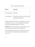
Address
0xFFFFFFFF
User space
Kernel space
(Operating system)
Library
procedure
read
User program
calling read
Trap to the kernel
Put code for read in register
Increment SP
Call read
Push fd
Push &buffer
Push nbytes
5
Fig. 1-17. The 11 steps in making the system call
read(fd, buffer, nbytes).
Process management
Call Description
pid = fork( ) Create a child process identical to the parent
pid = waitpid(pid, &statloc, options) Wait for a child to terminate
s = execve(name, argv, environp) Replace a process’ core image
exit(status) Terminate process execution and return status
File management
Call Description
fd = open(file, how, ) Open a file for reading, writing or both
s = close(fd) Close an open file
n = read(fd, buffer, nbytes) Read data from a file into a buffer
n = write(fd, buffer, nbytes) Write data from a buffer into a file
position = lseek(fd, offset, whence) Move the file pointer
s = stat(name, &buf) Get a file’s status information
Directory and file system management
Call Description
s = mkdir(name, mode) Create a new directory
s = rmdir(name) Remove an empty directory
s = link(name1, name2) Create a new entry, name2, pointing to name1
s = unlink(name) Remove a directory entry
s = mount(special, name, flag) Mount a file system
s = umount(special) Unmount a file system
Miscellaneous
Call Description
s = chdir(dirname) Change the working directory
s = chmod(name, mode) Change a file’s protection bits
s = kill(pid, signal) Send a signal to a process
seconds = time(&seconds) Get the elapsed time since Jan. 1, 1970
Fig. 1-18. Some of the major POSIX system calls. The return code
s is −1 if an error has occurred. The return codes are as follows:
pid is a process id, fd is a file descriptor, n is a byte count, position
is an offset within the file, and seconds is the elapsed time. The
parameters are explained in the text.
#define TRUE 1
while (TRUE) { /
*
repeat forever
*
/
type prompt( ); /
*
display prompt on the screen
*
/
read command(command, parameters); /
*
read input from terminal
*
/
if (fork( ) != 0) { /
*
fork off child process
*
/
/
*
Parent code.
*
/
waitpid(−1, &status, 0); /
*
wait for child to exit
*
/
} else {
/
*
Child code.
*
/
execve(command, parameters, 0); /
*
execute command
*
/
}
}
Fig. 1-19. A stripped-down shell. Throughout this book, TRUE is
assumed to be defined as 1.
Address (hex)
FFFF
0000
Stack
Data
Text
Gap
Fig. 1-20. Processes have three segments: text, data, and stack.
/usr/ast /usr/jim
16
81
40
games
test
(a)
31
70
59
38
bin
memo
f.c.
prog1
/usr/ast /usr/jim
16
81
40
70
games
test
note
(b)
31
70
59
38
bin
memo
f.c.
prog1
Fig. 1-21. (a) Two directories before linking /usr/jim/memo to
ast’s directory. (b) The same directories after linking.
(a) (b)
bin dev lib mnt usr
bin dev usr
lib
Fig. 1-22. (a) File system before the mount. (b) File system after
the mount.
UNIX Win32 Description
fork CreateProcess Create a new process
waitpid WaitForSingleObject Can wait for a process to exit
execve (none) CreateProcess = fork + execve
exit ExitProcess Terminate execution
open CreateFile Create a file or open an existing file
close CloseHandle Close a file
read ReadFile Read data from a file
write WriteFile Write data to a file
lseek SetFilePointer Move the file pointer
stat GetFileAttributesEx Get various file attributes
mkdir CreateDirectory Create a new directory
rmdir RemoveDirectory Remove an empty directory
link (none) Win32 does not support links
unlink DeleteFile Destroy an existing file
mount (none) Win32 does not support mount
umount (none) Win32 does not support mount
chdir SetCurrentDirectory Change the current working directory
chmod (none) Win32 does not support security (although NT does)
kill (none) Win32 does not support signals
time GetLocalTime Get the current time
Fig. 1-23. The Win32 API calls that roughly correspond to the
UNIX calls of Fig. 1-18.
Main
procedure
Service
procedures
Utility
procedures
Fig. 1-24. A simple structuring model for a monolithic system.