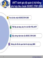
Tiêu chuẩn iso 05673 2 2005
Bạn đang xem bản rút gọn của tài liệu. Xem và tải ngay bản đầy đủ của tài liệu tại đây (241.63 KB, 18 trang )
INTERNATIONAL
STANDARD
ISO
5673-2
First edition
2005-02-15
Agricultural tractors and machinery —
Power take-off drive shafts and powerinput connection —
Part 2:
Specification for use of PTO drive shafts,
and position and clearance of PTO drive
line and PIC for various attachments
Tracteurs et matériels agricoles — Arbres de transmission à cardans de
prise de force et arbre récepteur de la machine —
--`,,,```-`-`,,`,,`,`,,`---
Partie 2: Spécifications relatives à l'utilisation des arbres de
transmission à cardans de prise de force, et position et dégagement de
la ligne de transmission de prise de force et de l'arbre récepteur de la
machine pour différents systèmes d'attelage
Reference number
ISO 5673-2:2005(E)
Copyright International Organization for Standardization
Reproduced by IHS under license with ISO
No reproduction or networking permitted without license from IHS
© ISO 2005
Not for Resale
ISO 5673-2:2005(E)
PDF disclaimer
This PDF file may contain embedded typefaces. In accordance with Adobe's licensing policy, this file may be printed or viewed but
shall not be edited unless the typefaces which are embedded are licensed to and installed on the computer performing the editing. In
downloading this file, parties accept therein the responsibility of not infringing Adobe's licensing policy. The ISO Central Secretariat
accepts no liability in this area.
Adobe is a trademark of Adobe Systems Incorporated.
Details of the software products used to create this PDF file can be found in the General Info relative to the file; the PDF-creation
parameters were optimized for printing. Every care has been taken to ensure that the file is suitable for use by ISO member bodies. In
the unlikely event that a problem relating to it is found, please inform the Central Secretariat at the address given below.
--`,,,```-`-`,,`,,`,`,,`---
© ISO 2005
All rights reserved. Unless otherwise specified, no part of this publication may be reproduced or utilized in any form or by any means,
electronic or mechanical, including photocopying and microfilm, without permission in writing from either ISO at the address below or
ISO's member body in the country of the requester.
ISO copyright office
Case postale 56 • CH-1211 Geneva 20
Tel. + 41 22 749 01 11
Fax + 41 22 749 09 47
Web www.iso.org
Published in Switzerland
ii
Copyright International Organization for Standardization
Reproduced by IHS under license with ISO
No reproduction or networking permitted without license from IHS
© ISO 2005 – All rights reserved
Not for Resale
ISO 5673-2:2005(E)
Contents
Page
Foreword ............................................................................................................................................................ iv
1
Scope...................................................................................................................................................... 1
2
Normative references ........................................................................................................................... 1
3
Terms and definitions........................................................................................................................... 2
4
Application and use of PTO drive shafts............................................................................................ 2
5
Position and clearance of PIC for various attachments ................................................................... 4
iii
© ISO 2005 – All rights reserved
--`,,,```-`-`,,`,,`,`,,`---
Copyright International Organization for Standardization
Reproduced by IHS under license with ISO
No reproduction or networking permitted without license from IHS
Not for Resale
ISO 5673-2:2005(E)
--`,,,```-`-`,,`,,`,`,,`---
Foreword
ISO (the International Organization for Standardization) is a worldwide federation of national standards bodies
(ISO member bodies). The work of preparing International Standards is normally carried out through ISO
technical committees. Each member body interested in a subject for which a technical committee has been
established has the right to be represented on that committee. International organizations, governmental and
non-governmental, in liaison with ISO, also take part in the work. ISO collaborates closely with the
International Electrotechnical Commission (IEC) on all matters of electrotechnical standardization.
International Standards are drafted in accordance with the rules given in the ISO/IEC Directives, Part 2.
The main task of technical committees is to prepare International Standards. Draft International Standards
adopted by the technical committees are circulated to the member bodies for voting. Publication as an
International Standard requires approval by at least 75 % of the member bodies casting a vote.
Attention is drawn to the possibility that some of the elements of this document may be the subject of patent
rights. ISO shall not be held responsible for identifying any or all such patent rights.
ISO 5673-2 was prepared by Technical Committee ISO/TC 23, Tractors and machinery for agriculture and
forestry, Subcommittee SC 4, Tractors.
This first edition of ISO 5673-2, together with ISO 5673-1, cancels and replaces ISO 5673:1993, of which it
constitutes a technical revision.
ISO 5673 consists of the following parts, under the general title Agricultural tractors and machinery — Power
take-off drive shafts and power-input connection:
Part 1: General manufacturing and safety requirements
Part 2: Specification for use of PTO drive shafts, and position and clearance of PTO drive line and PIC for
various attachments
iv
Copyright International Organization for Standardization
Reproduced by IHS under license with ISO
No reproduction or networking permitted without license from IHS
© ISO 2005 – All rights reserved
Not for Resale
INTERNATIONAL STANDARD
ISO 5673-2:2005(E)
Agricultural tractors and machinery — Power take-off drive
shafts and power-input connection —
1
--`,,,```-`-`,,`,,`,`,,`---
Part 2:
Specification for use of PTO drive shafts, and position and
clearance of PTO drive line and PIC for various attachments
Scope
This part of ISO 5673 gives the forms and applications of power take-off (PTO) drive shafts for tractors and
self-propelled machines used in agriculture, and specifies the dimensions for, and clearance zone around, the
implement power-input connection (PIC) for a variety of attachments. Its intent is to ensure proper clearance
between the PTO drive line and adjacent components on the implement and tractor when both implement and
tractor have compatible power levels. It is not intended as a complete guide for drive-line design and does not,
for example, contain information on preventing drive-line vibration or sizing a torque limiting device. It is not
applicable to combinations of implements with tractors having high ground clearance, such as those working
in standing vegetable crops or sugar cane, nor to agricultural tractors designed for low ground clearance, such
as for lawn mowing or ground care, which require a low centre of gravity; neither is it applicable to implements
non-symmetrical in design by necessity due to their function.
2
Normative references
The following referenced documents are indispensable for the application of this document. For dated
references, only the edition cited applies. For undated references, the latest edition of the referenced
document (including any amendments) applies.
ISO 500-3:2004, Agricultural tractors — Rear-mounted power take-off types 1, 2 and 3 — Part 3: Main PTO
dimensions and spline dimensions, location of PTO
ISO 730-1:1994, Agricultural wheeled tractors — Rear-mounted three-point linkage — Part 1: Categories 1, 2,
3 and 4
ISO 6489-1:2001, Agricultural vehicles — Mechanical connections between towed and towing vehicles —
Part 1: Dimensions of hitch-hooks
ISO 6489-2:2002, Agricultural vehicles — Mechanical connections between towed and towing vehicles —
Part 2: Specifications for clevis coupling 40
ISO 6489-3:2004, Agricultural vehicles — Mechanical connections between towed and towing vehicles —
Part 3: Tractor drawbar
ISO 6489-4:2004, Agricultural vehicles — Mechanical connections between towed and towing vehicles —
Part 4: Dimensions of piton-type coupling
1
© ISO 2005 – All rights reserved
Copyright International Organization for Standardization
Reproduced by IHS under license with ISO
No reproduction or networking permitted without license from IHS
Not for Resale
ISO 5673-2:2005(E)
ISO 24347, Agricultural vehicles — Mechanical connections between towed and towing vehicles —
Dimensions of ball-type coupling device (80 mm)1)
3
Terms and definitions
For the purposes of this document, the terms and definitions given in ISO 5673-1 apply.
4
4.1
Application and use of PTO drive shafts
Form A
A PTO drive shaft of form A with two universal joints, as shown in Figure 1, compensates for variations in
angle and length of the connecting shafts between PTO and PIC. Equal angles in W- and Z-bends will ensure
uniform transmission of rotary motion.
--`,,,```-`-`,,`,,`,`,,`---
Figure 1 — PTO drive shaft — Form A
1)
To be published.
2
Copyright International Organization for Standardization
Reproduced by IHS under license with ISO
No reproduction or networking permitted without license from IHS
© ISO 2005 – All rights reserved
Not for Resale
ISO 5673-2:2005(E)
4.2
Form B
A PTO drive shaft of form B with one wide-angle constant velocity universal joint and one universal joint, as
shown in Figure 2, compensates for variations in angle and length of the connecting shafts between PTO and
PIC. Rotary motions will be transmitted uniformly, as long as the single joint is aligned straight or at an angle
below 10°.
Figure 2 — PTO drive shaft — Form B
4.3
Form C
A PTO drive shaft of form C with two wide-angle constant velocity universal joints, as shown in Figure 3,
compensates for variations in angle and length of the connecting shafts between PTO and PIC. Rotary
motions is transmitted uniformly, even if different, or spatial bend angles are found.
Figure 3 — PTO drive shaft — Form C
3
--`,,,```-`-`,,`,,`,`,,`---
© ISO 2005 – All rights reserved
Copyright International Organization for Standardization
Reproduced by IHS under license with ISO
No reproduction or networking permitted without license from IHS
Not for Resale
ISO 5673-2:2005(E)
--`,,,```-`-`,,`,,`,`,,`---
4.4
PTO drive shaft length
The length of the PTO drive shaft shall be chosen with regard to the maximum extended and minimum closed
lengths that are expected during operation and manoeuvring.
4.5
Equal angle hitch
On a tractor implementing drive-line geometry, there shall be an equal distance from the tractor PTO to the
drawbar pin and from the drawbar pin to the PIC.
5
5.1
Position and clearance of PIC for various attachments
General
The horizontal and vertical spacing of the implement PIC shall be as shown in Figures 4 to 11 and in
accordance with Tables 1 to 8. To determine these dimensions, the tractor PTO shall be in the position
specified in ISO 500-3.
Easy access to maintain the PTO drive shaft, e.g. greasing, shall be possible.
The extreme values of PIC location and clearance zone for each category according to Tables 1 to 8 shall not
be used at the same time.
4
Copyright International Organization for Standardization
Reproduced by IHS under license with ISO
No reproduction or networking permitted without license from IHS
© ISO 2005 – All rights reserved
Not for Resale
ISO 5673-2:2005(E)
5.2
Drawbar attachment
5.2.1
Position of PIC
To determine these dimensions, the drawbar attachment shall be in the positions specified in ISO 6489-3. The
axis of the tractor PTO and PIC shall be aligned on the same vertical plane.
See Figure 4 and Table 1.
Key
1
PIC
Figure 4 — Drawbar attachment
Table 1 — Horizontal and vertical distances for drawbar attachment
Required PTO
power
Hitch
category a
kW
--`,,,```-`-`,,`,,`,`,,`---
a
Angle hitch not equal b
Equal angle hitch
h1 min h1 max a1 max l1 ±10 w1
w2 h2 min h2 max a1 max
mm
mm
mm
mm
°
°
up to 28
0
200
250
25
400
0
0
up to 48
1
220
350
25
400
0
0
up to 115
2
250
350
25
400
0
0
up to 185
3
260
350
25
500
0
0
up to 275
4
280
400
25
500
0
0
up to 400
5
310
450
25
500
0
0
l2 maxc
w1 c w2 c
mm
mm
mm
mm
°
°
b
700
100
1 000
30
5
See ISO 6489-3.
b
In order to provide clearance between the drive line and the drawbar clevis, for l2 greater than l1 the PIC distance above the
drawbar shall increase at 5° min. angle from the position l1 and h1.
c
To prevent excessive vibration in the drive line, wide-angle universal joints may be required, or the PIC shaft may need to be
angled to be in line with the PTO drive shaft.
5
© ISO 2005 – All rights reserved
Copyright International Organization for Standardization
Reproduced by IHS under license with ISO
No reproduction or networking permitted without license from IHS
Not for Resale
ISO 5673-2:2005(E)
5.2.2
PTO drive-line clearance at PIC
See Figure 5 and Table 2.
--`,,,```-`-`,,`,,`,`,,`---
Key
1
2
3
PIC
side view
top view
Figure 5 — Minimum PTO drive-line clearance envelope at PIC for drawbar attachment
Table 2 — Clearance dimensions at PIC for drawbar attachment
dmin
l2 min
l3 ± 5
l4 min
l5 min
w3 min
w4 min
w4 min b
mm
mm
mm
mm
mm
°
°
°
0
300
75
85
500
500
5
10
50
1
300
75
85
500
500
5
10
50
2
350
75
85
500
500
5
10
50
3
350
90
100
500
500
5
10
50
4
400
90
100
500
500
5
10
50
5
400
90
100
500
500
5
15
50
Hitch category a
a
See ISO 6489-3.
b
For equal angle hitch arrangement.
6
Copyright International Organization for Standardization
Reproduced by IHS under license with ISO
No reproduction or networking permitted without license from IHS
© ISO 2005 – All rights reserved
Not for Resale
ISO 5673-2:2005(E)
5.3
Three-point linkage attachment
5.3.1
Position of PIC
To determine these dimensions, the lower links of the three-point linkage shall be in accordance with
ISO 730-1.
--`,,,```-`-`,,`,,`,`,,`---
If an implement is used on a larger category hitch (e.g. a category 2 implement on a category 3 tractor hitch),
the user may need to limit the upper or lower travel of the hitch to prevent damage to the PTO drive line.
See Figure 6 and Table 3.
Key
1
PIC
Figure 6 — Three-point linkage attachment
Table 3 — Horizontal and vertical distances for three-point linkage attachment
h1
a1 max
l1
mm
mm
mm
°
°
1
100 ± 30
25
180 to 300
5
0
1
100 ± 100
25
250 to 800
5
0
2
130 ± 30
25
280 to 400
5
0
2
130 ± 100
25
350 to 900
5
0
3
130 ± 100
25
300 to 900
5
0
4
150 ± 100
25
400 to 900
5
0
Hitch categorya
a
See ISO 730-1.
7
© ISO 2005 – All rights reserved
Copyright International Organization for Standardization
Reproduced by IHS under license with ISO
No reproduction or networking permitted without license from IHS
w1 max w2
Not for Resale
ISO 5673-2:2005(E)
5.3.2
PTO drive-line clearance at PIC
See Figure 7 and Table 4.
--`,,,```-`-`,,`,,`,`,,`---
Key
1
2
3
PIC
side view
top view
Figure 7 — Minimum PTO drive-line clearance envelope at PIC for three-point linkage attachment
Table 4 —Clearance dimensions at PIC for three-point linkage attachment
Hitch category a
NOTE
dmin l2 min l3 ± 5 l4 min l5 min
w4 min
mm
mm
mm
mm
mm
°
°
1
300
75
85
500
500
45 to 15
5
2
300
75
85
500
500
45 to 15
5
3
350
90
100
500
500
45 to 15
5
4
400
90
100
500
500
45 to 15
5
For l1 see Table 3.
a
See ISO 730-1.
b
w3 = 51 – (l1/25)
8
Copyright International Organization for Standardization
Reproduced by IHS under license with ISO
No reproduction or networking permitted without license from IHS
w3 minb
© ISO 2005 – All rights reserved
Not for Resale
ISO 5673-2:2005(E)
5.4
Hitch hook/piton-fix/ball type attachment
5.4.1
Position of PIC
To determine these dimensions, the hitch hook shall be in the position specified in ISO 6489-1, ISO 6489-4
and ISO 24347.
See Figure 8 and Table 5.
Key
1
PIC
Figure 8 — Hitch hook/piton-fix/ball type attachment
Table 5 — Horizontal and vertical distances for hitch hook/piton-fix/ball type attachment
Required PTO power
h1 min
h1 max
a1 max
l1a
w1 maxa
w2 maxa
kW
mm
mm
mm
mm
°
°
u 92
250
700
100
700 to 1500
30
5
80 to 185
260
700
100
800 to 1500
30
5
150 to 350
280
700
100
900 to 1500
30
5
a
To prevent excessive vibration in the drive line, wide-angle universal joints could be required, or the PIC shaft could need to be
angled to be in line with the PTO drive shaft.
--`,,,```-`-`,,`,,`,`,,`---
9
© ISO 2005 – All rights reserved
Copyright International Organization for Standardization
Reproduced by IHS under license with ISO
No reproduction or networking permitted without license from IHS
Not for Resale
ISO 5673-2:2005(E)
5.4.2
PTO drive-line clearance at PIC
See Figure 9 and Table 6.
Key
1
PIC
2
side view
3
top view
Figure 9 — Minimum PTO drive-line clearance envelope at PIC for hitch hook/piton-fix/ball type
attachment
Table 6 — Clearance dimensions at PIC for hitch hook/piton-fix/ball type attachment
Required PTO power dmin l2 min l3 ±5 l4 min l5 min w3 min
kW
mm
mm
mm
mm
mm
°
u 92
300
75
85
700
785
5
80 to 185
350
90
100
800
900
5
150 to 350
400
90
100
900
1 000
5
--`,,,```-`-`,,`,,`,`,,`---
10 Organization for Standardization
Copyright International
Reproduced by IHS under license with ISO
No reproduction or networking permitted without license from IHS
© ISO 2005 – All rights reserved
Not for Resale
ISO 5673-2:2005(E)
5.5
Clevis-type attachment
5.5.1
Position of PIC
To determine these dimensions, the clevis shall be in the position specified in ISO 6489-2.
See Figure 10 and Table 7.
Key
1
PIC
Figure 10 — Clevis-type attachment
Table 7 — Horizontal and vertical distances for clevis-type attachment
a
w1 maxa w2 maxa
kW
mm
mm
mm
mm
°
°
u 92
250
400
100
700 to 1 500
5
5
80 to 185
260
500
100
800 to 1 500
5
5
150 to 350
280
500
100
900 to 1 500
5
5
To prevent excessive vibration, wide-angle universal joints could be required.
11
© ISO 2005 – All rights reserved
Copyright International Organization for Standardization
Reproduced by IHS under license with ISO
No reproduction or networking permitted without license from IHS
l1a
--`,,,```-`-`,,`,,`,`,,`---
Required PTO power h1 min h1 max a1 max
Not for Resale
ISO 5673-2:2005(E)
5.5.2
PTO drive-line clearance at PIC
See Figure 11 and Table 8.
Key
1
2
3
PIC
side view
top view
Figure 11 — Minimum PTO drive-line clearance envelope at PIC for clevis-type attachment
Table 8 — Clearance dimensions at PIC for clevis-type attachment
Required PTO power dmin l2 min l3 ±5 l4 min l5 min w3 min
12
Copyright International Organization for Standardization
Reproduced by IHS under license with ISO
No reproduction or networking permitted without license from IHS
kW
mm
mm
mm
mm
mm
°
u 92
300
75
85
700
785
5
80 to 185
350
90
100
800
900
5
150 to 350
400
90
100
900
1 000
5
--`,,,```-`-`,,`,,`,`,,`---
© ISO 2005 – All rights reserved
Not for Resale
--`,,,```-`-`,,`,,`,`,,`---
Copyright International Organization for Standardization
Reproduced by IHS under license with ISO
No reproduction or networking permitted without license from IHS
Not for Resale
--`,,,```-`-`,,`,,`,`,,`---
ISO 5673-2:2005(E)
ICS 65.060.01
Price based on 12 pages
© ISO 2005 – All rights reserved
Copyright International Organization for Standardization
Reproduced by IHS under license with ISO
No reproduction or networking permitted without license from IHS
Not for Resale