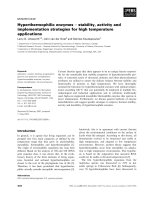
a metallization and bonding approach for high performance carbon nanotube thermal interface materials
Bạn đang xem bản rút gọn của tài liệu. Xem và tải ngay bản đầy đủ của tài liệu tại đây (983.09 KB, 9 trang )
A metallization and bonding approach for high performance carbon nanotube thermal
interface materials
This article has been downloaded from IOPscience. Please scroll down to see the full text article.
2010 Nanotechnology 21 445705
( />Download details:
IP Address: 128.211.166.51
The article was downloaded on 06/11/2012 at 14:31
Please note that terms and conditions apply.
View the table of contents for this issue, or go to the journal homepage for more
Home Search Collections Journals About Contact us My IOPscience
IOP PUBLISHING NANOTECHNOLOGY
Nanotechnology 21 (2010) 445705 (8pp) doi:10.1088/0957-4484/21/44/445705
A metallization and bonding approach for
high performance carbon nanotube
thermal interface materials
Robert Cross
1
, Baratunde A Cola
2
, Timothy Fisher
2
,XianfanXu
2
,
Ken Gall
3
and Samuel Graham
1,3
1
George W Woodruff School of Mechanical Engineering, Georgia Institute of Technology,
771 Ferst Drive, Atlanta, GA 30332, USA
2
Birck Nanotechnology Center, Purdue University, 1205 W State Street, West Lafayette,
IN 47907, USA
3
School of Materials Science and Engineering, Georgia Institute of Technology,
771 Ferst Drive, Atlanta, GA 30332, USA
E-mail:
Received 17 March 2010, in final form 26 August 2010
Published 8 October 2010
Online at stacks.iop.org/Nano/21/445705
Abstract
A method has been developed to create vertically aligned carbon nanotube (VACNT) thermal
interface materials that can be attached to a variety of metallized surfaces. VACNT films were
grown on Si substrates using standard CVD processing followed by metallization using Ti/Au.
The coated CNTs were then bonded to metallized substrates at 220
◦
C. By reducing the
adhesion of the VACNTs to the growth substrate during synthesis, the CNTs can be completely
transferred from the Si growth substrate and used as a die attachment material for electronic
components. Thermal resistance measurements using a photoacoustic technique showed
thermal resistances as low as 1
.7mm
2
KW
−1
for bonded VACNT films 25–30 µm in length
and10mm
2
KW
−1
forCNTsupto130µm in length. Tensile testing demonstrated a die
attachment strength of 40 N cm
−2
at room temperature. Overall, these metallized and bonded
VACNT films demonstrate properties which are promising for next-generation thermal interface
material applications.
(Some figures in this article are in colour only in the electronic version)
1. Introduction
Considerable attention has been focused on developing
advanced thermal interface materials (TIMs) that utilize the
extraordinarily high axial thermal conductivity of carbon
nanotubes (CNTs). For CNTs, theoretical predictions suggest
thermal conductivity values as high as 3000 W m
−1
K
−1
[1]and
6600 W m
−1
K
−1
[2] for individual multi-wall and single-wall
CNTs, respectively. Compared to the thermal conductivity of
state-of-the-art thermal interface materials, the axial thermal
conductivity of CNTs is at least two orders of magnitude
greater. However, the development of carbon-nanotube-based
TIMs have yet to produce films which are close to the high
thermal conductivity found in individual nanotubes. Early
studies focused on dispersing CNTs in a compliant polymer
matrix to enhance the effective thermal conductivity of the
composite structures [3]. Yet, only modest improvements
in thermal performance over neat polymers were achieved.
This was a result of the large thermal resistances which exist
between CNTs and polymer matrices as well as the reduction
in phonon velocities in the CNTs caused by interactions with
the polymer matrix [4]. More recently, significant attention
has shifted to vertically aligned CNT (VACNT) arrays in the
form of films and mats. In contrast to the polymer–CNT
composites, the VACNT arrays are promising TIM structures
that have demonstrated thermal properties that compare
favorably to state-of-the-art TIM materials [5]. VACNT
films possess a synergistic combination of high mechanical
compliance and high effective thermal conductivity—in the
range of 10–200 W m
−1
K
−1
[6–8]. The compliance of these
films is particularly advantageous in addressing mismatches
in coefficients of thermal expansion that can cause TIM
0957-4484/10/445705+08$30.00 © 2010 IOP Publishing Ltd Printed in the UK & the USA1
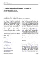
Nanotechnology 21 (2010) 445705 RCrosset al
Figure 1. (a) Schematic (not to scale) of an interface with the addition of a vertically oriented CNT array of thickness t
array
[5]. (b) Buckled
CNT contacting an opposing surface with its wall. As shown, some CNTs do not make direct contact with the opposing surface.
(c) Resistance schematic of a one-sided CNT array interface between two substrates, showing constriction resistances (
R
csi
), phonon ballistic
resistances (
R
bi
) and the effective resistance of the CNT array (R
array
).
delamination and device failure. Also, in contrast to polymer–
CNT composites and the best thermal greases, CNT array
interfaces are dry and chemically stable in air from cryogenic
to high temperatures (
∼450
◦
C), making them suitable for
extreme-environment applications [9].
The most actively studied CNT array interface structure
is the ‘one-sided’ CNT array interface that consists of CNTs
directly grown on one substrate with the free ends of the
CNTs in contact with an opposing substrate (see figure 1).
The numerous CNT contacts at both the growth and opposing
substrates form parallel heat flow paths within the framework
of the thermal resistance network. The resistance at each local
CNT–substrate contact can be modeled as two resistances in
series [10]: (1) a classical substrate constriction resistance
(
R
cs
)and(2)aresistance(R
b
) that results from the ballistic
nature of phonon transport through contacts much smaller
than the phonon mean free path in the materials (
∼100 nm).
The remaining resistance (
R
array
) is from heat conduction
through the CNT array. This effective resistance is defined for
the entire array (including void spaces). Based on previous
measurements, when the array height is less than 50
µm, R
array
is usually negligible in comparison to the resistances at the
CNT–substrate contacts [10]. Thus, the development of high
performance thermal interface materials based on VACNTs
requires the reduction in contact resistance between CNTs and
their mating substrates. Overall, it has been observed that the
larger of the two contact resistances exists between the free
ends of the CNTs and the opposing substrate when compared
to the contact between CNTs and the growth substrate.
The thermal resistance between the opposing substrate and
the CNT free ends has been reduced through the application
of pressure across the CNT interface. The use of a pressure
contact results in increased contact area, providing more
parallel pathways for heat to flow into the CNT array.
Thus, such contacts heavily depend on the deformation and
contact mechanics at the interface. Typical specific thermal
resistances, which are normalized based on contact area
for these TIMs, lie in the range of 7–20 mm
2
KW
−1
for
contact with surfaces such as Ag, Cu, Ni and Al (table 1).
Alternatively, metallization using indium has also been utilized
to bond the CNTs to a second substrate, resulting in improved
interface resistance without the need for pressure. Resistances
for this type of metallization have reached values close to
1mm
2
KW
−1
, showing the importance of addressing the
contact resistance at the CNT–substrate interface (table 1).
Overall, the use of metallization is a promising processing step
that may enable the VACNTs to act as a die attachment layer.
However, the long term stability issues surrounding the use
of indium and other low melting point solder metallizations
can limit the application of these TIMs due to degradation
of the metallization. Moreover, the mechanical strength of
these interfaces has not been tested to determine if they will
be sufficient for die attachment. Beyond considerations for
metallization, it should be noted that the single-sided CNT
interface structure requires synthesis on substrates at elevated
temperatures. Due to the high processing temperatures and
the potential incompatibility of the catalyst with the growth
substrate, this architecture puts limitations on the materials
which can be utilized in making VACNT-based TIMs.
In this paper, we explore the use of metallization and
bonding of VACNT films for the creation of thermal interface
and die attachment materials. The metallization is based
on evaporated titanium and gold layers, which are used to
bond CNT interfaces at temperatures typical of solder reflow
cycles. To circumvent the problems of synthesizing VACNTs
on sensitive substrates, a combination of transfer printing and
thermocompression bonding [19, 20] was used to transfer
CNTs from their growth substrates to bulk copper and Si
substrates. Copper and Si were used to represent heat sinks
and temperature-sensitive electronic components, which are
involved in electronics packaging. Thermal resistance of the
entire array was explored using a photoacoustic method [14]
while die attachment strength was measured through tensile
testing.
2
Nanotechnology 21 (2010) 445705 RCrosset al
Table 1. Thermal resistances of one-sided CNT array TIMs.
Interface
Array
height
(
µm)
Number
density
(CNTs
µm
−2
)
CNT
diameter
(nm)
Pressure
(kPa)
Resistance
(mm
2
KW
−1
)
Dry contacts
Si–CNT–Ag [11] 25 100–1000 20–60 350 7
.0 ± 0.5
Si–CNT–Cu [12] 13 30 15–50 450 19
± 5
Si–CNT–Ni [13] 30 10 100 550 12
± 1
Si–CNT–Ag [14] 40 100–1000 20–40 210 8
.0 ± 0.5
Si–CNT–Al [15] 10 18 10–15 150 7
± 5
Si–CNT–Ni [16] 45–55 270 — 410 8
± 1
SiC–CNT–Ag [9] 20–30 100–1000 40 69 12
± 1 (at 250
◦
C)
Free ends bonded
Si–CNT/In–Au [17] 10 100–1000 20–30 —
∼1
Si–CNT/Pd–Al [18] 28 87 000 1–2 — 12
± 1
2. Experimental procedure
2.1. CNT growth
Vertically aligned carbon nanotubes were grown using a
thermal chemical vapor deposition (CVD) process in a quartz
tube furnace. Synthesis conditions and times were varied
in order to produce CNTs, which ranged in length from
20–225
µm. For the growth of CNTs longer than 100 µmin
length, first, 100 nm of silicon dioxide was grown on 1 cm ×
1 cm silicon substrates using plasma-enhanced chemical vapor
deposition. Next, 5 nm of Fe was evaporated onto the oxidized
Si wafer to form the catalyst layer for carbon nanotube
synthesis. The CVD synthesis of the carbon nanotubes was
performed up to 5 min at 800
◦
C using a combination of argon,
hydrogen, methane and acetylene as process gases. At a
temperature of 800
◦
C, CNT array heights up to 225 µmwere
obtained during the synthesis process. To increase the adhesion
of the CNTs to the substrate, a 10 nm thick layer of Ti was
applied directly to the Si substrate without the use of SiO
2
.
Next, a 5 nm Fe layer was evaporated on top of the Ti layer
and the same growth procedure as described above was used to
synthesize the CNTs. The use of this catalyst layer reduced the
growth rate of the CNTs to approximately 6
µmmin
−1
with a
typical growth length of 30 µm after 5 min of growth. Overall,
the use of either catalyst system was found sufficient to create
one-sided CNT structures as shown in figure 1.However,the
use of the Ti/Fe catalyst layer was found to be the most robust
in terms of CNT adhesion to the growth substrate.
Since the direct synthesis of CNTs is not always possible
on temperature-sensitive devices, we investigated a method
to transfer the CNTs from their growth substrates at low
temperatures. To create VACNT thermal interface materials
through transfer printing, the adhesion of the CNTs to the
growth substrate was weakened in order to enhance the yield of
the transfer process. It has been shown that introducing water
vapor via a carrier gas after the growth phase can help to reduce
amorphous carbon within the array, etch the end caps of the
nanotubes and also etch the CNT/catalyst interface, thereby
weakening its bond to the growth substrate [21]. Thus, this
technique was implemented for the transfer printing of CNT
arrays to both Cu and Si substrates.
To introduce the water vapor, a bubbler apparatus was
attached to the growth furnace. Argon was used as the carrier
gas and the flow rate was controlled with an external mass flow
controller. The water vapor was introduced immediately after
the CNT growth phase at a furnace temperature of 800
◦
C.
This step lasted 5 min and the Ar flow rate was varied up to
160 sccm, depending on the initial CNT length. Lower flow
rates were used with shorter CNTs while higher flow rates
were found to work well with longer CNTs. After water vapor
etching, the samples were removed and transfer-printed onto
Cu or Si substrates as discussed below. In some cases, CNT
arrays were simply attached to polyimide tape after the water
vapor etch. This process provided a convenient method to store
CNT array samples for bonding at a later time and will be
discussed in section 3.
2.2. Bonding and transfer process
In order to bond the vertically aligned CNTs to an opposing
substrate, both the substrate and the free ends of the CNTs
were metallized. The metallization consisted of 50 nm of
Ti followed by 500–1000 nm of Au. This metallization
was chosen since it circumvents some of the reliability
issues associated with low melting point solders while being
amenable to low temperature processing (
<300
◦
C). The use
of bonding temperatures less than 300
◦
C ensures that the
processing is compatible with current solder reflow processing
temperature limits used in semiconductor manufacturing.
Thus, a wide range of substrates and temperature-sensitive
devices, which are also metallized, will be compatible with
this process. In general, the mechanism for the bonding across
the Au–Au interface is not a reflow process. Instead, it is a
result of Au–Au self-diffusion. This method of bonding is
generally performed in the presence of an applied external load
which has been shown to help reduce the temperature at which
the bonding occurs or to improve the bond strength at a given
temperature.
The metallized CNTs were bonded to copper and
Si substrates also coated with Ti/Au metallization layers.
Bonding was performed using a Carver benchtop hot press
at 220
◦
C. To bond one-sided interface materials, the
metallization was simply applied to the free ends of the
CNTs, which were well adhered to their growth substrate.
3
Nanotechnology 21 (2010) 445705 RCrosset al
Figure 2. Figure showing structure of samples utilized in the tensile
testing of the bonded CNT arrays.
For CNT samples that were exposed to water vapor etching,
the bonding process resulted in the complete transfer of the
CNT arrays to the Cu or Si substrate. Once transferred, a
second metallization layer was applied to the CNTs in order
to bond a second substrate, allowing the CNTs to act as a die
attachment material. While Ti/Au metallization was used in
these experiments, it is also possible to replace the Ti layer with
Ni in order to reduce or eliminate the diffusion of metals such
as Cu into the gold layer. XPS analysis of thermally annealed
samples (240
◦
C for 10 h) with 100 nm thick Ni layers between
the Ti and Au layers have revealed the effectiveness of this
diffusion barrier.
2.3. Characterization of the bonded CNT arrays
Tensile testing was utilized to determine the strength of the
bonded CNT interfaces. For these experiments, CNT arrays
1cm
× 1 cm in area with an average length of approximately
30
µm were bonded to a copper substrate utilizing the Ti/Au
metallization. An additional layer of metallization was then
applied to the free ends of the CNTs, which were then bonded
to a metallized Si chip, 1 cm
× 1 cm in size (figure 2).
The tensile tests were performed using an MTS Insight
2 electromechanical test system equipped with a 100 N load
cell and compression platens. Both sides of the sample
were attached to self-aligning platens using quick drying glue.
Once the adhesive was completely dried, the tensile test was
performed at a controlled displacement rate until fracture
occurred.
Thermal resistance measurements were performed using
a photoacoustic (PA) measurement technique that has
been reported previously [14]. The PA technique is a
noninvasive procedure that has proven successful at obtaining
thermal conductivity of thin films and thermal resistance
of interfaces [14]. In the PA technique, a laser heating
source was used to periodically irradiate the sample surface,
which was surrounded by a sealed acoustic chamber. The
acoustic response of the air in the chamber above the sample
was measured with a microphone that was embedded in the
chamber wall. The measured pressure signal was used in
conjunction with the model described in [14] to determine
thermal interface resistance. The transient nature of the PA
technique and the analysis of many heating frequencies in a
single experiment facilitates the good resolution of thermal
interface resistance (0
.5mm
2
KW
−1
) that is necessary to
measure structures with low resistance.
In these experiments, both long and short CNTs were
measured. For short CNTs, the one-sided thermal interface
structure was tested using nanotubes approximately 25–30
µm
in length (figure 3). For long CNTs approximately 130
µmin
length, the arrays were transfer-printed onto Si substrates since
the absence of the Ti layer resulted in poor adhesion to the
Si growth substrate, which compromised the PA experiments
(figure 3). A 25
µm thick silver foil (99.998%, Alfa Aesar,
Inc.) was attached to the top of each sample. The low thermal
resistance of the silver foil facilitated increased sensitivity to
interface resistance during PA measurements. The Ag film was
coated with 80 nm of titanium via electron beam deposition
and bonded to the Au-coated CNT arrays at 220
◦
C. Helium
was used as the gas medium for the measurements, as opposed
to air or nitrogen, because of its higher thermal conductivity,
thus producing the best signal-to-noise ratio.
3. Results
3.1. Synthesis results
The synthesis of the CNTs resulted in dense vertically aligned
growth as anticipated and verified through measurements
using a Hitachi 3500 scanning electron microscope (SEM).
Images revealed CNTs with an average diameter of 18 nm,
indicative of multiwall CNTs and a volume fraction of 9%.
Additional analysis of the CNTs was performed using Raman
spectroscopy using the 488 nm line of an Ar
+
laser, measuring
the ratio of the graphitic to defect peak intensities. The
G, or graphitic, peak which lies around 1580 cm
−1
is an
indicator of the structural order of the CNTs [22]. The
D or
defect peak lies around 1380 cm
−1
and is representative of the
disorder present in the CNTs. The ratio of these two peaks is
commonly used to assess the quality of CNTs. Raman analysis
of the samples showed a graphitic to defect intensity ratio
of 1.43 which indicated good structural order for the CNTs
(figure 4). Upon exposure to the water vapor etch step, the
CNT lengths were reduced, depending on the flow rate used
during the 5 min etch step. Data taken from the SEM images
showed an etch rate of 400 nm min
−1
forflowratesaslowas
80 sccm and increased up to 16
µmmin
−1
for flow rates of
160 sccm. Negligible etching was observed at Ar–H
2
Oflow
rates as low as 40 sccm. Additional Raman analysis after
the etch step showed negligible changes in the ratio of the
graphitic to defect (
G/D) peak intensities for flow rates up
to 40 sccm, maintaining a value of 1.43. Increasing the flow
rate above 40 sccm resulted in a linear reduction in the
G/D
peak with increasing flow rate. However, this ratio remained
above 1.3 for flow rates up to 160 sccm tested in this study.
These results indicate that relatively good structural order is
maintained in the CNTs after the etch step, which is desired
for maintaining high thermal conductivity in the CNT array.
To assess the effect of the water vapor etch step on the
adhesion of the CNTs to the growth surface, samples with
varying Ar–H
2
O etch flow rates but a fixed etch time (5 min)
were prepared. Polyimide tape was used to attempt to remove
the CNTs from the growth surface after etching to assess the
ease of transfer. For flow rates from 0–40 sccm, no transfer
from the Si growth substrate was observed (figure 5). For flow
rates between 40 and 80 sccm, only partial transfers were seen.
4
Nanotechnology 21 (2010) 445705 RCrosset al
Figure 3. Images showing the structure of the samples used in the PA testing. Left: sample used to measure short CNT arrays (∼30 µmin
height). Samples were directly grown on the Si substrate using Ti/Fe catalyst. Right: sample used to measure long CNTs (
∼130 µmin
height). Samples were transferred and bonded to Si substrates using Ti/Au bonding. For both samples, a 25
µm thick Ag foil was bonded to
the top of the array.
Figure 4. Data showing the ratio of the intensities of the Raman
peaks for the
G and D bands for CNT arrays as a function of
Ar–water vapor flow rate. Data show a clear decrease in the
G/D
intensity ratio with increasing etchant flow rate, indicating the
introduction of an increasing number of defects into the CNT array.
Finally, for flow rates that exceeded 80 sccm, it was found
that complete transfers could be obtained. Thus, water vapor
etching with Ar–water vapor flow rates of 80 sccm or greater
was used to create samples that required transfer printing of
the CNTs. As a result of the weak adhesion which occurred
during the etch step, complete CNT arrays could be removed
from the growth substrate simply by using polyimide tape and
stored for later use in the transfer printing and bonding process
(figure 6). While these results were found using polyimide
tape, the results were similar to those seen in the transfer
printing process.
Figure 6. Picture showing the transfer of 1 cm × 1cmVACNT
arrays to polyimide tape. The ease of transfer was aided by etching
the nanotubes using an Ar–H
2
O flow rate of 80 sccm.
Figure 7. SEM image showing the non-uniform gold coating on top
of the CNT array, forming large particles on the tops of CNTs.
3.2. Metallization and bonding
The metallization of the CNT arrays was analyzed using
optical and scanning electron microscopy as shown in figure 7.
The metallization thickness was measured during e-beam
evaporation using a quartz crystal microbalance. Thus, the
500 nm thick Au layer measured during deposition is based
Figure 5. Examples of CNT growth substrate after attempts to transfer CNTs to polyimide tape. The left sample shows complete transfer of
CNTs after an 80 sccm Ar–H
2
O etch flow rate. The middle two samples show partial transfers using 60 sccm and 50 sccm, respectively. The
right sample (d) utilized a 30 sccm flow rate and displayed no CNT transfer.
5
Nanotechnology 21 (2010) 445705 RCrosset al
Figure 8. Images showing the transfer of VACNT to metallized substrates: (top left) 200 µm long CNTs transferred to Si; (top right) 25 µm
long CNTs transferred to Si, and (bottom) 30
µm long CNTs transferred to Cu.
on assuming a continuous film whereas the SEM image
clearly shows that the metallization is discontinuous. The
metallization formed large and small clumps on many of the
tubes in the array. Since the coating is not uniform over the
CNT array, as shown in figure 7, this may indicate that any
interface bonded with this metallization could have a pressure-
dependent thermal resistance. This pressure dependence will
arise from the fact that the CNTs with thick metallization may
contact and bond at the interface prior to CNTs which have
little or no metallization. Thus, applied pressure will help to
increase the contact area at the bonded interface if all CNTs are
not attached during the initial bonding procedure. As a result,
the pressure dependence of the thermal resistance was tested in
this study.
The results of the transfer printing procedure are shown
in figure 8. In this figure, both long and short CNTs were
transferred to Si and Cu substrates. It is clear that the VACNT
arrays retain their vertical alignment, which is important for
creating interface materials. In addition, the weak interface
to the growth substrate promoted by the etch step allowed easy
removal of the growth substrate which was simply pulled off by
hand after the bonding step. The use of bonding temperatures
between 150–220
◦
C all resulted in successful transfers to these
secondary substrates, providing a low temperature processing
window for creating CNT thermal interface and die attachment
materials. However, it is not believed that melting and
Au reflow at the interface are responsible for the successful
bonding of the Au interfaces. While the use of small metal
particles has been shown to reduce the melting temperature
of Au, this phenomena typically happens for particles with
diameters less than 100 nm. Based on the metallization
particles seen in figure 7, no suppression of the melting
temperature is believed to occur during the bonding process.
However, the bonding across the interface is believed to be
aided by the rapid diffusion of Au and Cu atoms across the
interface, which can aid in the formation of bonding at low
temperatures. After transferring the CNTs to the Si or Cu
Figure 9. Image showing the attachment of an Si chip to a Cu
substrate by bonding to metallized VACNT arrays.
substrates, a second layer of Ti/Au metallization was applied to
the free ends and a second substrate was bonded to the VACNT
array. The results of this process are shown in figure 9 where
1cm
× 1 cm Si chips are attached to Cu substrates through the
use of metallized VACNT arrays.
As previously mentioned, the VACNT arrays could be
attached to polyimide tape and stored for later use. Polyimide
tape was chosen due to its compatibility with the bonding
temperatures used in the process described here. After
applying the Ti/Au metallization layer to the VACNT arrays
on the polyimide tape, the samples were placed in the Carver
hot press and bonded to metallized substrates as previously
described, resulting in a successful bond. Removal of the
polyimide tape was performed by soaking the sample in
acetone, which removed the adhesive and the polyimide
backing film. This process thus demonstrates the ability
to store, handle and process VACNT arrays from high
temperature tapes, which can be important for scaling up the
manufacturability of this process.
3.3. Mechanical and thermal characterization results
3.3.1. Mechanical test of bond strength. Mechanical testing
was performed on Si samples bonded to Cu substrates using
the metallized CNTs (figure 10). Data show very good
6
Nanotechnology 21 (2010) 445705 RCrosset al
Figure 10. Optical images of the tensile testing of 1 cm × 1cmSi
chips bonded to copper substrates using metallized CNTs (left) and
an image showing failed samples which display nearly uniform
coverage of CNTs on both surfaces (right).
Figure 11. High resolution SEM showing broken fibers embedded in
Au that were observed after tensile testing. These images indicate
that the failure occurs due to CNT fracture.
bond strengths for the low temperature bonding, with failure
occurring at loads between 35 and 40 N cm
−2
. Examination
of the failed samples clearly showed that nearly uniform
coverage of CNT layers was present on each substrate. Further
examination of the interface using a high resolution scanning
electron microscope showed clearly that some of the CNTs
embedded in the Au bond layer were broken (figure 11).
While it cannot be ruled out that CNT pull out occurred, these
images show that part of the failure mechanism is clearly CNT
fracture. Thus, the strength and density of the CNTs will limit
the overall strength of the CNT die attachment layers. Previous
reports on the strength of anodically bonded CNT interfaces
have shown strengths of the order of 4
.3Ncm
−2
[23].
However, in the case of the metallized and bonded samples
presented here, the strength of the interface is nearly an order
of magnitude larger, showing the effectiveness of the bond.
3.3.2. CNT interface resistance from PA measurement
technique. The resistance for one-sided interface and
transferred VACNT arrays as shown in figure 3 were tested
using the PA technique. The pressure dependence of this
resistance was also measured to account for the non-uniform
metallization layers on the CNTs. As previously mentioned,
the application of pressure could possibly bring more CNTs
into contact with the interface as a result of the metallization
structure, thereby reducing the overall thermal resistance.
The results of the PA tests are shown in table 2.It
should be noted that here we only report the total thermal
Table 2. Thermal resistance results.
Sample
Thermal resistance
(mm
2
KW
−1
)
One-sided interface, 30 µm long 4.5 ± 0.5
One-sided interface, 30
µm
long, 69 kPa pressure
1.7 ± 0.5
Transfer-printed, 30
µm long 10 ± 0.5
Transfer-printed, 130
µm long 10 ± 0.5
contact resistance and make no attempts to separate out the
resistance for the CNTs and each bonded interface. For
the one-sided interface with CNTs of the order of 25
µm
in length, the overall resistance of the array was shown to
be 4
.5mm
2
KW
−1
without any applied pressure. This
resistance compares favorably with high performance solder
interfaces [24], showing the effectiveness of the Ti/Au layer
metallization and bonding. A reduction to 1
.7mm
2
KW
−1
was achieved with an applied pressure of 69 kPa. Again, this
value shows excellent performance of the interface material.
However, it also indicates that increased CNT interface
contacts can be made with applied pressure in spite of the
applied metallization. Thus, the continued development of
such interfaces must address the effective contact with the
maximum number of CNTs in the array in order to improve
the overall thermal resistance.
For the transferred and bonded CNT array, both long
(130
µm) and short (30 µm) CNTs were measured as seen
in table 2. The thermal resistance of the long CNT array
was found to be 10 mm
2
KW
−1
with no applied pressure.
For the short CNT array, again the overall thermal resistance
was found to be 10 mm
2
KW
−1
. The independence of the
thermal resistance to the CNT length suggests that the interface
resistance at the two bonded interfaces in the transferred
samples dominates the overall resistance of the structure.
Again, improvements in the metallization and contacts during
the bonding process may enable a lowering of the overall
resistance of the array.
4. Conclusions
The use of Ti/Au metallization is an effective method for
creating thermal interface materials using vertically aligned
carbon nanotubes. Ti/Au is effective since it provides the
ability to create low temperature diffusion bonds which are
amenable to die attachment thermal processing temperatures
currently found in semiconductor device packaging. Through
the use of a water vapor etch step after the growth phase,
the CNT arrays can be easily transfer-printed from the growth
substrate to a wide range of metallized substrates. This method
effectively separates the high temperature synthesis from the
low temperature tolerances typically observed with most heat
spreaders and electronic devices. Thermal interface resistances
showed that values of the order of 10 mm
2
KW
−1
could be
obtained with transfer-printed CNTs. This value was found
not to vary when comparing CNTs 30 and 130
µm in length.
This indicates that the interface resistance and not the bulk
resistance of the CNTs governs the overall resistance in these
7
Nanotechnology 21 (2010) 445705 RCrosset al
samples. For single-sided interfaces, a lower thermal resistance
was found, of the order of 4
.5mm
2
KW
−1
. This value is
around 50% of the transfer-printed CNTs. Since the single-
sided interfaces has one bonded interface as opposed to two,
this again points to the inherent resistance at the interface
governing the overall resistance of the thermal interface
material. It should be noted that the Ti/Fe shows less thermal
resistance than the Ti/Au interface. This is due to the fact
that the CNTs are nucleated from the Ti/Fe during growth
and a high percentage of them are inherently connected to
the Ti/Fe metallization on the substrate. On the other hand,
the evaporated Ti/Au coats the CNT array, but does not
guarantee that all CNTs are inherently connected to the Au
metallization. Thus, the issue of addressing contact resistance
at the interface is related to the ability to form connections with
as many CNTs in the array as possible. Due to the fact that a
pressure-dependent contact resistance is observed in the Ti/Au
metallized CNT arrays, it is a clear indication that not all CNTs
in the array are in connection with the bonded Ti/Au surface.
As the array is pressed, more of the CNTs come into contact,
thus reducing the thermal resistance. Therefore, the maximum
benefit in creating the CNT thermal interface materials will
be based on techniques which can maximize the number of
contacts at each interface.
References
[1] Che J, Cagin T and Goddard W A 2000 Thermal conductivity
of carbon nanotubes Nanotechnology 11 65–9
[2] Berber S, Kwon Y-K and Tomanek D 2000 Unusually high
thermal conductivity of carbon nanotubes Phys. Rev. Lett.
84 4613–6
[3] Biercuk M J, Llaguno M C, Radosavljevic M, Hyun J K,
Johnson A T and Fischer J E 2002 Carbon nanotube
composites for thermal management Appl. Phys. Lett.
80 2767–9
[4] Prasher R 2007 Thermal conductance of single-walled carbon
nanotube embedded in an elastic half-space Appl. Phys. Lett.
90 143110
[5] Cola B A, Fisher T S and Xu X 2009 Carbon Nanotubes: New
Research ed A P Ottenhouse (New York: Nova Science
Publishers) pp 101–18
[6] Hu X J, Padilla A A, Xu J, Fisher T S and Goodson K E 2006
3-omega measurements of vertically oriented carbon
nanotubes on silicon Trans. ASME, J. Heat Transfer
128 1109–13
[7] Yang D J, Zhang Q, Chen G, Yoon S F, Ahn J, Wang S G,
Zhou Q, Wang Q and Li J Q 2002 Thermal conductivity of
multiwalled carbon nanotubes Phys. Rev. B 66 165440
[8] Hone J, Llaguno M C, Nemes N M, Johnson A T, Fischer J E,
Walters D A, Casavant M J, Schmidt J and Smalley R E
2000 Electrical and thermal transport properties of
magnetically aligned single wall carbon nanotube films
Appl. Phys. Lett. 77 666–8
[9] Cola B A, Capano M A, Amama P B, Xu X and Fisher T S
2008 Carbon nanotube array thermal interfaces for
high-temperature silicon carbide devices Nanos. Microsc.
Thermophys. Eng. 13 228–37
[10] Cola B A, Xu J and Fisher T S 2009 Contact mechanics and
thermal conductance of carbon nanotube array interfaces Int.
J. Heat Mass Transfer 52 3490–503
[11] Cola B A, Amama P B, Xu X and Fisher T S 2008 Effects of
growth temperature on carbon nanotube array thermal
interfaces Trans. ASME, J. Heat Transfer 130 114503
[12] Xu J and Fisher T S 2006 Enhanced thermal contact
conductance using carbon nanotube array interfaces IEEE
Trans. Compon. Packag. Technol. 29 261–7
[13] Xu Y, Zhang Y, Suhir E and Wang X 2006 Thermal properties
of carbon nanotube array used for integrated circuit cooling
J. Appl. Phys. 100 074302–5
[14] Amama P B, Cola B A, Sands T D, Xu X and Fisher T S 2007
Dendrimer-assisted controlled growth of carbon nanotubes
for enhanced thermal interface conductance Nanotechnology
385303
[15] Zhang K, Chai Y, Yuen M M F, Xiao D G W and Chan P C H
2008 Carbon nanotube thermal interface material for
high-brightness light-emitting-diode cooling
Nanotechnology 215706
[16] Liu X, Zhang Y, Cassell A M and Cruden B A 2008
Implications of catalyst control for carbon nanotube based
thermal interface materials J. Appl. Phys. 104 084310
[17] Tong T, Yang Z, Delzeit L, Kashani A, Meyyappan M and
Majumdar A 2007 Dense vertically aligned multiwalled
carbon nanotube arrays as thermal interface materials IEEE
Trans. Compon. Packag. Technol. 30 92–100
[18] Panzer M A, Zhang G, Mann D, Hu X, Pop E, Dai H and
Goodson K E 2008 Thermal properties of metal-coated
vertically aligned single-wall nanotube arrays Trans. ASME,
J. Heat Transfer 130 052401
[19] Allen A C, Sunden E, Cannon A, Graham S and King W 2006
Nanomaterial transfer using hot embossing for flexible
electronic devices Appl. Phys. Lett. 88 083112
[20] Sunden E, Moon J K, Wong C P, King W P and
Graham S 2006 Microwave assisted patterning of vertically
aligned carbon nanotubes onto polymer substrates J. Vac. Sci
Technol. B 24 1947–50
[21] Zhu L, Xiu Y, Hess D W and Wong C-P 2005 Aligned carbon
nanotube stacks by water-assisted selective etching Nano
Lett. 5 2641–5
[22] Jorio M A P A, Souza Filho A G, Saito R, Dresselhaus G and
Dresselhaus M S 2003 Characterizing carbon nanotube
samples with resonance Raman scattering New J. Phys. 5 17
[23] Aradhya S V, Garimella S V and Fisher T S 2008
Electrothermal bonding of carbon nanotubes to glass
J. Electrochem. Soc. 155 K-161–K-5
[24] Samson E C, Machiroutu S V, Chang J-Y, Santos I,
Hermerding J, Dani A, Prasher R and Song D W 2005
Interface material selection and a thermal management
technique in second-generation platforms built on intel
centrino mobile technology Intel Technol. J. 09 75–86
8