high precision dynamic alignment and gap control for optical near field nanolithography
Bạn đang xem bản rút gọn của tài liệu. Xem và tải ngay bản đầy đủ của tài liệu tại đây (1.66 MB, 6 trang )
High precision dynamic alignment and gap control for optical near-field
nanolithography
Xiaolei Wen, Luis M. Traverso, Pornsak Srisungsitthisunti, Xianfan Xu, and Euclid E. Moon
Citation: J. Vac. Sci. Technol. B 31, 041601 (2013); doi: 10.1116/1.4809519
View online:
View Table of Contents:
Published by the AVS: Science & Technology of Materials, Interfaces, and Processing
Additional information on J. Vac. Sci. Technol. B
Journal Homepage:
Journal Information:
Top downloads:
Information for Authors:
Downloaded 17 Jun 2013 to 128.211.166.153. Redistribution subject to AVS license or copyright; see />High precision dynamic alignment and gap control for optical near-field
nanolithography
Xiaolei Wen
School of Mechanical Engineering and Birck Nanotechnology Center, Purdue University, West Lafayette,
Indiana 47906 and Department of Optics and Optical Engineering, the University of Science and Technology
of China, Hefei, Anhui 230026, China
Luis M. Traverso, Pornsak Srisungsitthisunti,
a)
and Xianfan Xu
b)
School of Mechanical Engineering and Birck Nanotechnology Center, Purdue University, West Lafayette,
Indiana 47906
Euclid E. Moon
Department of Electrical Engineering and Computer Science, Massachusetts Institute of Technology,
Cambridge, Massachusetts 02139
(Received 11 February 2013; accepted 21 May 2013; published 6 June 2013)
The authors demonstrate the use of interferometric-spatial-phase-imaging (ISPI) to control a gap
distance of the order of nanometers for parallel optical near-field nanolithography. In optical near-
field nanolithography, the distance between the optical mask and the substrate needs to be
controlled within tens of nanometers or less. The ISPI technique creates interference fringes from
checkerboard gratings fabricated on the optical mask, which are used to determine the gap distance
between the mask and the substrate surfaces. The sensitive of this gapping technique can reach
0.15 nm. With the use of ISPI and a dynamic feedback control system, the authors can precisely
align the mask and the substrate and keep variation of the gap distance below 6 nm to realize
parallel nanolithography.
V
C
2013 American Vacuum Society.[ />I. INTRODUCTION
Nanofabrication technologies play important roles in the
progress of nanoscience and nanotechnology. Among vari-
ous nanofabrication methods, optical near-field nanolithogra-
phy using near-field optical focusing elements has great
potentials due to its low-cost and possibility of parallel oper-
ation.
1,2
However, radiation from the exit-plane of near-field
optical elements is only collimated within tens of nano-
meters, beyond which it diverges and its intensity decreases
significantly.
2–4
Thus, a precise control over the separation
distance between the near-field optical elements and the
photoresist-coated surface is a great challenge to realize opti-
cal near-field nanolithography.
1,3,5,6
Srituravanich et al. uti-
lized the computer hard disk air-bearing slider technique to
obtain a nanoscale gap in thermal lithography.
7
Kim et al.
reported integrating a solid immersion lens with a metallic
sharp-ridged nanoaperture and using a gap error signal from
evanescent coupling within the air-gap to realize sub-100 nm
nanolithography.
8
In this work, a gap-control system named interferometric-
spatial-phase-imaging (ISPI) is utilized for real-time feed-
back in a near-field optical nanolithography system. The
ISPI gapping is based on the detection of interference fringes
from a set of specially designed gratings on an optical
mask.
9–12
By analyzing interference signals, the frequency
and phase information of the interference fringes can be
obtained and used to derive the value of the gap between the
mask and the substrate. The ISPI system employs oblique
light incident geometry so that it can be integrated with the
lithography system without interfering with the lithography
process. In theory, the ISPI gratings can be designed for an
arbitrarily gap range.
13
For example, it has been used for
gaps of tens of micrometers for parallel zone plate array
lithography
12,14
and materials growth.
15
In this work, we
demonstrate using ISPI to control a gap less than 20 nm for
near-field optical nanolithography with sensitivity in the
subnanometer lever. Moreover, we demonstrate real-time
detection and feedback control of the gap during the nanoli-
thography process. Therefore, with the use of ISPI, we can
align the optical mask and the photoresist substrate to a high
degree of parallelism and dynamically control the gap during
the lithography process, and to realize parallel nanopattern-
ing and move toward scalable parallel lithography. We
demonstrate parallel lithography results using a 5Â5 array of
bowtie aperture antennas as focusing elements, which pro-
duce feature line-width below 90 nm.
II. EXPERIMENTAL DETAILS
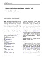
The experimental setup of the near-field optical lithogra-
phy system consists of two subsystems as shown in Fig. 1:
the lithography system and the ISPI system. In the lithogra-
phy system, bowtie aperture antennas are chosen as the
focusing element due to their ability of field localization and
enhancement at the nanometer scale.
3–5,16
A bowtie aperture
antenna is illustrated in Fig. 2(a). When the incident light is
polarized across the gap (along the y-direction), a current is
induced in the antenna and flows toward and concentrates at
the tips at the gap, which produces an optical spot as small
as the gap [Fig. 2(b)]. This near-field optical spot, on the
other hand, is subjected to strong divergence. For example, a
a)
Present address: Production Engineering Department, King Mongkut’s
University of Technology North Bangkok, Bangkok 10800, Thailand.
b)
Electronic mail:
041601-1 J. Vac. Sci. Technol. B 31(4), Jul/Aug 2013 2166-2746/2013/31(4)/041601/5/$30.00
V
C
2013 American Vacuum Society 041601-1
Downloaded 17 Jun 2013 to 128.211.166.153. Redistribution subject to AVS license or copyright; see />spot of 50 nm can double its size at a distance 50 nm from
the antenna and its intensity also drops rapidly. Therefore,
the effective working distance of a bowtie aperture antenna
during a lithography process is well below 50 nm.
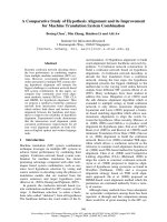
The ISPI gap detection is based on the analysis of fringes
produced by light diffraction off chirped gratings referred to
as transverse chirp gapping.
10
As shown in Fig. 3(a), the
ISPI grating pattern consists of a pair of two dimen sional
checkerboards, whose y-periodicity is uniform and the
x-periodicity is chirped oppo sitely. The y-periodicity is
designed for oblique angle to avoid interfering with the li-
thography processing beam. The x-periodicity creates inter-
ference fringes that are sensitive to the mask–substrate gap.
Since the x-periodicity is chirped, the transmitted-diffracted
angle of the incident beam will vary along the x-direction as
shown in Fig. 3(b). After reflecting from the substrate, the
transmitted-diffracted beam will reach the mask some dis-
tance away from the incident position and rediffract. All the
re-diffracted beams will then interfere and display a set of
interference fringes at the imaging plane of the ISPI micro-
scope as shown in Fig. 3(a). The position and number of the
fringes are sensitive to the gap distance. When the gap is
changed, the two sets of fringes will translate oppositely
along the x-axis due to the counter chirped direction of the
two checkerboard gratings. By analyzing the interference
signal, we can extract the frequency (i.e., the number of the
fringes shown in the x-direction) and the relative phase shift
of the two opposite fringes, and then derive the gap value
from such information.
Figure 2(c) illustrates the optical mask, which was fabri-
cated on a piece of 0.5 in. square optically flat quartz cov-
ered by a 70-nm layer of chromium. It contains several sets
(six shown) of ISPI patterns and a number of islands (four
shown). The bowtie apertures were milled on top of the
island using focused ion beam milling [Fig. 2(d)]. The use of
the islands can reduce the contact area between the mask
and the photoresist (S1805, from Shipley) sur faces, so as to
reduce the probability of contamination from dust particles.
An SEM image of the bowtie apertures is shown in Fig. 2(d).
To implement the ISPI system, its microscope is mounted
at an oblique angle above the lithography system using a 6-
axis manually controlled stage so that it can be alternated to
FIG. 1. (a) Illustration of the experimental setup; (b) photo of the experimen-
tal setup.
FIG. 2. (a) Sketch of the bowtie aperture, (b) its optical transmission inten-
sity at the exit plane, (c) sketch of the mask, and (d) SEM image of a bowtie
array on top of one island (the inset is a zoom-in image of one of the bowtie
apertures).
041601-2 Wen et al.: High precision dynamic alignment and gap control 041601-2
J. Vac. Sci. Technol. B, Vol. 31, No. 4, Jul/Aug 2013
Downloaded 17 Jun 2013 to 128.211.166.153. Redistribution subject to AVS license or copyright; see />different ISPI grating patterns on the mask during the align-
ment process. A fiber laser with a 660 nm wavelength is
attached to the microscope. It incidents onto the ISPI
patterns, diffracts through the gap between the mask and
substrate, and then reflects back to the microscope. The
angle between the incident beam and the reflect beam is set
to $4
.
The lithography process utilizes a frequency-tripled
diode-pumped solid state UV laser (k ¼ 355 nm) as the expo-
sure source. To ensure the uniformity of the exposure dose
on the entire bowtie aperture array for parallel lithography,
the laser beam is expanded to cover an area of about 2 cm
2
.
The substrate is held by a piezoelectric stage, which can
move in x-, y-, and z-directions with a 0.4 nm resolution.
Above the substrate, the mask is held by another piezoelec-
tric stage which can adjust the tip/tilt angles (h
x
, h
y
) for
alignment. The entire setup is built inside a cleanroom-grade
semiclosed box to minimize contamination from dust
particles.
III. RESULTS AND DISCUSSION
A. Gap detection and control using ISPI
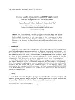
In our work, the ISPI pattern along the x-direction was
designed to be chirped as a quartic function so that the fre-
quency of the fringes would change linearly with the gap as
shown in the simulation result [Fig. 4(a), square dots]. When
an ISPI fringe image is obtained and its frequency and phase
information is analyzed, the gap value can then be obtained
using a calibrated linear equation. Figure 4(b) shows the
change of the experimental data with the height of the piezo-
electric stage. Since the position of the mask is fixed, when
the height of the piezoelectric stage is increased, the gap
between the mask and the substrate is decreased. From the
experimental data, the frequency signal shows oscillations
superimposed on the predicted linear trend. These oscilla-
tions are due to Fabry–Perot interfer ence within the gap. On
the other hand, the phase signal does not have any oscilla-
tion. Therefore, using the phase signal to determine the gap
is more reliable than frequency gapping. From calibration,
one phase cycle (2p) corresponds to about 150 nm of gap
change. The detection algorithm in our system is capable to
detect <1/1000 of a phase cycle; thus, the sensitivity of
phase gapping is 0.15 nm (150 nm/1000).
We also implemented a real-time feedback control system
to maintain the gap distance. Figures 5(a) and 5(b) illustrate
gapping with and without the feedback control. When there
is no feedback, the gap drifts for hund reds of nanometers
even when the piezoelectric stage is not moving, which can
be caused by the background noises from the vibration of the
piezoelectric stage or thermal expansion. With the feedback
control, the gap can remain at the desired value within about
4 nm. When the piezoelectri c stage moves, Fig. 5(c) shows
variation of the gap distance is about 40 nm over a scanning
distance of 100 lm without the feedback control, which can
be caused by a small tip–tilt angle from misalignment. When
FIG. 3. (a) Sketch of ISPI checkerboard gratings and typical fringe image
captured by the ISPI camera. (b) Illustration of the working mechanism of
ISPI.
FIG. 4. (a) Simulated and (b) experimental relation of the frequency and
phase of the fringes vs the gap.
041601-3 Wen et al.: High precision dynamic alignment and gap control 041601-3
JVST B - Microelectronics and Nanometer Structures
Downloaded 17 Jun 2013 to 128.211.166.153. Redistribution subject to AVS license or copyright; see />the feedback control is activated, the variation of the gap dis-
tance is limited to 6 nm [Fig. 5(d)].
B. ISPI alignment
As mentioned before, for near-field optical nanolithogra-
phy, the alignment between the mask and the substrate is
critical. For parallel lithography using multiple antennas, it
is even more important to achieve a high degree of parallel-
ism. We obtain gap values on different ISPI patters on the
mask [Fig. 2(c)] and then adjust the tip/tilt of the mask to
make sure same gap values are obtained on different ISPI
patterns and the mask is parallel to the substrate (Fig. 6).
Typically, the process of reading the gap values and adjust-
ing the tilt angles of the mask relative to the substrate needs
to be repeated several times to achieve a parallelism within
0.03 mrad. To demonstrate parallel lithography, we use a
5Â5 antenna array, which covers an area of 0.04 mm
2
.
Within this area, a tilt of 0.03 mrad corresponds to a height
difference of 6 nm.
C. Parallel nanolithography
After aligning the mask parallel to the substrate (within
0.03 mrad), the photoresist substrate is brought into contact
with the surface of the mask. The ISPI data are recorded
when the substrate is moved toward the mask as shown in
Fig. 7(a). It is seen that the gap decreases linearly when the
substrate is moving toward the mask. Then there is a sudden
turn of the slope of the gap reading, after which the gap
FIG. 5. ISPI gapping with and without feedback: (a) and (b) statically, and
(c) and (d) during scanning.
FIG. 6. Illustration of alignment using the ISPI detection: (a) before align-
ment; (b) after alignment.
041601-4 Wen et al.: High precision dynamic alignment and gap control 041601-4
J. Vac. Sci. Technol. B, Vol. 31, No. 4, Jul/Aug 2013
Downloaded 17 Jun 2013 to 128.211.166.153. Redistribution subject to AVS license or copyright; see />keeps a constant value. This indicates that the substrate has
made a contact with the mask at the point when the slope
changes. Therefore, from this contact point, the distance
between the bowtie aperture antennas and the photoresist
surface can be determined by retracting the substrate away
from the mask. This provides a means to operate with a
small gap to both minimize friction and maintain a gap dis-
tance within tens of nm for near-field nanolithography.
Figure 7(b) shows the lithography result with a gap dis-
tance of 10 nm and a scanning speed of 1.5 lm/s, under a
laser intensity of 70 mW/cm
2
. The line-width is measured to
be around 60 nm [Fig. 7(c)]. With the use of ISPI gapping
and feedback control, we are able to achieve parallel nanoli-
thography. Figure 8 shows the result of lithography using a
5Â5 bowtie aperture antenna array. The line-width of the
features is about 86 nm. The small variations among differ-
ent patterns are due to the difference among the bowtie aper-
ture antennas caused by the fabrication process.
IV. CONCLUSIONS
We demonstrated the ISPI gapping technique in parallel
nanolithography, using bowtie aperture antennas as near
field optical elements. With the use of ISPI phase gapping,
the sensitivity of gap detection can reach 0.15 nm.
Combining ISPI and dynamic feedback control, we can pre-
cisely align the mask with the substrate with a parallelism
better than 0.03 mrad, and then control the gap between the
mask and the substrate during nanolithography with a varia-
tion less than 6 nm, which offers a means to realize parallel
nanolithography.
ACKNOWLEDGMENTS
Support to this work by the Defense Advanced Research
Projects Agency (Grant No . N66001-08-1-2037) and the
National Science Foundation (Grant No. CMMI-1120577)
are gratefully acknowledged. X.W. also acknowledge the
support from the National Basic Research Program (973
Program) of China under Grant No. 2013CBA01703.
1
S. M. V. Uppuluri, E. C. Kinzel, Y. Li, and X. Xu, Opt. Express 18, 7369
(2010).
2
P. Srisungsitthisunti, O. K. Ersoy, and X. Xu, Appl. Phys. Lett. 98,
223106 (2011).
3
E. X. Jin and X. Xu, Jpn. J. Appl. Phys. 43, 407 (2004).
4
E. X. Jin and X. Xu, Appl. Phys. Lett. 86, 111106 (2005).
5
N. Murphy-DuBay, L. Wang, and X. Xu, Appl. Phys. A 93, 881 (2008).
6
H. Hwang, J G. Kim, K. W. Song, K S. Park, N C. Park, H. Yang, Y C.
Rhim, and Y P. Park, Jpn. J. Appl. Phys. 50, 09MC04 (2011).
7
W. Srituravanich, L. Pan, Y. Wang, C. Sun, D. B. Bogy, and X. Zhang,
Nat. Nanotechnology 3, 733 (2008).
8
T. Kim et al., Appl. Phys. Lett. 101, 161109 (2012).
9
E. E. Moon, P. N. Everett, M. W. Meinhold, M. K. Mondol, and H. I.
Smith, J. Vac. Sci. Technol. B 17, 2698 (1999).
10
E. E. Moon and H. I. Smith, J. Vac. Sci. Technol. B 24, 3083 (2006).
11
E. E. Moon, P. N. Everett, M. W. Meinhold, and H. I. Smith, Proceedings
of Microprocesses and Nanotechnology Conference (IEEE, New York,
2000), p. 252.
12
P. Srisungsitthisunti, E. E. Moon, C. Tansarawiput, H. Zhang, M. Qi, and
X. Xu, Proc. SPIE 7767, 776707 (2010).
13
P. Srisungsitthisunti, Ph.D. dissertation (Purdue University, 2011).
14
R. Menon, E. E. Moon, M. K. Mondol, F. J. Castano, and H. I. Smith,
J. Vac. Sci. Technol. B 22, 3382 (2004).
15
J. I. Mitchell, S. J. Park, C. A . Watson, P. Sri sungsitthisunti, C. Tansarawipu t,
M. S. Qi, A. Eric, C. Yang , and X. Xu , Opt. Eng. 50, 104301 (2011).
16
L. Wang, S. M. Uppuluri, E. X. Jin, and X. Xu, Nano Lett. 6, 361 (2006).
FIG. 7. (a) Height of the piezoelectric stage vs the gap value detected by the
ISPI. (b) and (c) AFM results of the line produced with a speed of 1.5 lm/s
and a gap of 10 nm.
FIG. 8. Result of parallel lithography with a line width of 86 nm.
041601-5 Wen et al.: High precision dynamic alignment and gap control 041601-5
JVST B - Microelectronics and Nanometer Structures
Downloaded 17 Jun 2013 to 128.211.166.153. Redistribution subject to AVS license or copyright; see />