ultra fast laser absorption and ablation
Bạn đang xem bản rút gọn của tài liệu. Xem và tải ngay bản đầy đủ của tài liệu tại đây (531.28 KB, 6 trang )
DOI: 10.1007/s00339-005-3326-x
Appl. Phys. A 81, 1627–1632 (2005)
Materials Science & Processing
Applied Physics A
i.h. chowdhury
1
a.q. wu
1
x. xu
1,✉
a.m. weiner
2
Ultra-fast laser absorption and ablation
dynamics in wide-band-gap dielectrics
1
School of Mechanical Engineering, Purdue University, West Lafayette, IN 47907, USA
2
School of Electrical and Computer Engineering, Purdue University, West Lafayette,
IN 47907, USA
Received: 30 March 2005/Accepted: 27 June 2005
Published online: 2 August 2005 • © Springer-Verlag 2005
ABSTRACT The highly nonlinear laser–matter interaction con-
ditions produced by high-intensity amplified ultra-fast laser
pulses have proven to be beneficial in the processing of nor-
mally transparent wide-band-gap dielectric materials. This art-
icle presents experimental studies of the ultra-fast laser absorp-
tion process in three wide-band-gap dielectrics: fused silica,
calcium fluoride, and sapphire. Time-resolved measurements of
the probe transmissivity and reflectivity show both the forma-
tion of dense free-electron plasma at the surface due to nonlinear
absorption of the laser pulses and rapid structural damage on
the order of a few picoseconds. Pump–probe data with intense
pump and probe pulses was also correlated to atomic force mi-
croscopy measurements of the ablated volume. It was observed
that the material removal peaked near zero delay between the
pulses and decreased within a temporal separation of about 1 ps.
PACS 52.38.Mf; 78.47.+p; 79.20.Ds
1 Introduction
Ultra-fast lasers are a unique tool for machining
a diverse range of materials. In particular, the highly nonlin-
ear laser–matter interaction conditions produced by ultra-fast
pulses are conducive to the processing of hard-to-machine
materials such as ceramics and wide-band-gap dielectrics.
Wide-band-gap dielectrics such as fused silica are normally
transparent to visible and near-infrared light as the photon en-
ergy is insufficient to excite an electron from the valence to
the conduction band by linear absorption. However, the ex-
tremely high intensities created by amplified ultra-fast laser
pulses cause nonlinear photoionization effects which lead to
significant absorption of the photons. This topic has received
considerable attention in recent years and several reviews of
the existing literature are available [1, 2]. Briefly, an electron
in the valence band can absorb several visible or near-infrared
photons and gain enough energy to cross the band gap. This
process is referred to as multiphoton ionization. Another non-
linear photoionization process that becomes important at high
electric field magnitudes is tunneling photoionization, where
the strongelectricfield suppresses theCoulombbarrier and al-
lows the electron to tunnel through. The free electrons created
✉ Fax: +1-765-494-0539, E-mail:
by nonlinear photoionization can then absorb more energy
from the laser pulse by inverse bremsstrahlung. If the energy
of the free carriers becomes high enough, they can also pro-
mote an electron from the valence to the conduction band by
impact ionization leading to an avalanche process.
The free-electron plasma created in wide-band-gap di-
electrics by the nonlinear absorption of ultra-fast laser pulses
has been observed in both time-resolved reflectivity [3] and
shadowgraph imaging experiments [4]. Vu et al. [3] ob-
served an increase in the reflectivity of fused quartz irradi-
ated with
100-fs pulses that lasted for about 10 ps. Simultan-
eous measurements of the Doppler shift of a probe reflected
from the back side of the sample revealed that the ioniza-
tion front moved into the sample with a maximum velocity of
1.8 ×10
5
m/s. Similar high-reflectivity signals of the order of
60% were observed in several different dielectric samples by
von der Linde and Schüler [5], who also noted that the thresh-
old intensity for plasma formation was close to
10
13
W/cm
2
.
Spectral interferometry studies have revealed that the free car-
riers created by the femtosecond pump pulse can be captured
very rapidly in some materials like fused silica due to the for-
mation of self-trapped excitons (STEs) [6]. A trapping time
of
150 fs was measured for fused silica while the carriers
remained free in sapphire for
100 ps. Transient absorption ex-
periments in calcium fluoride revealed a similar effect with
a STE formation time of
690 fs [7].
Time-resolved measurements of plasma emission under
double-pulse irradiation in fused silica and its correlation to
the optical breakdown threshold (OBT) have also been re-
ported [8]. It was observed that the OBT for the second pulse
gradually increased until a delay of
200 fs between the pulses
and then stayed almost constant and finally recovered slowly
to the value for single-pulse OBT in a period of about
2.5ns.
A simple rate-equation model with an exponential decay term
for the free-electron distribution could not explain the experi-
mental results. However, it was pointed out later [9] that the
results could be explained in terms of the STE effect men-
tioned above. Moreover, the STEs can act as suitable sites
for the absorption of the subsequent pulse as the electron in
the e – h pair is more weakly bound than the valence-band
electrons. The STE itself recombines over a time scale of
nanoseconds, whichcanexplain the observed recovery behav-
ior of the OBT for the second laser pulse. Thus, a combination
of absorption in the free carriers in the first few hundred fem-
toseconds and in the STE in the subsequent period was held
1628 Applied Physics A – Materials Science & Processing
responsible for the observed OBT dynamics in fused silica.
Machining of fused silica and other dielectric samples with
double- and triple-pulse sequences synthesized using a pulse
shaper has also been reported [10]. A significant difference in
the OBT under multiple-pulse irradiation of fused silica and
sapphire was observed. The OBT changed rapidly within
1ps
for fused silica, in accord with the results from the previous
studies, while the OBT for sapphire did not change much over
this time period. This is attributed to the fact that fused sil-
ica has a fast trapping of free electrons due to the STE effect
while in sapphiretheexcited carriers can remainfreefor much
longer periods. It was also observed that increasing the sep-
aration from
0.3psto 1psfor a triple-pulse sequence led to
a decrease in the amount of material ablated for the case of
fused silica but not for sapphire.
Some experiments have been carried out using pulse trains
of high repetition rate and interesting machining effects have
been reported. Herman et al. [11] used a train of
430 pulses of
1.2-ps duration each for machining fused-silica samples and
found that thesurface microcracking or swelling that occurred
with single-pulse machining could be eliminated. It was as-
sumed that the heating effects associated with the high repe-
tition rate may have improved the ductility of the surrounding
glass. Afour-pulsesequence wasalso used to machine various
materials including glass and significant changes in the ma-
chining characteristics could be observed [12]. Some amount
of enhancement in machining quality due to the use of ultra-
fast pulse trains generated by pulse shapers has also been
reported [10]. As such, it is seen that machining with a pulse
train with a repetition rate of the order of GHz to THz in-
stead of a single pulse repeated at the amplifier rate of a few
kHz could possibly offer certain advantages, combining the
positive aspects of both short- and long-pulse interactions.
However, the fundamental reasons why pulse trains could of-
fer advantages to material-removal applications are still not
very well understood.
As discussed previously, the interaction of ultra-fast laser
pulses with wide-band-gap dielectrics involves the absorption
of photons by the valence electrons and subsequent coup-
ling of the energy to the lattice. The absorption itself is quite
a complex phenomenon as the free-electron plasma generated
by the initial part of the pulse can either absorb the later part
more efficiently or act as a plasma mirror and reflect most of
the energy [13, 14]. For material-processing applications, it is
desirable that most of the energy of the pulse be absorbed in
the sample. Another question that relates to the lifetime of the
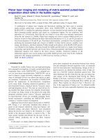
FIGURE 1 Schematic layout of pump–probe setup.
HWP: half-wave plate, PD: Si photodetector, CCD:
CCD camera, FO: focusing objective, CO: collecting
objective, P: polarizer, F: 800-nm band-pass filter
photoexcited carriers is: how long do the carriers remain free
before they are captured as STEs or in defect states? Also, the
creation of STEs can affect the absorption of the subsequent
pulses as they represent energy levels within the band gap that
can be excited much more easily. All these issues would affect
howwell thelater pulses in a train are absorbed in the material.
This article aims to resolve some of these questions by con-
ducting pump–probe experiments on different dielectric sam-
ples to identify the absorption characteristics and also relate
these to the ablation process. Sect. 2 describes the experimen-
tal setup while the results of single-pulse and time-resolved
pump–probe experiments are presented in Sect. 3.
2 Experimental setup
The experimental setup is a typical pump–probe ar-
rangement with orthogonal polarization of the two pulses as
shownin Fig. 1. The input is a
90-fs FWHM (full width at half
maximum) pulse centered at
800 nm emitted by a Ti:sapphire
regenerative amplifier. Single pulses are selected from the
1-kHz pulse train with an electromechanical shutter. A half-
wave plate (HWP) placed in the probe-beam path rotates the
probe polarization from horizontal to vertical. The power of
the pump and probe beams is controlled by using neutral-
density (ND) filters and half-wave-plate
/polarizer combina-
tions (not shown in the diagram). The pump and probe beams
are focused on the sample with a long-working-distance Mitu-
toyo objective (
10×, 0.28 NA). The sample itself is mounted
on a motorized stage so that it can be moved perpendicular to
the beam between pulses, allowing a fresh surface to be ex-
posed to each laser pulse. The transmitted part of the beam
is collected with another objective (
50×, 0.5NA) and sent to
the second photodetector (PD2). The collecting objective has
a much higher NA than the focusing objective in order to en-
sure that all the transmitted light is collected. The part of the
beam that is reflected normally is collected by the focusing ob-
jective and sent back towards the third photodetector (PD3).
Appropriate polarizers (P) and
800-nm band-pass filters (F)
were placed in front of the photodiodes to block the pump
beam and plasma light. The CCD camera along with a white-
light source (not shown in the diagram) images the surface of
the sample using the focusing objective. This helps in con-
trolling the location of the sample surface with respect to the
focal position to ensure repeatability during the experiments.
Moreover, the imaging setup can also be used to image the
air breakdown at very high incident energies. This helps to
CHOWDHURYet al. Ultra-fast laser absorption and ablation dynamics in wide-band-gap dielectrics 1629
locate the focal position at the imaging plane and hence also
the position of the sample surface with respect to the focus.
The position of the focus is not expected to vary with the in-
cident energy, since the critical power for self-focusing in air
is quite high (
1.7GW) [15] compared to typical peak powers
of about
10 MW in our experiments. The pump–probe setup
can be easily used for single-pulse measurements by blocking
the pump beam and using the vertically polarized probe beam
only. The processed samples are analyzed with an atomic
force microscope (AFM) to measure the ablated volume.
3 Results and discussion
3.1 Single-pulse measurements
Following the discussion in Sect. 1, it is expected
that, as the intensity of the incident pulse is increased, the
transmissivity should drop and the reflectivity should rise
since the free-electron plasma in the conduction band created
by nonlinear absorption of the initial part of the pulse ab-
sorbs and reflects the later part of the pulse. As the intensity
increases, more electrons are photoexcited to the conduction
band and the free electron plasma density increases. Mathe-
matically, the idea can be expressed in terms of the plasma-
frequency concept based on the Drude model [16], which
states that the reflectivity increases sharply when the plasma
frequency becomes equal to the laser frequency.
The experimentally obtained values of single-pulse trans-
missivity and reflectivity as a function of incident laser flu-
ence are shown in Fig. 2. Three different dielectric samples
were considered: calcium fluoride (
CaF
2
, 2-mm thick, Alfa
Aesar), fused silica (
SiO
2
, 1-mm thick, Corning 7980), and
sapphire (
Al
2
O
3
, 2-mm thick, Edmund Optics). The intensity
FIGURE 2 (a) Transmissivity and (b) reflectivity of a single 90-fs, 800-nm
pulse as a function of incident intensity in various wide-band-gap dielectric
samples
values quoted here are based on a beam spot size of 4 µm
(measured by a knife-edge technique) and a pulse width of
90 fs FWHM (measured by a single-shot autocorrelator and
by two-photon absorption autocorrelation in a GaP photo-
diode). The data is calibrated to obtain absolute values for
transmissivity and reflectivity by using the fact that at the low-
est intensities the free-electron density will be negligible and
hence the reflectivity and transmissivity values can be calcu-
lated from the normal refractive-index values at
λ =800nm.
As predicted by theory, the transmissivity drops and the re-
flectivity rises for all the three wide-band-gap dielectric sam-
ples as the incident intensity is increased. It is seen that the
transmissivity drop is the smallest for
CaF
2
and very simi-
lar for
SiO
2
and Al
2
O
3
. This phenomenon is partly related to
the values of the band gaps of the three materials:
12 eV for
CaF
2
[7] and 9eVfor SiO
2
[17] and Al
2
O
3
[18]. As the ab-
sorption is by nonlinear photoionization, the value of the band
gap will determine how easily the incident photons will be ab-
sorbed. A larger band gap could lead to less absorption and
hence higher transmissivity. However, at the high intensities
considered here, the effects of free-electron absorption are ex-
pected to dominate the transmissivity, as the intensity is high
enough tocreate the initial seed plasma regardless ofthe band-
gap value.
In Fig. 2, the solid line for
SiO
2
is obtained from a numer-
ical model that simulates the propagation of ultra-fast laser
pulses inside fused silica using the 2 (spatial) + 1 (temporal)-
dimensional propagation equation given below:
∂
∂z
ψ =
i
2k
∇
2
t
ψ −
W
PI
U
nc
0
ε
0
|ψ|
2
ψ −i
k
2
∂
2
ψ
∂t
2
+ik
0
n
2
nc
0
ε
0
2
|ψ|
2
ψ −
σ
2
ψ −i
σ
2
ωτψ. (1)
Here,
ψ(r, z, t) is the envelope function of the electric field,
∇
2
t
the Laplacian operator in the transverse plane, W
PI
the
photoionization rate obtained from the Keldysh theory [19],
k
the group velocity dispersion coefficient, t
=t −z/v
g
the
retarded time,
k
0
the laser wavenumber in vacuum, ε the com-
plex relative dielectric constant of excited fused silica, and
n = Re
√
ε the corresponding refractive index. The first term
on the right-hand side in (1) stands for laser diffraction in
the transverse plane, the second term accounts for absorption
due to nonlinear photoionization, and the third term repre-
sents the group-velocity dispersion. The last three terms on
the right-hand side account for self-focusing related to the
Kerreffect, free-electron absorption, and laser defocusing due
to the free electrons, respectively. A more detailed descrip-
tion of the model can be found in [20]. The evolution of the
free-electron density
ρ in fused silica is described with the
following rate equation:
dρ
dt
=(W
PI
+βIρ)
1 −
ρ
ρ
max
−
ρ
τ
s
. (2)
Here,
β is the avalanche ionization coefficient and τ
s
the elec-
tron trapping time. Together, (1) and (2) are solved numer-
ically to predictthe propagation of femtosecond pulses in bulk
fused silica, taking into account both reflection at the air–solid
interface and the absorption mechanisms in the bulk that con-
tribute to the final transmissivity value.
1630 Applied Physics A – Materials Science & Processing
FIGURE 3 Ablated volume measured with AFM as a function of incident
intensity for various wide-band-gap dielectrics
It is seen fromFig. 2 thatthe transmissivityfit isquite good
but the reflectivity prediction is much higher than the experi-
mentally observed values except at the lowest intensities. The
reason for this is that as the intensity increases, there is a con-
siderable amount of scattering of the pulse in all directions.
This was observed by using an infrared viewer fitted with an
800-nm band-pass filter. As the model does not provide for
scattering, and the experiment picks up only the normally re-
flected part of the light, the reflectivity data does not match the
model predictions. Similar experiments have been reported
by other groups [13, 14]. In these cases, the experimentally
observed reflectivity values were higher than the ones shown
here and matched model predictions quite well. The main rea-
son for this difference is due to the focusing conditions. The
experiments in the two references mentioned above used very
slow focusing lenses (
f ∼ 1000 mm), while this study uses
a very tight focusing objective. As a result, the free-electron
plasma created in this experiment is confined to a very small
volume (
∼4-µm diameter). This is expected to create a much
more uneven and unstable plasma that causes scattering in all
directions instead of specular reflection.
The volume of ablated material for a single pulse at dif-
ferent incident intensities was measured using an atomic force
microscope (AFM) and the data is presented in Fig. 3. Each
data point is averaged over five measurements and the error
bars represent the standard deviation. The larger band gap
and corresponding higher transmissivity of
CaF
2
, as seen in
Fig. 2a, would imply lower absorption in this dielectric and
hence less ablation. However, it is noticed that
Al
2
O
3
has the
smallest ablated volume. This phenomenon can be explained
in terms of the enthalpy of fusion of the three materials, which
is a measure of the bond strengths.
Al
2
O
3
has the highest en-
thalpy at
111.1kJ/mol followed by CaF
2
(29.71 kJ/mol)and
SiO
2
(8.51 kJ/mol) [21]. Because of this, it is to be expected
that even if there is less absorption in
CaF
2
, there will be
greater material removal because it can be damaged more eas-
ily. The two other materials also show the expected trend in
ablated volume corresponding to their respective enthalpies,
although there is some overlap between
CaF
2
and Al
2
O
3
at the
lower intensities that is within the margin of error.
3.2 Time-resolved measurements
As discussed in the introduction, the primary goal
of this work is to assess the effect of material removal with
a pulse train instead of a single pulse. To this end, pump–probe
experiments were carried out to measure the effect of the
free-electron plasma created by the pump pulse on the probe
transmissivity and reflectivity. A weak, vertically polarized
probe pulse at an intensity level of
0.88 ×10
13
W/cm
2
was
used. The pump pulse was horizontally polarized and four dif-
ferent intensities were considered:
1.77 ×10
13
, 4.42×10
13
,
7.96 ×10
13
,and10.61×10
13
W/cm
2
. The first value is much
below the damage threshold. The second is very near the dam-
age threshold as seen from Fig. 3 and the last two are above
the damage threshold. The pump–probe data for the three
dielectrics is shown in Fig. 4, 5, and 6 (negative delay corres-
ponds to the probe pulse arriving before the pump). Each point
in the plots corresponds to an average over five data points.
The standard deviation is calculated to be about
10%–15% for
the transmissivity values and about
20%–30% for the reflec-
tivity values. The error bars corresponding to these values are
not shown in the figure for clarity.
It is observed from the figures that all three dielectrics
show very similar temporal behavior, in contrast to previous
studies that have reported that the free carriers in these three
dielectrics have very different lifetimes ranging from
150 fs in
SiO
2
to 100 ps in Al
2
O
3
[6, 7]. There is no appreciable change
at the lowest intensity as the free-electron density excited by
the pump is still quite low. As the pump intensity is increased,
there is a sharp drop in transmissivity around
t =0 and then
a slow increase on the order of
10–100 ps. The reflectivity
shows a sharp rise at zero delay and then starts to decay after
2–3ps, finally reaching a value much below the initial reflec-
tivity afterabout
10 ps. The increase in reflectivity is due to the
creation of free-electron plasma, as was also observed in the
single-pulse experiments. As the pump intensity is increased,
there is a corresponding increase in the free-electron density
FIGURE 4 Time-resolved (a) reflectivity and (b) transmissivity of
a0.88×10
13
-W/cm
2
probe at different values of pump intensity for fused
silica
CHOWDHURY et al. Ultra-fast laser absorption and ablation dynamics in wide-band-gap dielectrics 1631
FIGURE 5 Time-resolved (a) reflectivity and (b) transmissivity of
a0.88×10
13
-W/cm
2
probe at different values of pump intensity for calcium
fluoride
FIGURE 6 Time-resolved (a) reflectivity and (b) transmissivity of
a0.88 ×10
13
-W/cm
2
probe at different values of pump intensity for sapphire
and hence the reflectivity of the probe. The difference in the
time scales of the change in transmissivity and reflectivity is
due to the fact that reflectivity is a function of the surface con-
dition while transmissivity is more of a volume phenomenon.
The sharp decrease in reflectivity after
2–3psis due to rapid
structural damage at the surface of the sample which leads to
scattering of the probe pulse, thus attenuating the reflectivity
signal. However, the transmissivity depends on the propaga-
tion of the probe through the free-electron plasma in the bulk
of the sample that lasts longer. Hence the slower dynamics
in the transmissivity signal. We would like to emphasize here
that the presence of scattering at the air–solid interface im-
plies that a complete energy balance between the incident,
reflected, and transmitted light measurements cannot be ob-
tained in the present setup. What is measured is the specular
reflection and transmission in the forward direction only.
On comparing the reflectivity curves for
Al
2
O
3
in Fig. 6
with the previous figures, it is observed that they are slightly
different. The first difference is that a higher reflectivity (and
correspondingly lower transmissivity) is observed at negative
delays when the probe pulse sees the undisturbed material.
This is attributed to the fact that, under normal conditions,
Al
2
O
3
has a higher refractive index than the other two materi-
als, which contributes to the higher reflectivity. Also, it is seen
that there is no change in the reflectivity signal at the second
intensity level of
4.42 ×10
13
W/cm
2
although there is a slight
drop in transmissivity. This could be related to the fact that
Al
2
O
3
has a higher damage threshold (due to higher enthalpy
of fusion) that was observed and discussed in the single-pulse
experiments shown in Fig. 3 above. However, due to absorp-
tion in the bulk plasma, a drop in transmissivity can still be
observed at this intensity level. At the two highest intensity
levels, a rise in reflectivity and a drop in transmissivity are
clearly observed, signifying that a dense free-electron plasma
is formed at the surface. This behavior is similar to the case of
the other two materials.
The presence of melting and resolidification during
femtosecond laser processing of fused silica has been re-
ported [22] and also melt-induced amorphization and crystal-
lization in quartz and fused-silica samples [23]. However, the
materials under investigation here are not expected to show
a huge increase in reflectivity when they liquefy. For instance,
experiments have shown that the change in reflectivity of sap-
phire on melting is quite small, as the extinction coefficient
is of the order of
10
−4
[24, 25]. Therefore, the reflectivity in-
crease that we observe must be due to the photoexcitation
of electrons from the valence to the conduction band. This
could also have the effect of breaking the bonds between the
atoms, leading to catastrophic sample damage that leads to
the sharp decrease in the reflectivity signal seen in our experi-
ments. Also, time-resolved measurements of the scattering of
a probe pulse from fused silica show that the scattering signal
rises after a delay of about
3ps, which matches exactly with
the onset of decay in our reflectivity signal [26]. However,
the thermal effect in ablation can also play a role. The exact
mechanism of surface damage needs further investigation.
In order to study the effect of time-dependent trans-
mission and reflection on laser ablation, experiments were
also conducted using two pulses with variable temporal
separation, where both the pulses have equal intensities of
10.61 ×10
13
W/cm
2
. Figure 7 shows the ablation volume vs.
temporal separation. The values for the transmissivity and re-
flectivity of the probe pulse are also plotted alongside. The
ablated volume shows a maximum near zero delay in all three
cases. In general, if the data is compared with the single-pulse
ablation results shown in Fig. 3, it is observed that the ablated
volume is slightly larger than that for a single pulse at an in-
tensity of
10.61 ×10
13
W/cm
2
for the longest delays and then
slowly increases to a value near zero delay that is compara-
1632 Applied Physics A – Materials Science & Processing
FIGURE 7 Time-resolved measurements of transmissivity, reflectivity, and
ablated volume for the case where both pump and probe pulses have equal
intensity of 10.61×10
13
W/cm
2
in (a) fused silica, (b) calcium fluoride, and
(c) sapphire. T: transmissivity, R: reflectivity, V: ablated volume
ble to that of a single pulse with double the intensity (within
the margin of error). The decrease in ablated volume with in-
creasing temporal separation is related to the interaction of the
second pulse with the free-electron plasma created by the first
pulse. Onone hand,the freeelectrons canlead toenhanced ab-
sorption of the second pulse by inverse bremsstrahlung while,
on the other hand, the reflectivity increase predicted by the
Drude model can shield the second pulse from entering the
sample. From our experimental results, it is seen that the sec-
ond effect is dominant. Also, when the delay is longer than
a few picoseconds, the surface structural damage will lead to
scattering of the second pulse.
4Conclusion
We have conducted single-pulse and pump–probe
measurements of transmissivity and reflectivity for the funda-
mental
800-nm-wavelength pulses of an amplified ultra-fast
Ti:sapphire laser in various wide-band-gap dielectric materi-
als. The single-pulse data follow the expected trends of de-
crease in transmissivity and increase in reflectivity consistent
with the creation of a free-electron plasma by nonlinear ab-
sorption of the initial part of the pulse that absorbs and reflects
the later part. In the time-resolved pump–probe experiments,
it was observed that the three dielectric materials considered
in this study –
SiO
2
, CaF
2
,andAl
2
O
3
–showedverysimilar
temporal behavior in spite of the fact that they have been re-
ported to possess widely different free carrier trapping times.
The strong reflectivity signal, corresponding to reflection by
the dense free-electron plasma, was observed to decrease
rapidly after
2–3ps, which is attributed to rapid structural
damage at the surface. Double-pulse ablation showed a max-
imum in ablated volume at zero delay and a rapid decrease
with increasing temporal separation due to plasma screen-
ing by the free electrons created by the first pulse in the
sequence.
ACKNOWLEDGEMENTS Support for this work by the Na-
tional Science Foundation and the Indiana 21st Century Research and Devel-
opment Fund is gratefully acknowledged.
REFERENCES
1 C.B. Schaffer, A. Brodeur, E. Mazur: Meas. Sci. Technol. 12, 1784
(2001)
2 S.S.Mao,F.Qu
´
er
´
e, S. Guizard, X. Mao, R.E. Russo, G. Petite, P. Martin:
Appl. Phys. A: Mater. Sci. Process. 79, 1695 (2004)
3 B T.V. Vu, O.L. Landen, A. Szoke: Phys. Plasmas 2, 476 (1995)
4 X.Mao,S.S.Mao,R.E.Russo:Appl.Phys.Lett.82, 697 (2003)
5 D. von der Linde, H. Schüler: J. Opt. Soc. Am. B 13, 216 (1996)
6F.Qu
´
er
´
e, S. Guizard, P. Martin, G. Petite, O. Gobert, P. Meynadier,
M. Perdrix: Appl. Phys. B 68, 459 (1999)
7 R. Lindner, M. Reichling, R.T. Williams, E. Matthias: J. Phys.: Condens.
Matter 13, 2339 (2001)
8 M. Li, S. Menon, J.P. Nibarger, G.N. Gibson: Phys. Rev. Lett. 82, 2394
(1999)
9 G. Petite, S. Guizard, P. Martin, F. Qu
´
er
´
e:Phys.Rev.Lett.83, 5182
(1999)
10 R. Stoian, M. Boyle, A. Thoss, A. Rosenfeld, G. Korn, I.V. Hertel: Appl.
Phys. A: Mater. Sci. Process. 77, 265 (2003)
11 P.R. Herman, A. Oettl, K.P. Chen, R.S. Marjoribanks: Proc. SPIE 3616,
148 (1999)
12 I.H. Chowdhury, X. Xu, A.M. Weiner: Proc. SPIE 4978, 138 (2003)
13 C. Ziener, P.S. Foster, E.J. Divall, C.J. Hooker, M.H.R. Hutchinson,
A.J. Langley, D. Neely: J. Appl. Phys. 93, 768 (2003)
14 G. Doumy, F. Qu
´
er
´
e, O. Gobert, M. Perdrix, Ph. Martin, P. Audebert,
J.C. Gauthier, J P. Geindre, T. Wittmann: Phys. Rev. E 69, 26402
(2004)
15 M. Mlejnek, E.M. Wright, J.V. Moloney: Opt. Lett. 23, 382 (1998)
16 N.W. Ashcroft, N.D. Mermin: Solid State Physics (Holt, Rinehart and
Winston, New York 1976)
17 Z.A. Weinberg, G.W. Rubloff, E. Bassous: Phys. Rev. B 19, 3107 (1979)
18 D.G. Hicks, P.M. Celliers, G.W. Collins, J.H. Eggert, S.J. Moon: Phys.
Rev. Lett. 91, 35502 (2003)
19 L.V. Keldysh: Sov. Phys. JETP 20, 1307 (1965)
20 Q. Wu, I.H. Chowdhury, X. Xu: Phys. Rev. B, in press
21 D.R. Lide, H.V. Kehiaian: CRC Handbook of Thermophysical and Ther-
mochemical Data (CRC, Boca Raton, FL 1994)
22 I.H. Chowdhury, X. Xu, A.M. Weiner: Appl. Phys. Lett. 86, 151110
(2005)
23 V. Koubassov, J.F. Laprise, F. Th
´
eberge, E. Förster, R. Sauerbrey,
B. Müller, U. Glatzel, S.L. Chin: Appl. Phys. A: Mater. Sci. Process. 79,
499 (2004)
24 S. Krishnan, J.K.R. Weber, R.A. Schiffman, P.C. Nordine: J. Am. Ceram.
Soc. 74, 881 (1991)
25 J.K.R. Weber, S. Krishnan, C.D. Anderson, P.C. Nordine: J. Am. Ceram.
Soc. 78, 583 (1995)
26 A. Rosenfeld, D. Ashkenasi, H. Varel, M. Wähmer, E.E.B. Campbell:
Appl. Surf. Sci. 127, 76 (1998)