gas turbine combustion alternative fuels and emissions
Bạn đang xem bản rút gọn của tài liệu. Xem và tải ngay bản đầy đủ của tài liệu tại đây (12.02 MB, 560 trang )
GAS
Turbine
Combustion
THIRD EDITION
Alternative Fuels and Emissions
CRC Press is an imprint of the
Taylor & Francis Group, an informa business
Boca Raton London New York
GAS
Turbine
Combustion
THIRD EDITION
Arthur H. Lefebvre
and
Dilip R. Ballal
Alternative Fuels and Emissions
CRC Press
Taylor & Francis Group
6000 Broken Sound Parkway NW, Suite 300
Boca Raton, FL 33487-2742
© 2010 by Taylor and Francis Group, LLC
CRC Press is an imprint of Taylor & Francis Group, an Informa business
No claim to original U.S. Government works
Printed in the United States of America on acid-free paper
10 9 8 7 6 5 4 3 2 1
International Standard Book Number-13: 978-1-4200-8605-8 (Ebook-PDF)
This book contains information obtained from authentic and highly regarded sources. Reasonable efforts
have been made to publish reliable data and information, but the author and publisher cannot assume
responsibility for the validity of all materials or the consequences of their use. The authors and publishers
have attempted to trace the copyright holders of all material reproduced in this publication and apologize to
copyright holders if permission to publish in this form has not been obtained. If any copyright material has
not been acknowledged please write and let us know so we may rectify in any future reprint.
Except as permitted under U.S. Copyright Law, no part of this book may be reprinted, reproduced, transmit-
ted, or utilized in any form by any electronic, mechanical, or other means, now known or hereafter invented,
including photocopying, microfilming, and recording, or in any information storage or retrieval system,
without written permission from the publishers.
For permission to photocopy or use material electronically from this work, please access www.copyright.
com ( or contact the Copyright Clearance Center, Inc. (CCC), 222 Rosewood
Drive, Danvers, MA 01923, 978-750-8400. CCC is a not-for-profit organization that provides licenses and
registration for a variety of users. For organizations that have been granted a photocopy license by the CCC,
a separate system of payment has been arranged.
Trademark Notice: Product or corporate names may be trademarks or registered trademarks, and are used
only for identification and explanation without intent to infringe.
Visit the Taylor & Francis Web site at
and the CRC Press Web site at
v
Contents
Preface xvii
Authors xix
1. Basic Considerations 1
1.1 Introduction 1
1.2 Early Combustor Developments 2
1.2.1 Britain 3
1.2.2 Germany 5
1.2.2.1 Jumo 004 5
1.2.2.2 BMW 003 6
1.2.3 The United States 6
1.3 Basic Design Features 8
1.4 Combustor Requirements 9
1.5 Combustor Types 10
1.5.1 Tubular 11
1.5.2 Tuboannular 11
1.5.3 Annular 12
1.6 Diffuser 14
1.7 Primary Zone 15
1.8 Intermediate Zone 16
1.9 Dilution Zone 17
1.10 Fuel Preparation 18
1.10.1 Pressure-Swirl Atomizers 18
1.10.2 Airblast Atomizer 19
1.10.3 Gas Injection 20
1.11 Wall Cooling 20
1.11.1 Wall-Cooling Techniques 22
1.12 Combustors for Low Emissions 23
1.13 Combustors for Small Engines 26
1.14 Industrial Chambers 28
1.14.1 Aeroderivative Engines 31
References 33
Bibliography 33
2. Combustion Fundamentals 35
2.1 Introduction 35
2.1.1 Deagration 35
2.1.2 Detonation 35
2.2 Classication of Flames 36
2.3 Physics or Chemistry? 37
vi Contents
2.4 Flammability Limits 37
2.5 Global Reaction-Rate Theory 38
2.5.1 Weak Mixtures 39
2.5.2 Rich Mixtures 39
2.6 Laminar Premixed Flames 41
2.6.1 Factors Inuencing Laminar Flame Speed 41
2.6.1.1 Equivalence Ratio 41
2.6.1.2 Initial Temperature 42
2.6.1.3 Pressure 42
2.7 Laminar Diffusion Flames 42
2.8 Turbulent Premixed Flames 43
2.9 Flame Propagation in Heterogeneous Mixtures of Fuel
Drops, Fuel Vapor, and Air 45
2.10 Droplet and Spray Evaporation 49
2.10.1 Heat-Up Period 50
2.10.2 Evaporation Constant 51
2.10.3 Convective Effects 52
2.10.4 Effective Evaporation Constant 52
2.10.5 Spray Evaporation 54
2.10.6 Some Recent Developments 54
2.11 Ignition Theory 55
2.11.1 Gaseous Mixtures 55
2.11.2 Heterogeneous Mixtures 56
2.12 Spontaneous Ignition 64
2.13 Flashback 69
2.14 Stoichiometry 70
2.15 Adiabatic Flame Temperature 71
2.15.1 Factors Inuencing the Adiabatic Flame
Temperature 71
2.15.1.1 Fuel/Air Ratio 71
2.15.1.2 Initial Air Temperature 71
2.15.1.3 Pressure 72
2.15.1.4 Inlet-Air Vitiation 72
Nomenclature 73
References 74
Bibliography 77
3. Diffusers 79
3.1 Introduction 79
3.2 Diffuser Geometry 81
3.3 Flow Regimes 82
3.4 Performance Criteria 83
3.4.1 Pressure-Recovery Coefcient 84
3.4.2 Ideal Pressure-Recovery Coefcient 84
Contents vii
3.4.3 Overall Effectiveness 85
3.4.4 Loss Coefcient 85
3.4.5 Kinetic-Energy Coefcient 86
3.5 Performance 86
3.5.1 Conical Diffusers 87
3.5.2 Two-Dimensional Diffusers 88
3.5.3 Annular Diffusers 89
3.6 Effect of Inlet Flow Conditions 90
3.6.1 Reynolds Number 91
3.6.2 Mach Number 91
3.6.3 Turbulence 92
3.6.4 Swirl 93
3.7 Design Considerations 93
3.7.1 Faired Diffusers 93
3.7.2 Dump Diffusers 97
3.7.2.1 Inuence of Liner Depth Ratio 98
3.7.3 Splitter Vanes 99
3.7.4 Vortex-Controlled Diffuser 100
3.7.5 Hybrid Diffuser 101
3.7.6 Diffusers for Tubular and Tuboannular
Combustors 104
3.7.7 Testing of Diffusers 105
3.8 Numerical Simulations 106
Nomenclature 108
References 109
4. Aerodynamics 113
4.1 Introduction 113
4.2 Reference Quantities 114
4.3 Pressure-Loss Parameters 114
4.4 Relationship between Size and Pressure Loss 117
4.5 Flow in the Annulus 118
4.6 Flow through Liner Holes 120
4.6.1 Discharge Coefcient 120
4.6.2 Initial Jet Angle 123
4.7 Jet Trajectories 124
4.7.1 Experiments on Single Jets 124
4.7.2 Penetration of Multiple Jets 126
4.8 Jet Mixing 129
4.8.1 Cylindrical Ducts 129
4.8.2 Rectangular Ducts 131
4.8.2.1 Inuence of Density Ratio 132
4.8.3 Annular Ducts 133
viii Contents
4.9 Temperature Traverse Quality 133
4.10 Dilution Zone Design 135
4.10.1 Craneld Design Method 136
4.10.2 NASA Design Method 137
4.10.3 Comparison of Craneld and NASA
Design Methods 137
4.11 Correlation of Pattern Factor Data 138
4.12 Rig Testing for Pattern Factor 140
4.13 Swirler Aerodynamics 140
4.14 Axial Swirlers 142
4.14.1 Swirl Number 143
4.14.2 Size of Recirculation Zone 144
4.14.3 Flow Reversal 145
4.14.4 Inuence of Swirler Exit Geometry 146
4.15 Radial Swirlers 146
4.16 Flat Vanes Versus Curved Vanes 147
Nomenclature 147
References 149
5. Combustion Performance 153
5.1 Introduction 153
5.2 Combustion Efciency 153
5.2.1 The Combustion Process 154
5.3 Reaction-Controlled Systems 154
5.3.1 Burning Velocity Model 155
5.3.2 Stirred Reactor Model 159
5.4 Mixing-Controlled Systems 160
5.5 Evaporation-Controlled Systems 161
5.6 Reaction- and Evaporation-Controlled Systems 165
5.7 Flame Stabilization 167
5.7.1 Denition of Stability Performance 167
5.7.2 Measurement of Stability Performance 168
5.7.3 Water Injection Technique 170
5.8 Bluff-Body Flameholders 173
5.8.1 Experimental Findings on Bluff-Body Flame
Stabilization 173
5.8.1.1 Homogeneous Mixtures 173
5.8.1.2 Heterogeneous Mixtures 177
5.8.2 Summary of Experimental Findings 179
5.9 Mechanisms of Flame Stabilization 179
5.9.1 Homogeneous Mixtures 181
5.9.2 Heterogeneous Mixtures 182
5.10 Flame Stabilization in Combustion Chambers 183
Contents ix
5.10.1 Inuence of Mode of Fuel Injection 184
5.10.2 Correlation of Experimental Data 185
5.11 Ignition 188
5.12 Assessment of Ignition Performance 189
5.13 Spark Ignition 190
5.13.1 The High-Energy Ignition Unit 190
5.13.2 The Surface Discharge Igniter 191
5.13.2.1 Igniter Performance 192
5.13.2.2 Igniter Design 193
5.13.2.3 Igniter Life 194
5.14 Other Forms of Ignition 195
5.14.1 Torch Igniter 195
5.14.2 Glow Plug 196
5.14.3 Hot-Surface Ignition 196
5.14.4 Plasma Jet 197
5.14.5 Laser Ignition 197
5.14.6 Chemical Ignition 198
5.14.7 Gas Addition 199
5.14.8 Oxygen Injection 199
5.15 Factors Inuencing Ignition Performance 199
5.15.1 Ignition System 200
5.15.1.1 Spark Energy 200
5.15.1.2 Spark Duration 200
5.15.1.3 Sparking Rate 202
5.15.1.4 Igniter Location 202
5.15.2 Flow Variables 203
5.15.2.1 Air Pressure 203
5.15.2.2 Air Temperature 204
5.15.2.3 Air Velocity 205
5.15.2.4 Turbulence 206
5.15.3 Fuel Parameters 207
5.15.3.1 Fuel Type 207
5.15.3.2 Fuel/Air Ratio 207
5.15.3.3 Spray Characteristics 208
5.15.3.4 Fuel Temperature 209
5.16 The Ignition Process 209
5.16.1 Factors Inuencing Phase 1 210
5.16.2 Factors Inuencing Phase 2 210
5.16.3 Factors Inuencing Phase 3 211
5.17 Methods of Improving Ignition Performance 211
5.17.1 Correlation of Experimental Data 212
Nomenclature 214
References 216
x Contents
6. Fuel Injection 221
6.1 Basic Processes in Atomization 221
6.1.1 Introduction 221
6.1.2 Breakup of Drops 222
6.1.2.1 Drop Breakup in Turbulent Flow Fields 223
6.2 Classical Mechanism of Jet and Sheet Breakup 223
6.2.1 Breakup of Fuel Jets 224
6.2.2 Breakup of Fuel Sheets 226
6.3 Prompt Atomization 227
6.4 Classical or Prompt? 228
6.5 Drop-Size Distributions 228
6.5.1 Graphical Representation of
Drop-Size Distributions 228
6.5.2 Mathematical Distribution Functions 230
6.5.3 Rosin–Rammler 231
6.5.4 Modied Rosin–Rammler 233
6.5.5 Mean Diameters 234
6.5.6 Representative Diameters 234
6.5.7 Prediction of Drop-Size Distributions 236
6.6 Atomizer Requirements 237
6.7 Pressure Atomizers 237
6.7.1 Plain Orice 238
6.7.2 Simplex 238
6.7.3 Dual Orice 239
6.7.4 Spill Return 240
6.8 Rotary Atomizers 241
6.9 Air-Assist Atomizers 242
6.10 Airblast Atomizers 243
6.10.1 Plain-Jet Airblast 243
6.10.2 Prelming Airblast 244
6.10.3 Piloted Airblast 245
6.10.4 Airblast Simplex 246
6.11 Effervescent Atomizers 249
6.12 Vaporizers 251
6.13 Fuel Nozzle Coking 254
6.14 Gas Injection 256
6.15 Equations for Mean Drop Size 256
6.16 SMD Equations for Pressure Atomizers 258
6.16.1 Plain Orice 258
6.16.2 Pressure Swirl 258
6.17 SMD Equations for Twin-Fluid Atomizers 261
6.18 SMD Equations for Prompt Atomization 264
6.18.1 Comments on SMD Equations 265
6.19 Internal Flow Characteristics 266
Contents xi
6.20 Flow Number 266
6.21 Discharge Coefcient 268
6.21.1 Plain-Orice Atomizers 268
6.21.2 Pressure-Swirl Atomizers 270
6.21.3 Film Thickness 270
6.22 Spray Cone Angle 273
6.22.1 Plain-Orice Atomizers 273
6.22.2 Pressure-Swirl Atomizers 274
6.22.2.1 Theoretical Aspects 274
6.23 Radial Fuel Distribution 276
6.24 Circumferential Fuel Distribution 280
6.24.1 Pressure-Swirl Atomizers 280
6.24.2 Airblast Atomizers 282
Nomenclature 284
References 285
7. Combustion Noise 293
7.1 Introduction 293
7.2 Direct Combustion Noise 294
7.2.1 Theory 294
7.2.2 Core Noise Prediction Methods 296
7.3 Combustion Instabilities 297
7.3.1 Descriptions of Acoustic Oscillations 297
7.3.1.1 Growl 297
7.3.1.2 Howl 298
7.3.2 Characteristic Times 298
7.3.3 Inuence of Fuel Type 299
7.3.4 Inuence of Combustor Operating Conditions 299
7.3.5 Inuence of Ambient Conditions 300
7.3.6 Aerodynamic Instabilities 300
7.3.7 Fuel-Injector Instabilities 302
7.3.8 Compressor-Induced Oscillations 303
7.3.9 LPM Combustor Noise 304
7.3.10 Test Rig Simulations 304
7.4 Control of Combustion Instabilities 305
7.4.1 Passive Control 305
7.4.2 Active Control 306
7.4.2.1 Open-Loop Systems 307
7.4.2.2 Closed-Loop Systems 307
7.4.3 Examples of Active Control 307
7.4.4 Inuence of Control Signal Frequency 309
7.5 Modeling of Combustion Instabilities 309
References 310
Bibliography 313
xii Contents
8. Heat Transfer 315
8.1 Introduction 315
8.2 Heat-Transfer Processes 316
8.3 Internal Radiation 318
8.3.1 Radiation from Nonluminous Gases 318
8.3.2 Radiation from Luminous Gases 320
8.4 External Radiation 321
8.5 Internal Convection 322
8.6 External Convection 323
8.7 Calculation of Uncooled Liner Temperature 324
8.7.1 Method of Calculation 325
8.7.2 Signicance of Calculated Uncooled Liner
Temperatures 328
8.8 Film Cooling 329
8.8.1 Wigglestrips 329
8.8.2 Stacked Ring 330
8.8.3 Splash-Cooling Ring 331
8.8.4 Machined Ring 331
8.8.5 Rolled Ring 331
8.8.6 Ζ Ring 332
8.9 Correlation of Film-Cooling Data 333
8.9.1 Theories Based on Turbulent Boundary-Layer
Model 334
8.9.2 Theories Based on Wall-Jet Model 335
8.9.3 Calculation of Film-Cooled Wall Temperature 337
8.9.4 Film Cooling with Augmented Convection 341
8.9.5 Impingement Cooling 342
8.9.6 Transpiration Cooling 343
8.10 Practical Applications of Transpiration Cooling 343
8.10.1 Transply 344
8.10.2 Lamilloy 345
8.10.3 Effusion Cooling 346
8.11 Advanced Wall-Cooling Methods 346
8.11.1 Angled Effusion Cooling 346
8.11.2 Tiles 347
8.12 Augmented Cold-Side Convection 349
8.13 Thermal Barrier Coatings 349
8.14 Materials 351
8.14.1 Metal Alloys 352
8.14.2 Ceramics 353
8.14.3 Mechanical Integrity 354
8.15 Liner Failure Modes 354
Nomenclature 355
References 356
Contents xiii
9. Emissions 359
9.1 Introduction 359
9.2 Concerns 360
9.3 Regulations 362
9.3.1 Aircraft Engines 362
9.3.2 Stationary Gas Turbines 364
9.4 Mechanisms of Pollutant Formation 366
9.4.1 Carbon Monoxide 366
9.4.1.1 Inuence of Equivalence Ratio 368
9.4.1.2 Inuence of Pressure 369
9.4.1.3 Inuence of Ambient Air Temperature 369
9.4.1.4 Inuence of Wall-Cooling Air 369
9.4.1.5 Inuence of Fuel Atomization 370
9.4.2 Unburned Hydrocarbons 370
9.4.3 Smoke 370
9.4.3.1 Inuence of Pressure 371
9.4.3.2 Inuence of Fuel Type 371
9.4.3.3 Inuence of Fuel Atomization 372
9.4.4 Oxides of Nitrogen 374
9.4.4.1 Thermal Nitric Oxide 374
9.4.4.2 Nitrous Oxide Mechanism 378
9.4.4.3 Prompt Nitric Oxide 378
9.4.4.4 Fuel Nitric Oxide 378
9.4.5 Inuence of Pressure on Oxides of Nitrogen
Formation 379
9.4.6 Inuence of Fuel Atomization on Oxides of
Nitrogen Formation 381
9.5 Pollutants Reduction in Conventional Combustors 382
9.5.1 Carbon Monoxide and Unburned
Hydrocarbons 383
9.5.2 Smoke 384
9.5.3 Oxides of Nitrogen 387
9.5.3.1 Water Injection 387
9.5.3.2 Selective Catalytic Reduction 390
9.5.3.3 Exhaust Gas Recirculation 390
9.6 Pollutants Reduction by Control of Flame Temperature 391
9.6.1 Variable Geometry 391
9.6.2 Staged Combustion 393
9.7 Dry Low-Oxides of Nitrogen Combustors 398
9.7.1 Solar Dry Low-Emissions Concepts 398
9.7.2 Siemens Hybrid Burner 400
9.7.3 General Electric DLN Combustor 401
9.7.3.1 Primary 402
9.7.3.2 Lean-Lean 403
xiv Contents
9.7.3.3 Secondary 403
9.7.3.4 Premix 403
9.7.4 ABB EV Burner 403
9.7.5 Rolls Royce RB211 Industrial Burner 406
9.7.6 EGT DLN Combustor 407
9.7.7 General Electric LM6000 Combustor 409
9.7.8 Allison AGT100 Combustor 412
9.7.9 Developments in Japan 413
9.8 Lean Premix Prevaporize Combustion 415
9.8.1 Fuel–Air Premixing 416
9.9 Rich-Burn, Quick-Quench, Lean-Burn Combustor 418
9.10 Catalytic Combustion 421
9.10.1 Design Approaches 422
9.10.2 Design Constraints 423
9.10.3 Fuel Preparation 423
9.10.4 Catalyst Bed Construction 424
9.10.5 Postcatalyst Combustion 425
9.10.6 Design and Performance 425
9.10.7 Use of Variable Geometry 427
9.10.8 Future 428
9.11 Correlation and Modeling of Oxides of Nitrogen and
Carbon Monoxide Emissions 428
9.11.1 Oxides of Nitrogen Correlations 429
9.11.1.1 Odgers and Kretschmer 429
9.11.1.2 Lewis 431
9.11.1.3 Rokke et al. 431
9.11.1.4 Rizk and Mongia 431
9.11.2 Carbon Monoxide Correlations 432
9.12 Concluding Remarks 434
Nomenclature 435
References 435
10. Alternative Fuels 443
10.1 Introduction 443
10.2 Types of Hydrocarbons 444
10.2.1 Parafns 444
10.2.2 Olens 445
10.2.3 Naphthenes 446
10.2.4 Aromatics 446
10.3 Production of Liquid Fuels 448
10.3.1 Removal of Sulfur Compounds 448
10.3.2 Contaminants 449
10.3.2.1 Asphaltenes 449
10.3.2.2 Gum 449
10.3.2.3 Sediment 450
Contents xv
10.3.2.4 Ash 450
10.3.2.5 Water 451
10.3.2.6 Sodium 452
10.3.2.7 Vanadium 452
10.3.3 Additives 453
10.3.3.1 Gum Prevention 454
10.3.3.2 Corrosion Inhibition/Lubricity
Improvers 454
10.3.3.3 Anti-Icing 454
10.3.3.4 Antistatic–Static Dissipators 454
10.3.3.5 Metal Deactivators 455
10.3.3.6 Antismoke 455
10.4 Fuel Properties 456
10.4.1 Relative Density 456
10.4.1.1 API Gravity 457
10.4.1.2 Molecular Mass 458
10.4.2 Distillation Range 458
10.4.3 Vapor Pressure 458
10.4.4 Flash Point 459
10.4.5 Volatility Point 460
10.4.6 Viscosity 460
10.4.7 Surface Tension 462
10.4.8 Freezing Point 462
10.4.9 Specic Heat 463
10.4.10 Latent Heat 465
10.4.11 Thermal Conductivity 465
10.5 Combustion Properties of Fuels 466
10.5.1 Caloric Value 466
10.5.2 Enthalpy 468
10.5.3 Spontaneous-Ignition Temperature 469
10.5.4 Limits of Flammability 470
10.5.5 Smoke Point 471
10.5.5.1 Luminometer Number 472
10.5.5.2 Smoke Volatility Index 472
10.5.6 Pressure and Temperature Effects 472
10.5.6.1 Subatmospheric Pressure 473
10.5.6.2 Low Temperature 473
10.5.6.3 High Temperature 473
10.6 Classication of Liquid Fuels 474
10.6.1 Aircraft Gas Turbine Fuels 475
10.6.1.1 Airframe 475
10.6.1.2 Engine Fuel System 476
10.6.1.3 Combustion Chamber 476
10.6.2 Aircraft Fuel Specications 476
10.6.3 Industrial Gas Turbine Fuels 476
xvi Contents
10.7 Classication of Gaseous Fuels 478
10.7.1 Gaseous Fuel Impurities 480
10.8 Alternative Fuels 481
10.8.1 Pure Compounds 481
10.8.1.1 Hydrogen 481
10.8.1.2 Methane 483
10.8.1.3 Propane 483
10.8.1.4 Ammonia 484
10.8.1.5 Alcohols 484
10.8.2 Supplemental Fuels 485
10.8.3 Slurry Fuels 485
10.9 Synthetic Fuels 486
10.9.1 Fuels Produced by Fischer–Tropsch Synthesis of
Coal/Biomass 486
10.9.2 Biofuels 488
10.9.3 Alternative Fuel Properties 489
10.9.4 Combustion and Emissions Performance 490
10.9.4.1 Fischer–Tropsch Fuels 490
10.9.4.2 Biodiesel Fuels 498
10.9.4.3 Highly Aromatic (Broad Specication)
Alternative Fuels 504
References 508
Author Index 513
Subject Index 519
xvii
Preface
Developments in gas turbine technology continue to meet the propulsion,
power, fuel efciency, and low pollutant emissions needs of the twenty-
rst century. Ten years have passed since the publication of the second
edition, which continues to be widely used in many parts of the world.
Professor Arthur Lefebvre passed away in 2003. Last year, when the pub-
lisher approached me with a proposal for preparing the third edition, I could
not refuse. After all, Professor Lefebvre was my teacher, friend, and a co-
researcher for 35 years; I was involved in numerous discussions during the
writing of the rst and second editions; and nally, I learned a great deal
from all the material presented in the book.
The book has a clear purpose; it is directed primarily toward those who
design, manufacture, and operate gas turbines in applications ranging from
aeronautical to power generation. It serves as a graduate-level textbook,
design manual, and research reference in the eld of gas turbine combus-
tion. The text is essentially self-contained and assumes only a modest prior
knowledge of physics and chemistry. In preparation for the twenty-rst cen-
tury, the second edition was thoroughly revised and updated with numer-
ous changes.
As I examined each chapter of the second edition, I found the text as up-
to-date and refreshing as ever, proving that improvements in gas turbine
combustion have been gradual and evolutionary. So minimum revisions
were required in the areas of multifuel capabilities, ame ashback, high
off- design combustion efciency, and liner failure studies with reduced
lm cooling. In the quest to achieve higher fuel efciency and decrease
carbon dioxide emissions, compressor pressure ratios and turbine inlet
temperatures gradually increased in the last decade. Yet gaseous and par-
ticulate emissions decreased by one third or more and are well below the
emissions regulations in effect as of July 2006. Thus, Chapter 9 on emissions
was updated.
The most signicant change has been the addition of a new Chapter 10,
“Alternative Fuels” and the book’s subtitle Alternative Fuels and Emissions.
Today, the ever-rising cost of petroleum fuel is prompting research into
developing alternative liquid fuels based on coal, biomass, and other feed-
stock. Depleting global resources of petroleum fuel combined with increasing
terrorist activities are leading various industrialized and developing coun-
tries to develop domestic sources of fuel for assured supply and energy secu-
rity. These domestically produced alternative fuels have to be capable of using
the available infrastructure of fuel rening, transportation, distribution, and
consumption. The future of the alternative fuel industry in the forthcoming
decade depends upon the right fuel properties and handling characteristics
xviii Preface
for the engines and infrastructure already in place; environmental impact,
which includes competition with food, water, and land; CO
2
life cycle analysis
and carbon footprint issues; and economics of return on investment, produc-
tion, and sustainability.
Accordingly, Chapter 10 presents the physical and chemical properties of
conventional (petroleum-based) liquid and gaseous fuels for gas turbines.
Next, properties of alternative (synthetic) fuels and conventional–alternative
fuel blends are reviewed. The inuence of these different fuels and their blends
on combustor performance, design, and emissions is described. Reference is
made to the special requirements of aircraft fuels and the problems encoun-
tered with fuels for industrial gas turbines.
By not deviating from the highly successful formula of the rst and second
editions, I have been able to bring all the relevant material up to date through
2009. I hope that this third edition will nd favorable acceptance among the
gas turbine combustion, fuels, and emissions community.
Finally, I would like to thank my wife Shubhangi for her help and encour-
agement during the preparation of this book.
Dilip R. Ballal
Dayton, Ohio
xix
Authors
Arthur H. Lefebvre (1923–2003) was Emeritus professor at Purdue University.
With industrial and academic experience spanning more than four decades,
he wrote over 150 technical papers on both fundamental and practical aspects
of atomization and combustion. The honors he received include the ASME
Gas Turbine and ASME R. Tom Sawyer Awards, ASME George Westinghouse
Gold Medal, and the IGTI Scholar Award. He was also the rst recipient of
the AIAA Propellants and Combustion Award.
Dilip R. Ballal is the Hans von Ohain Distinguished Chair Professor at the
University of Dayton. He has four decades of experience in the eld of gas
turbine fuels and combustion, engine aerodynamics, heat transfer, and uid
mechanics. During this period, he worked on numerous fundamental and
practical problems related to gas turbine fuels and combustion. He is a Life-
Fellow of both ASME and AIAA, ASME Senior Vice President and editor of
the ASME Journal of Engineering for Gas Turbines and Power. He has served on
the National Academies Study Committees on “Gas Turbine Propulsion” and
“Aeroengine Fuel Efciency.” His honors include the ASME-IGTI Aeroengine
Technology Award, the AIAA Airbreathing Propulsion Award, the AIAA
Propellants and Combustion Award, and the AIAA Energy Systems Award.
1
1
Basic Considerations
1.1 Introduction
The primary purpose of this introductory chapter is to discuss the main
requirements of gas turbine combustors and to describe, in general terms,
the various types and congurations of combustors employed in aircraft and
industrial engines. The principal geometric and aerodynamic features that
are common to most types of gas turbine combustors are briey reviewed,
with special attention being given to fuel preparation and liner-wall cooling
to reect the important role these topics continue to play in combustor devel-
opment. Reference is made to most of the key issues involved in combustor
design and development, but the descriptive material is necessarily brief
because these and other important aspects of combustor performance are
described more fully in subsequent chapters.
Bearing in mind the pressures and exigencies of wartime Britain and
Germany, and the lack of knowledge and experience available to the designer,
it is perhaps hardly surprising that the rst generation of gas turbine com-
bustors were characterized by wide variations in size, geometry, and the
mode of fuel injection. With the passage of time and the post-war lifting of
information exchange, some commonalities in design philosophy began to
emerge. By around 1950, most of the basic features of conventional gas tur-
bine combustors, as we know them today, were rmly established.
Since that time, combustor technology has developed gradually and con-
tinuously, rather than through dramatic change, which is why most of the
aero-engine combustors now in service tend to resemble each other in size,
shape, and general appearance. This close family resemblance stems from
the fact that the basic geometry of a combustor is dictated largely by the need
for its length and frontal area to remain within the limits set by other engine
components, by the necessity for a diffuser to minimize pressure loss, and
by the requirement of a liner (ame tube) to provide stable operation over a
wide range of air/fuel ratios. During the past half century, combustion pres-
sures have risen from 5 to 50 atmospheres, inlet air temperatures from 450 to
900 K, and outlet temperatures from 1100 to 1850 K. Despite the continually
increasing severity of operating conditions, which are greatly exacerbated
2 Gas Turbine Combustion: Alternative Fuels and Emissions, Third Edition
by the concomitant increases in compressor outlet velocity, today’s combus-
tors exhibit close to 100% combustion efciency over their normal operating
range, including idling, and demonstrate substantial reductions in pollutant
emissions. Furthermore, the life expectancy of aero-engine liners has risen
from just a few hundred hours to many tens of thousands of hours.
Although many formidable problems have been overcome, the challenge of
ingenuity in design still remains. New concepts and technology are needed to
further reduce pollutant emissions and to respond to the growing requirement
of many industrial engines for multifuel capability. Gas turbines are “omniv-
orous” machines, capable of operating efciently on a wide variety of cheap
fuels, solid, liquid, and gaseous, with the exception of aircraft engines. Today,
the ever-rising cost of petroleum fuel is prompting research into developing
alternative liquid fuels and this is posing new combustor design challenges.
Another problem of increasing importance is that of acoustic resonance, which
occurs when combustion instabilities become coupled with the acoustics of the
combustor. This problem could be crucial to the future development of lean
premixed combustors.
It is clearly important that combustor developments should keep pace with
improvements in other key engine components. Thus, reduction of combus-
tor size and weight will remain an important requirement for aero engines,
whereas the continuing trend toward higher turbine inlet temperatures will
call for a closer adherence to the design temperature prole at the turbine
inlet. Simultaneously, the demand for greater reliability, increased durability,
and lower manufacturing, development, and maintenance costs seems likely
to assume added importance in the future. To meet these challenges, the
search goes on for new materials and new methods of fabrication to simplify
basic combustor design and reduce cost. The search has already led to the
development of advanced wall-cooling techniques and the widespread use
of thermal barrier refractory coatings within the combustion liner.
1.2 Early Combustor Developments
The material contained in this book is largely a chronicle of developments
in gas turbine combustion during the last half century. For both British
and German engineers, the development of a workable combustor was an
obstacle that had to be overcome in their independent and concurrent efforts
to achieve a practical turbojet engine. It proved to be a formidable task for
both groups and, in Whittle’s case, combustion problems dominated the rst
three years of engine development. The following abridged account of the
early history of gas turbine combustion in Britain, Germany, and the United
States is intended to cover the period from the start of World War II until
around 1950, by which time it was generally accepted that the piston engine
Basic Considerations 3
had reached its limit as a propulsion system for high-speed ight and the
gas turbine was rmly established as the powerplant of choice for aircraft
applications.
1.2.1 Britain
One method of preparing a liquid fuel for combustion is to heat it above
the boiling point of its heaviest hydrocarbon ingredient, so that it is entirely
converted into vapor before combustion. This was the method adopted by
Whittle for his rst turbojet engine. This engine employed 10 separate tubular
combustors in a reverse-ow arrangement to permit a short engine shaft.
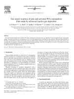
Whittle tried several vaporizer tube congurations, more than 30 in all, one
of which is illustrated in Figure 1.1. This gure shows that fuel was heated in
tubes located in the ame zone. The fuel was maintained at high pressure so
that vaporization could not occur until it had been injected through a nozzle
and its pressure reduced to that of the combustion zone. Whittle experienced
considerable difculties with this system, due mainly to problems of thermal
cracking and coking up of the vaporizer tubes, as well as difculties in con-
trolling the fuel ow rate.
After many trials and setbacks, Whittle adopted a combustor whose main
attraction was the replacement of vaporizer tubes by a pressure-swirl atom-
izer having a wide spray cone angle. Another interesting feature of the new
combustor was that most of the primary-zone airow entered the combus-
tion zone through a large air swirler located at the upstream end of the liner
around the fuel nozzle, as shown in Figure 1.2. This swirler served to create
a toroidal ow reversal that entrained and recirculated a portion of the hot
combustion products to mix with the incoming air and fuel. This arrange-
ment not only anchored the ame, but also provided the rapid mixing of
fuel vapor, air, and combustion products needed to achieve high heat-release
rates. The additional air required to complete combustion and reduce the gas
temperature to a value acceptable to the turbine was supplied through stub
Efflux gases
Pilot starting jet
Vaporizing tubes
Air entry
FIGURE 1.1
Early Whittle vaporizer combustor.
4 Gas Turbine Combustion: Alternative Fuels and Emissions, Third Edition
pipes that projected radially inward and through holes pierced in the liner
walls. After suitable development, this combustor was adopted for the Power
Jets W1 engine, which made the rst British turbojet-powered ight on the
evening of May 15, 1941.
Another early British engine was the De Havilland Goblin, which was the
rst engine to power the Lockheed P-40. (It was later replaced by General
Electric’s I-40 engine, which provided 33% more thrust.) The Goblin is of his-
torical interest because it was the rst British engine to use “straight-through”
combustors, as opposed to the “reverse-ow” type employed on all previous
engines. The rst British annular combustor appeared on the Metropolitan
Vickers Beryl engine. A noteworthy feature of this combustor was the use of
upstream fuel injection. This system was also used in other engines, the ear-
liest example being the German Jumo 004. The main advantage claimed for
upstream fuel injection was a longer residence time of the fuel droplets in the
combustion zone, which provided more time for fuel evaporation. Its main
drawback stemmed from the immersion of key components in the ame.
Cooling arrangements for the atomizer feed arm could be provided, but it
was difcult to eliminate entirely the problem of carbon deposition on the
atomizer face. For this reason, upstream fuel injection is no longer regarded
as a practical option.
Another interesting feature of the Metrovick combustor is the manner in
which dilution air was introduced into the combustion gases downstream
of the primary combustion zone. This corresponds closely to the method
employed in the Jumo 004. Figure 1.3 shows two rows of narrow scoops that
interleave cold airstreams between co-owing streams of hot combustion
products. The rst row of scoops provided air for the completion of combus-
tion, with any excess serving as dilution air. The air owing through the sec-
ond row of scoops was solely for dilution purposes. This type of “sandwich”
mixer has useful advantages in terms of low pressure loss and low pattern
factor. However, it carries a high weight penalty, which is clearly a serious
drawback for aircraft engines, and the scoops are also prone to burnout
Stub pipes
Swirl vanes
Atomizer
Efflux gases
Air inlet
FIGURE 1.2
Early Whittle atomizer combustor.