formation of zno thinfilms consisting of nano-prisms and nano-rods with a high
Bạn đang xem bản rút gọn của tài liệu. Xem và tải ngay bản đầy đủ của tài liệu tại đây (782.28 KB, 5 trang )
Formation of ZnO thin films consisting of nano-prisms and nano-rods with a high
aspect ratio by a hydrothermal technique at 60
C
Ye Bin Kwon
a
, Seung Wook Shin
b
, Hyun-Ki Lee
a
, Jeong Yong Lee
b
, Jong-Ha Moon
a
, Jin Hyeok Kim
a
,
*
a
Department of Materials Science and Engineering, Chonnam National University, 300 Yongbong e Dong, Puk-Gu, Gwangju 500-757, Republic of Korea
b
Photonics Technology Research Institute, Department of Materials Science and Engineering, KAIST, Daejeon 305-701, Republic of Korea
article info
Article history:
Received 6 September 2010
Received in revised form
22 November 2010
Accepted 26 November 2010
Available online 4 December 2010
Keywords:
ZnO thin film
Nano structure
Hydrothermal technique
Low growth temperature
abstract
ZnO thin films that consist of elongated nano-prisms and nano-rods were successfully grown on 100 nm-
thick ZnO seeded glass substrates by hydrothermal synthesis at 60
C and pH 10.3 in an aqueous solution
containing Zn(NO
3
)$6H
2
O, Al(NO
3
)
3
$9H
2
O, Na
3
-citrate and NH
4
OH. The effect of Al(NO
3
)$6H
2
O and
Na
3
-citrate, as surfactant chemicals, on the structural, morphological, optical and electrical properties of
ZnO thin films were investigated. X-ray diffraction results showed that all the deposited films were
grown as a polycrystalline wurtzite hexagonal phase with a c-axis preferred, out-of-plane orientation
and without unwanted second phase. ZnO thin films deposited without any surfactant chemicals or
deposited only with Al(NO
3
)$6H
2
O consist of elongated needle shaped nano-rods with a very rough
surface morphology. On the other hand, ZnO thin films prepared using Na
3
-citrate as a surfactant
chemical consist of hexagonal nano-prisms with a very smooth surface morphology. The thickness of the
ZnO thin films with the very smooth surface morphology was increased remarkably using both
Na
3
-citrate and Al(NO
3
)$6H
2
O as surfactant chemicals, in which ZnO thin films consisted of el ongated
hexagonal nano-prisms. These results show that relatively thick ZnO thin films with a good surface
morphology can be grown easily by the appropriate use of surface modifying chemicals, such as
Na
3
-citrate and Al(NO
3
)$6H
2
O. The photoluminescence results showed strong defect-related emission
peak centered near 545 nm in the rough surfaced ZnO thin film grown without any surfactant chemicals
and strong band-edge peak centered near 368 nm in the smooth surfaced ZnO thin film grown using
both Na
3
-citrate and Al(NO
3
)$6H
2
O as the surfactant chemicals.
Ó 2010 Elsevier B.V. All rights reserved.
1. Introduction
Zinc oxide (ZnO) is considered the most promising candidate for
a range of applications including room temperature ultraviolet
lasers transparent conducting electrodes, light emitting diodes,
sensors and surface-acoustic wave devices owing to its unique
properties such as wide band gap (E
g
¼ 3.37 eV), large exciton
binding energy (60 meV) and strong-chemical stability compared
to other materials [1e5]. In particular, the device performance of
nano-scale ZnO crystals with various morphologies, such as nano-
rod, belt, wire and tubes are superior to those of the bulk-scale due
to the quantum-sized effects [6,7]. Nano-scale ZnO thin films can be
synthesized by several methods, such as metal organic chemical
vapor deposition [8], pulsed laser deposition [9], solvothermal [10]
and hydrothermal technique [11e14]. Among these, the hydro-
thermal technique is one of the most attractive for industrial use
because industrial processes generally require rapid, low process
costs, which are the main advantages of the hydrothermal tech-
nique [15].
On the other hand, the performance of ZnO thin film devices
with a continuous, dense and smooth surface microstructure is
superior to that of ZnO thin film devices with discontinuous,
defective and rough surface microstructures [16,17]. As a result, it is
desired to grow high quality ZnO thin films by controlling the
microstructure with varying process parameters.
Na
3
-citrate is used widely to change the morphology of hydro-
thermally grown ZnO thin films grown from a needle structure to
a hexagonal prism structure due to easily adjusting the surfactant
ions for Zn
2þ
[17]. Our previous reports [18,19] also showed that the
morphology of ZnO thin films can be controlled by introducing
chemical species in the reaction solution, in which the surfactant
ions inhibit needle shape growth. Although ZnO thin films with a
smooth and dense microstructure were obtained using Na
3
-citrate
as a surfactant chemical, the growth rate of ZnO thin films in the
c-axis direction was poor, causing an increase in the growth
processing time. Therefore, it required a new approach to increase
*
Corresponding author. Tel.: þ82 62 530 1709; fax: þ82 62 530 1699.
E-mail address: (J.H. Kim).
Contents lists available at ScienceDirect
Current Applied Physics
journal homepage: www.elsevier.com/locate/cap
1567-1739/$ e see front matter Ó 2010 Elsevier B.V. All rights reserved.
doi:10.1016/j.cap.2010.11.086
Current Applied Physics 11 (2011) S197eS201
the growth rate of ZnO crystal in the c-axis direction with keeping
hexagonal prism shape rather than needle likes shape.
The purpose of this study is to grow dense and smooth ZnO thin
films with high growth rate. We report that it is possible to grow
a ZnO thin film that consists of ZnO nano-scale hexagonal prisms
with a high growth rate by using both Na
3
-citrate and Al(NO
3
)$
6H
2
O as surfactant chemicals in the hydrothermal synthesis at
60
C.
2. Experimental details
Zinc nitrate hexahydrate (Zn(NO
3
)$6H
2
O) was used to grow ZnO
crystals, and aluminum nitrate hexahydrate (Al(NO
3
)$6H
2
O) and
tri-sodium citrate (Na
3
C
6
H
5
O
7
) were used as surfactant chemicals
to control the shape of the ZnO crystals. Four different solutions,
defined as solutions A, B, C and D in Table 1, were used to grow the
ZnO thin films. Solution A was formulated with 0.03 M of Zn(NO
3
)$
6H
2
O dissolved in 80 ml of deionized (DI) water. Solution B was
formulated with 0.03 M of Zn(NO
3
)$6H
2
O and 4 mM of Na
3
C
6
H
5
O
7
dissolved in 80 ml of DI water. Solution C was formulated with
0.03 M of Zn(NO
3
)$6H
2
O and 5 mM of Al(NO
3
)$6H
2
O dissolved in
80 ml of DI water. Solution D was formulated with 0.03 M of Zn
(NO
3
)$6H
2
O, 5 mM of Al(NO
3
)$6H
2
O and 4 mM of Na
3
C
6
H
5
O
7
dis-
solved in 80 ml of DI water. 100 nm-thick ZnO seeded substrates,
which were deposited by RF magnetron sputtering at room
temperature, were cleaned sequentially in acetone and isopropyl
alcohol. The substrates were then fixed to a Teflon insert with the
ZnO seed layer side facing down within a fluoropolymer digestion
vessel (Savillex, MN, USA), which was placed into an oven at 60
C
for 6 h. The lid to the vessel was sealed to prevent evaporation. At
the end of the period, the vessel was cooled to room temperature to
remove the specimens and the specimens were rinsed in DI water.
The surface and cross-sectional morphologies of deposited thin
films were examined by field emission scanning electron micros-
copy (FE-SEM, JSM-6710F, JEOL, Tokyo, Japan). The crystallographic
information was obtained by X-ray diffraction (XRD, X’pert PRO,
Philips, and Eindhoven, Netherlands). The microstructure and
crystallographic orientation of the deposited thin films were
analyzed by transmission electron microscopy (TEM, JEM 2000EX,
JEOL, Tokyo, Japan). The optical properties of the deposited thin
films were determined by UVevis spectroscopy (Cary 100, Varian,
Mulgrave, Australia) at room temperature. The photoluminescence
(PL) properties of the deposited thin films were characterized by
room temperature (RT) PL (APD, SH-4, USA). The electrical char-
acteristics of the deposited thin films were characterized by Hall
Effect measurements (Van der Paw configuration, USA).
3. Results and discussion
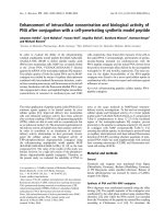
Fig. 1 shows XRD patterns of the ZnO thin films grown in solu-
tions A, B, C and D at 60
C for 6 h. All the films showed only (000l)
reflection family of ZnO without any other peaks corresponding to
other planes (JCPDS No. 89-1397 (ZnO)), indicating that all the films
had a polycrystalline hexagonal wurtzite structure with a c-axis
preferred, out-of-plane orientation. The samples grown in solutions
A and D showed a relatively strong (0002) peak intensity compared
to samples grown in solutions B and C. The full width at half
maximum (FWHM) values of the ZnO (0002) peak for the deposited
thin film grown in solution C are smaller than those grown in
solutions A and B. The smallest FWHM value of 0.32
for the ZnO
(0002) peak was observed in the sample grown in solution D,
indicating the best c-axis preferred, out-of-plane orientation.
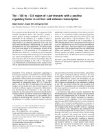
Fig. 2(a,b,c,d) shows tilted-view FE-SEM images of ZnO thin
films grown on the ZnO seeded glass substrates in solutions A, B, C
and D, respectively. The inset images show the corresponding plan-
view surface morphology of the ZnO thin films. ZnO thin films
consisting of needle shaped nano-rods were observed in the
samples grown in the solution without Na
3
C
6
H
5
O
7
as the surfactant
chemical (Fig. 2(a,c)). The surface morphology of ZnO thin films was
rough and discontinuous and the lengths of the ZnO nano-rods
were w1500 nm (Fig. 2(a)) and w500 nm (Fig. 2(c)). On the
contrary, ZnO thin films consisting of nano-prisms were observed
in the samples grown in the solutions containing Na
3
C
6
H
5
O
7
(Fig. 2
(b,d)). A smooth and dense surface morphology was observed in
those samples and the lengths of the ZnO nano-prisms were
w200 nm (Fig. 2(b)) and w1000 nm (Fig. 2(d)).
Noticeable information was obtained from the aforementioned
XRD and FE-SEM results. ZnO thin films with a dense and contin-
uous microstructure and reduced growth rate could be synthesized
in the sample grown in solution B by introducing Na
3
C
6
H
5
O
7
as the
surfactant chemical. However, a dramatic decrease in the thickness
of the ZnO film, which was typically observed in the ZnO growth
process using Na
3
C
6
H
5
O
7
as the only surfactant chemical [18],was
not observed in the sample grown in solution D, which contained
both Na
3
C
6
H
5
O
7
and Al(NO
3
)$6H
2
O as the surfactant chemicals.
These characteristics were attributed to the surfactant ions. It is
well known that the oppositely charged ions produce positively
charged Zn (0001) and negatively charged O (000l) surfaces,
resulting in a normal dipole moment and spontaneous polarization
along the c-axis as well as a variance in surface energy [15].
However, ZnO thin film grown using surfactant specifically absor-
bed on Zn-terminated (0001) planes of ZnO to slow down the
Table 1
Experimental conditions to prepare different solution of specimens.
Solution A Solution B Solution C Solution D
Zn(NO
3
)$6H
2
OO O O O
Al(NO
3
)$6H
2
OX X O O
Na
3
-citrate X O X O
Fig. 1. XRD patterns of the ZnO thin film grown on ZnO seeded glass substrate in
different solutions at pH 10.3 for 6 h.
Y.B. Kwon et al. / Current Applied Physics 11 (2011) S197eS201S198
growth rate in the [0001] direction. Especially, the morphology of
ZnO thin film using solution B showed nano-prism structure,
indicating that the Na
3
-citrate acted the fully remove for electrical
charges in surface [18]. For ZnO thin film grown in solution C, the
thickness of film was thin compared to that grown in solution A.
This behavior was attributed to the Al(NO
3
)$6H
2
O as the surfactant
chemical. The Na
3
C
6
H
5
O
7
is more dominant than Al(NO
3
)$6H
2
O
(Fig. 2(b,c)). However, the morphology of ZnO thin film grown in
solution D was high aspect ratio nano-prism with a smooth surface
as compared to these grown in solution B and C. This phenomenon
might be explained by considering the role of Al
3þ
ions during the
hydrothermal process. There were three more additive ions of Na
þ
,
C
6
H
5
O
7
3À
and Al
3þ
in solution D compared to solution A, which had
no surfactant chemicals. It is well known that C
6
H
5
O
7
3À
ions inhibit
the growth of ZnO crystals in the c-axis direction, which results in
the formation of hexagonal prism-shaped ZnO rods with a low
aspect ratio. It seems that Al
3þ
ions suppress the role of C
6
H
5
O
7
3À
ions by reducing the concentration of C
6
H
5
O
7
3À
ions through the
possible formation of an AlC
6
H
5
O
7
compound in solution. There-
fore, ZnO thin film grown in solution D consists of elongated nano-
prisms with a smooth surface.
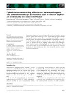
Fig. 3 shows a cross-sectional bright-field TEM image of the ZnO
thin film grown in solution D. The inset is the corresponding
selected area electron diffraction (SAED) pattern obtained at the
interface. The film consisted of dense nano-scale elongated ZnO
crystals (w20 nm in width) grown from the ZnO seeded layer. The
interfaces between the ZnO thin film, ZnO seeded layer and
substrate were very sharp without any indication of an interfacial
reaction or any formation of amorphous compounds. The SAED
pattern showed that the film was c-axis oriented in the substrate
normal direction with a slight out-of-plane variation. This TEM
result is consistent with the XRD and SEM results shown in Figs. 1
and 2.
Fig. 4 shows a plot of (
a
h
y
)
2
as a function of the photon energy of
the ZnO thin films grown on the ZnO seeded glass substrates in the
four different solutions. The band gap energy was derived by
Fig. 2. The tilted-view FE-SEM images of ZnO thin film grown on a ZnO seeded glass substrate in solutions A (a), B (b), C (c), and D (d), respectively.
Fig. 3. The cross-sectional bright-field TEM image of the ZnO thin films grown on ZnO
seeded glass substrates in solution D at pH 10.3 for 6 h.
Y.B. Kwon et al. / Current Applied Physics 11 (2011) S197eS201 S199
extrapolating the straight-line portion of the (
a
h
y
)
2
vs h
y
plot to
a zero absorption coefficient value. The optical band gap energies of
the thin films grown in different solutions A, B, C and D were
3.25 eV, 3.2 eV, 3.3 eV and 3.33 eV, respectively. The abortion edges
of the thin films grown in solutions A, C and D were approximately
365 nm except for the films grown in solution B (w355 nm). The
wider band gap energy of ZnO thin film grown in C and D than
those grown in solution A and B were attributed to the Al(NO
3
)$
6H
2
O, indicating that the Al
3þ
ions substitute for Zn
2þ
ions in the
hexagonal ZnO crystal structure. The substituted Al
3þ
ions can be
generated excess electron and finally band gap energy is wider.
Fig. 5 shows the RT PL spectra of ZnO films grown in four
different solutions on the ZnO seeded glass substrates. Two emis-
sion peaks were observed in ultraviolet (UV, w377 nm) and visible
(Vis, w560 nm) regions in all samples. The UV emission was
attributed to recombination between electrons in the conduction
band and holes in the valence band and visible emission is related
to the defects in the ZnO [20]. The UV emission of ZnO thin films
grown in the solutions containing Na
3
C
6
H
5
O
7
(solutions B and D)
shifted towards a lower wavelength compared to those grown in
the solutions without Na
3
C
6
H
5
O
7
(solutions A and C). The intensi-
ties of visible emission of the ZnO thin films with Na
3
C
6
H
5
O
7
(solutions B and D) were lower than those of without Na
3
C
6
H
5
O
7
(solution A and C) indicating low defect densities in the thin films
with Na
3
C
6
H
5
O
7
(solution B and D) [18].
Fig. 6 shows the electrical resistivity, carrier concentration and
mobility of the ZnO thin film grown in solutions A and D. The ZnO
thin film grown in solution D showed a better resistivity, carrier
concentration and mobility of 2.15 Â 10
À1
U
cm, 4.17 Â 10
18
cm
À3
and 6.98 cm
2
V
À1
S
À1
, respectively, compared to those of the ZnO
thin film grown in solution A, i.e., 8.06 Â 10
0
U
cm, 1.23 Â 10
18
cm
À3
,
and 6.35 cm
2
V
À1
S
À1
.
These improved PL and electrical properties of ZnO thin films
grown in solution D compared to those grown in solution A was
attributed to the Al(NO
3
)
3
$9H
2
O and Na
3
-citrate as surfactant
chemicals. These chemicals resulted in different morphology,
crystallinity and microstructure of the deposited thin films (Figs. 1
and 2). The Al(NO
3
)
3
$9H
2
O acted impurity of ZnO structure as well
as surfactant chemicals. From FE-SEM images of ZnO thin films
grown in solutions C and D, the Al(NO
3
)
3
$9H
2
O was kept the
continuous film with smooth morphology. The continuous ZnO thin
films grown in solution D showed better crystallinity and
a smoother morphology than those grown in solution A with
discontinuous morphology. The surface morphology and crystal-
linity of the ZnO thin films were reported to affect their PL and
electrical properties. Many defects in ZnO thin films act as free
3.0
3.1 3.2 3.3 3.4 3.5
(αhυ)
2
(arb.unit)
hυ (eV)
Solution A
Solution B
Solution C
Solution D
Fig. 4. The plot of (
a
h
y
)
2
vs photon energy of the ZnO thin film grown on ZnO seeded
glass substrate in different solutions.
300 400 500 600 700 800
362
368
377
Wavelength (nm)
Intensity (arb. unit)
Solution C
Solution D
Solution A
Solution B
Fig. 5. RT PL spectra of the ZnO thin film grown on ZnO seeded glass substrate in
different solutions.
10
-1
10
0
10
1
Solution D
Solution A
5.0x10
18
1.0x10
19
2
4
6
8
10
Resistivity
(
cm)
Carrier concentration (cm
-3
)
Mobility (
cm
2
V
-1
s
-1
)
Resistivity
Carrier concentration
Mobility
Fig. 6. The electrical resistivity, carrier concentration and mobility of the ZnO thin film
grown on ZnO seeded glass substrate in solutions A and D.
Y.B. Kwon et al. / Current Applied Physics 11 (2011) S197eS201S200
electron trap centers, which reduce the charge carrier concentra-
tion and show a high intensity of deep-level emission results from
defect-related emission in the thin film indicating the deterioration
of characteristics. In addition, the small grain size and empty space
reduces the mean free path of the free electron, leading to an
increase in film resistivity. In addition, the impurity of ZnO struc-
ture, which released the free electron, resulted in the improved
carrier concentration of ZnO thin film grown in solution D
compared that grown in solution A (Fig. 6).
4. Conclusion
It was possible to grow dense and smooth ZnO thin films with an
improved growth rate using Na
3
C
6
H
5
O
7
and Al(NO
3
)$6H
2
Oas
surfactant chemicals during hydrothermal synthesis at 60
C. The
ZnO thin films consisted of elongated hexagonal nano-prisms with
a dense microstructure and smooth surface morphology. The films
showed improved photoluminescence and electrical properties.
Acknowledgements
This work was supported partially by Energy R&D program
(2008-N-PV08-P-08) under the Korea Ministry of Knowledge
Economy (MKE) and partially by the National Research Foundation
of Korea (NRF) grant funded by the Korean government (MEST).
(No. 2010-0007691)
References
[1] C. Klingshirn, Phys. Status Solid B 71 (1975) 547.
[2] J.J. Chen, F. Zeng, D.M. Li, J.B. Niu, F. Pan, Thin Solid Films 485 (2005) 257.
[3] M. Tadatsugu, Semicond. Sci. Technol. 20 (2005) S35.
[4] T. Gao, T.H. Wang, J. Appl. Phys. A 80 (2005) 1451.
[5] G.Q. Ding, M.J. Zheng, W.L. Xu, W.Z. Shen, Nanotechnol 16 (2005) 1285.
[6] Y.G. Chul, W. Chunrui, P.W. Ii, Semicond. Sci. Technol. 20 (2005) S22.
[7] Fan Zhiyong, L.G. Jia, J. Nanosci. Nanotechnol. 5 (2005) 1561.
[8] J. Dai, H. Liu, W. Fang, L. wang, Y. Pu, Y. Cen, F. Jiang, J. Cryst. Growth 283
(2005) 93.
[9] R.P. Wang, H. Muto, Y. Yamada, T. Kusumori, Thin Solid Films 411 (2002) 69.
[10] D. Wang, C. Song, J. Phys. Chem. B 109 (2005) 12697.
[11] H. Zhang, D. Yang, S. Li, X. Ma, Y. Ji, J. Xu, D. Que, Mater. Lett. 59 (2005) 1696.
[12] L. Vayssieres, K. Keis, S.E. Lindquist, A. Harfeldt, J. Phys. Chem. B 105 (2001)
3350.
[13] T.L. Sounart, J. Liu, J.A. Voigt, J.W.P. Hsu, E.D. Spoerke, Z. Tian, Y.B. Jiang, Adv.
Funct. Mater. 16 (2006) 335.
[14] S. Hirano, K. Masuya, M. Kuwabara, J. Phys. Chem. B 108 (2004) 4576.
[15] J.H. Kim, D. Andeen, F.F. Lange, Adv. Mater. 18 (2006) 2453.
[16] C.H. Ahn, D.K. Seo, C.H. Woo, H.K. Cho, Phys. B 404 (2009) 4835.
[17] S.H. Cho, J.W. Jang, S.H. Jung, B.R. Lee, E.G. Oh, K.H. Lee, Langmuir 25 (2009)
3825.
[18] J.A. Kim, I.K. Kim, T.W. Kim, J.H. Moon, J.H. Kim, J. Nanosci. Nanotechnol. 8
(2008) 5485.
[19] J.H. Kim, E.M. Kim, D. Andeen, D. Thomson, S.P. Denbaars, F.F. Lange, Adv.
Funct. Mater. 17 (2007) 463.
[20] F. Wen, W. Li, J.H. Moon, J.H. Kim, Solid State Commun. 135 (2005) 34.
Y.B. Kwon et al. / Current Applied Physics 11 (2011) S197eS201 S201