highly active photocatalytic zno nanocrystalline rods supported on polymer fiber
Bạn đang xem bản rút gọn của tài liệu. Xem và tải ngay bản đầy đủ của tài liệu tại đây (1.23 MB, 6 trang )
Applied
Catalysis
A:
General
407 (2011) 211–
216
Contents
lists
available
at
SciVerse
ScienceDirect
Applied
Catalysis
A:
General
j
ourna
l
ho
me
page:
www.elsevier.com/locate/apcata
Highly
active
photocatalytic
ZnO
nanocrystalline
rods
supported
on
polymer
fiber
mats:
Synthesis
using
atomic
layer
deposition
and
hydrothermal
crystal
growth
Bo
Gong,
Qing
Peng,
Jeong-Seok
Na,
Gregory
N.
Parsons
∗
Department
of
Chemical
and
Biomolecular
Engineering,
North
Carolina
State
University,
Raleigh,
NC
27695,
USA
a
r
t
i
c
l
e
i
n
f
o
Article
history:
Received
29
March
2011
Received
in
revised
form
26
August
2011
Accepted
28
August
2011
Available online 3 September 2011
Keywords:
Atomic
layer
deposition
Nonwoven
fiber
Diethyl
zinc
Zinc
oxide
Nanocrystals
Nanorods
Hydrothermal
Photocatalytic
a
b
s
t
r
a
c
t
Photocatalytically
active
zinc
oxide
nanocrystalline
rods
are
grown
on
high
surface
area
polybutylene
terephthalate
(PBT)
polymer
fiber
mats
using
low
temperature
solution
based
methods,
where
the
oxide
crystal
nucleation
is
facilitated
using
conformal
thin
films
formed
by
low
temperature
vapor
phase
atomic
layer
deposition
(ALD).
Scanning
electron
microscopy
(SEM)
confirms
that
highly
oriented
sin-
gle
crystal
ZnO
nanorod
crystals
are
directed
normal
to
the
starting
fiber
substrate
surface,
and
the
extent
of
nanocrystal
growth
within
the
fiber
mat
bulk
is
affected
by
the
overall
thickness
of
the
ZnO
nucleation
layer.
The
high
surface
area
of
the
nanocrystal-coated
fibers
is
confirmed
by
nitrogen
adsorp-
tion/desorption
analysis.
An
organic
dye
in
aqueous
solution
in
contact
with
the
coated
fiber
degraded
rapidly
upon
ultraviolet
light
exposure,
allowing
quantitative
analysis
of
the
photocatalytic
properties
of
fibers
with
and
without
nanorod
crystals
present.
The
dye
degrades
nearly
twice
as
fast
in
contact
with
the
ZnO
nanorod
crystals
compared
with
samples
with
only
an
ALD
ZnO
layer.
Additionally,
the
catalyst
on
the
polymer
fiber
mat
could
be
reused
without
need
for
a
particle
recovery
step.
This
combination
of
ALD
and
hydrothermal
processes
could
produce
high
surface
area
finishes
on
complex
polymer
substrates
for
reusable
photocatalytic
and
other
surface-reaction
applications.
© 2011 Elsevier B.V. All rights reserved.
1.
Introduction
The
large
band
gap
and
strong
exciton
binding
energy
of
zinc
oxide
make
it
a
valuable
semiconductor
for
many
micro-
electronic
and
optoelectronic
devices
including
solar
cells
[1],
photo-detectors
[2]
and
light
emitting
diodes
[3,4].
In
addition,
ZnO
is
one
of
many
naturally
oxygen
deficient
metal
oxides
that
will
photocatalytically
decompose
complex
organic
molecules
in
the
presence
of
UV
illumination
[5–7].
Nanostructured
ZnO
crys-
tals
are
particularly
interesting
for
photocatalysis
because
of
their
high
surface
area
which
increases
the
crystal/solution
contact
area.
Recently,
researchers
have
defined
methods
to
create
crystalline
ZnO
nanowires
[1,8,9],
nanorods
[10],
nanotubes
[11],
nanobelts
[12,13],
nanotowers
[14],
dendritic
hierarchical
structures
[15]
and
an
assortment
of
other
structures
[16].
However,
few
of
these
studies
addressed
issues
in
photocatalysis.
One
problem
with
free-
standing
ZnO
nanostructures
is
that
they
could
readily
aggregate
in
aqueous
solution.
It
is
also
a
challenge
to
recycle
and
regenerate
these
nanostructures
from
the
solution.
Catalytically
active
parti-
cles
with
magnetic
attraction
show
some
promise
in
this
regard
[17].
Another
promising
approach
is
to
attach
ZnO
nanostructures
onto
a
three-dimensional
(3D)
high
surface
area
support.
Polymer
∗
Corresponding
author.
address:
(G.N.
Parsons).
fiber
mats
are
especially
attractive
as
supports
because
they
are
inexpensive,
readily
available,
and
they
are
flexible
and
easy
to
use.
Aqueous
hydrothermal
techniques
for
ZnO
nanorod
crys-
tal
growth
can
proceed
rapidly
at
relatively
mild
temperatures
(<150
◦
C),
and
the
processing
permits
surface-selective
growth
that
drives
nanostructure
evolution
[18].
For
most
hydrothermal
meth-
ods,
an
oxide
seed
layer
is
essential
to
initiate
and
continue
crystal
evolution.
The
seed
layer
presents
nucleation
sites,
lowering
the
thermodynamic
barrier
for
ZnO
nano-
and
micro-crystal
growth
and
further
enhancing
the
growth
direction
selectivity
and
aspect
ratio
[14,15].
Previous
researchers
form
nucleation
sites
by
apply-
ing
ZnO
particles
or
a
nanocrystalline
film
by
dip
coating,
spin
coating
[15]
or
sputtering
[19].
These
approaches
can
work
for
deposition
on
planar
surfaces,
but
for
complex
3D
substrates,
these
methods
are
not
expected
to
yield
uniform
seed
layers
and
homo-
geneous
seed
layer
distribution.
Atomic
layer
deposition
(ALD)
is
a
vapor
phase
thin
film
deposi-
tion
technique
which
can
deposit
materials
uniformly
on
complex
3D
surfaces.
In
the
ALD
process,
two
co-reactants
(e.g.
diethyl
zinc
and
water
for
ZnO
formation)
are
introduced
onto
the
substrate
alternatively,
separated
by
an
inert
gas
purge
step,
allowing
the
surface
to
react
with
each
reagent
in
a
series
of
self-limiting
adsorp-
tion/reaction
steps
[16,20–23].
Repeating
this
sequence
builds
up
a
coating
with
desired
thickness
on
the
substrate.
Several
research
groups
recently
showed
that
this
process
yields
uniform
metal
0926-860X/$
–
see
front
matter ©
2011 Elsevier B.V. All rights reserved.
doi:10.1016/j.apcata.2011.08.041
212 B.
Gong
et
al.
/
Applied
Catalysis
A:
General
407 (2011) 211–
216
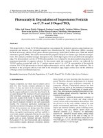
Fig.
1.
Schematic
view
of
the
viscous
flow
ALD
reactor
used
for
these
studies.
In
one
ALD
cycle,
two
co-reactants
(e.g.
diethyl
zinc
and
water
for
ZnO
formation)
are
introduced
alternatively,
with
an
inert
gas
purge
step
in
between,
allowing
forma-
tion
of
one
atomic
layer
of
ZnO.
Desired
thickness
could
be
achieved
by
repeating
the
ALD
cycles.
oxide
thin
film
coatings
on
high
aspect
ratio
polymer
fiber
sub-
strates
[20–26].
Some
of
these
reports
also
show
photocatalytic
performance
of
the
resulting
polymer/oxide
structures
[24,25].
For
this
study,
we
show
that
the
ALD
coating
provides
an
ideal
seed
layer
for
hydrothermal
growth
of
ZnO
nanorod
crystals
on
fiber
substrates,
and
that
these
nanocrystal-coated
fibers
show
high
pho-
tocatalytic
activity
compared
to
previous
structures.
In
particular,
we
describe
an
ALD
process
to
deposit
a
thin
layer
of
ZnO
onto
a
polybutylene
terephthalate
(PBT)
nonwoven
fiber
mat,
where
the
ZnO
layer
is
then
used
as
a
seed
layer
for
low
tem-
perature
ZnO
nanorod
hydrothermal
growth
[16].
This
sequence
creates
a
hierarchical
fiber/nanorod
crystal
composition
with
surface-normal
ZnO
nanorods
on
the
cylindrical
fiber
template.
The
final
fiber
cross-section
was
imaged
and
physically
characterized,
and
the
photocatalytic
properties
of
the
fiber/nanorod
construc-
tion
were
tested
and
compared
to
uncoated
fibers
and
to
fibers
uniformly
coated
with
ZnO
ALD
(i.e.
without
the
hydrothermal
growth
step).
The
hierarchical
structure
shows
superior
photocat-
alytic
performance,
consistent
with
the
expected
enhanced
surface
area.
2.
Experimental
procedures
2.1.
ZnO
seed
layer
deposition
by
ALD
The
substrate
for
ZnO
nanocrystal
growth
was
a
multilayered
nonwoven
PBT
fiber
mat
acquired
from
the
Nonwoven
Cooperative
Research
Center
(NCRC)
at
NC
State
University.
Electron
microscopy
images
of
the
PBT
mats
showed
that
they
were
a
mass
of
individual
fibers
(2–3
m
in
diameter)
with
a
total
mat
thickness
of
∼0.5
mm
[27].
We
monitored
ALD
growth
by
depositing
simultaneously
onto
polished
silicon
wafer
pieces.
Fig.
1
displays
a
schematic
drawing
of
the
homemade
viscous
flow
hot
wall
vacuum
reactor
used
for
zinc
oxide
ALD
[28].
The
reaction
system
is
composed
of
stainless
steel
tube
∼3.5
cm
in
diameter,
surrounded
by
a
heating
jacket
to
con-
trol
the
reactor
temperature
(100
◦
C
for
these
studies).
The
carrier
gas
was
ultrahigh-purity
Ar
(99.999%
National
Welders)
flowing
at
∼200
standard
cubic
centimeters
per
minute
(sccm).
The
reac-
tion
system
was
pumped
using
a
rotary
mechanical
pump,
and
the
steady-state
process
pressure
was
∼1.0
Torr,
as
monitored
by
a
Baratron
pressure
gauge
(MKS
Instrument
Inc.).
One
ZnO
ALD
cycle
consisted
of
a
2
s
exposure
to
diethyl
zinc
(DEZ,
98%
Strem
Chemi-
cal)
followed
by
a
60
s
Ar
purge,
a
2
s
water
exposure,
and
another
60
s
Ar
purge
(the
sequence
is
denoted
as
2/60/2/60
s).
The
reactant
pulse
produced
a
pressure
increase
of
50
mTorr
in
the
reactor.
The
seed
layers
were
deposited
using
either
100
or
200
ZnO
deposi-
tion
cycles,
which
produce
∼20
or
40
nm
thick
films,
respectively,
on
planar
silicon
substrates.
Refractive
index
and
film
thickness
on
silicon
was
measured
by
variable-angle
alpha-SE
spectroscopic
ellipsometry
(J.A.
Woollam
Co.,
Inc.).
2.2.
Hydrothermal
growth
of
ZnO
nanorod
crystals
on
seed
layer
After
ALD
coating,
the
PBT
fibers
and
silicon
control
wafer
were
transferred
into
a
teflon
vessel
containing
30
ml
aqueous
solution
of
equimolar
(20
mM)
zinc
nitrate
hexahydrate
(Zn(NO
3
)
2
·6H
2
O,
99%
Aldrich)
and
hexamethylene
tetramine
(C
6
H
12
N
4
,
99%
Aldrich).
The
vessel
was
left
open
and
held
in
an
oven
at
80
◦
C
for
6
h
resulting
in
the
growth
of
ZnO
nanorod
crystals
on
the
ZnO
coated
silicon
and
PBT
substrates.
The
silicon
wafer
was
held
face-down
in
the
solution
to
prevent
the
precipitation
of
any
ZnO
particles
that
may
have
formed
in
the
solution
bulk.
After
growth,
the
PBT
fiber
mat
and
Si
wafer
were
rinsed
with
deionized
water
for
2
min,
and
then
dried
in
N
2
flow
at
room
temperature.
Seed
layer
thicknesses
of
∼20
and
40
nm
were
investigated.
2.3.
Microscopy
and
surface
analysis
The
microstructure
of
the
modified
fibers
was
analyzed
using
an
FEI
XL30
Scanning
Electron
Microscope
(SEM)
operating
at
7
kV
with
a
working
distance
of
5
mm.
Before
SEM
imaging,
samples
sputter-coated
with
5
nm
of
Au/Pd
to
reduce
surface
charging.
Transmission
Electron
Microscope
(TEM)
images
of
ZnO
nanorod
crystals
on
polymer
fiber
mats
were
collected
using
a
Hitachi
HF
cold
field
emission
TEM
operated
at
200
kV
with
0.2
nm
point
res-
olution.
The
TEM
samples
were
prepared
by
heating
the
treated
fiber
at
400
◦
C
in
air
for
24
h,
resulting
in
calcination
of
the
poly-
mer.
After
calcination,
the
resulting
materials
were
dispersed
in
methanol,
sonicated
for
1
min,
and
then
transferred
by
pipette
onto
carbon
film-coated
TEM
grids
(Ted
Pella,
Inc.).
The
static
water
contact
angle
on
the
starting
and
modified
sur-
faces
was
collected
using
a
Model
200
Rame
Hart
contact
angle
goniometer
equipped
with
a
CCD
camera.
We
measured
at
least
five
different
points
on
each
sample
and
the
average
value
is
reported.
A
Quantachrome
Autosorb-1C
surface
area
and
pore
size
ana-
lyzer
provided
information
on
the
Brunauer
Emmett
Teller
(BET)
surface
area
of
the
materials
before
and
after
processing.
Before
each
analysis,
samples
were
heated
under
vacuum
at
100
◦
C
for
at
least
4
h
to
remove
residual
and
moisture
adsorbed.
The
recorded
data
was
collected
from
∼200
mg
samples
using
a
seven
point
BET
(P/P
0
range
from
0.05
to
0.35)
analysis.
2.4.
Photocatalytic
characterization
Fiber
samples
with
ZnO
ALD
coating,
ZnO
coating
with
sub-
sequent
hydrothermal
nanocrystal
growth,
as
well
as
untreated
fibers
were
all
cut
into
uniform
sample
pieces
(1.8
cm
×
1.8
cm)
and
placed
into
three
glass
vials,
each
containing
25
ml
of
deionized
water
with
equal
concentrations
(3
×
10
−4
vol.%)
of
commercially
available
azo
acid
red
40
dye.
We
then
exposed
the
vial
(uncapped)
to
UV
radiation
from
a
shuttered
Intell-Ray
400
Uvitron
Inter-
national
UV
floodlight
(320–390
nm)
providing
79
mW/cm
2
of
energy
flux
impinging
from
the
top.
The
incident
power
density
was
determined
using
a
1916-C
Newport
optical
power
meter.
By
monitoring
the
concentration
of
the
dye
in
the
vessel
by
UV–vis
absorbance
(measured
by
a
Thermo
Scientific
Evolution
300
UV-
Vis
spectrophotometer)
as
a
function
of
time,
we
were
able
to
quantify
the
relative
rate
of
dye
degradation
and
hence
analyze
the
effective
photocatalytic
activity
of
the
different
prepared
sam-
ples.
3.
Results
and
discussion
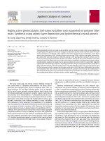
Fig.
2
presents
SEM
images
of
silicon
wafers
after
hydrother-
mal
ZnO
nanorod
crystal
growth.
The
sample
in
panels
(a)
and
(b)
is
prepared
by
hydrothermal
growth
directly
on
the
silicon
wafer
B.
Gong
et
al.
/
Applied
Catalysis
A:
General
407 (2011) 211–
216 213
Fig.
2.
Scanning
electron
microscopy
images
of
silicon
wafers
after
ZnO
hydrothermal
growth.
Images
(a)
and
(b)
were
collected
from
samples
without
an
ALD
ZnO
nucleation
layer.
Alternatively,
images
(c)
and
(d)
were
from
silicon
samples
that
were
coated
with
100
cycles
of
ALD
ZnO
before
hydrothermal
ZnO
nanorod
crystal
growth.
(i.e.
without
the
ZnO
ALD
seed
layer),
and
the
images
in
panels
(c)
and
(d)
were
collected
from
a
silicon
wafer
with
the
ALD
ZnO
seed
layer.
Without
the
seed
layer,
only
small
amount
of
sparsely
distributed
ZnO
nanocrystals
are
present.
They
are
also
relatively
large
(∼1
m
in
diameter
and
∼3–5
m
long).
When
the
substrate
is
pre-coated
with
100
ZnO
ALD
cycles
(producing
a
seed
layer
∼20
nm
thick,
as
determined
by
ellipsometry),
the
hydrothermal
growth
step
yields
complete
coverage
of
ZnO
nanorod
crystals
with
uniform
size
of
∼50
nm
diameter
and
∼500
nm
long.
We
also
note
that
the
nanorods
show
predominantly
surface-normal
orientation,
whereas
more
random
orientation
is
produced
without
the
seed
layer.
The
ALD
ZnO
provides
a
good
seed
layer
for
the
hydrother-
mal
growth
of
ZnO
nanocrystals.
The
detailed
ALD
condition
could
change
the
surface
roughness
of
the
PBT
fiber
mat,
and
further
affect
the
morphology
of
coated
ZnO
nanorods.
The
effects
of
ZnO
ALD
seeding
were
also
tested
on
polymer
fiber
mat.
Fig.
3
presents
SEM
images
of
PBT
nonwoven
fiber
mats
after
ZnO
nanorod
crystal
growth.
For
the
bare
PBT
fiber
mat,
the
images
in
Fig.
3(a)
and
(b)
show
only
sparse
and
relatively
large
ZnO
clus-
ters,
similar
to
growth
on
untreated
silicon
wafer.
Fig.
3(c)
and
(d)
shows
a
PBT
fiber
mat
after
20
nm
(100
cycles)
of
ALD
ZnO
followed
by
hydrothermal
growth.
Interestingly,
ZnO
nanocrystals
only
grow
on
the
outer
surface
of
the
substrate
mat,
and
fibers
in
the
middle
layers
of
the
substrate
show
almost
no
nanocrystal
growth.
This
non-uniformity
is
particularly
visible
in
Fig.
3(d),
in
which
fibers
at
the
top
of
the
mat
appear
to
have
a
much
larger
diameter
because
of
the
nanorod
crystals.
To
understand
this
non-uniformity
in
nanorod
growth,
we
examined
water
droplet
contact
angle
and
water
penetration
into
the
nonwoven
fiber
mat
after
the
ALD
coating
[22].
As
received,
the
PBT
fibers
appear
hydrophobic.
A
water
droplet
placed
on
the
fiber
mat
did
not
absorb
and
the
average
static
water
contact
angle
was
∼120
◦
.
After
coating
the
mat
with
100
cycles
of
ZnO
ALD,
water
still
did
not
readily
penetrate,
and
the
contact
angle
was
∼100
◦
.
We
believe
that
the
hydrophobic
nature
of
the
coated
PBT
fiber
mat
limits
the
penetration
of
the
aqueous
hydrothermal
process
solution
into
the
mat,
resulting
in
hydrothermal
growth
primarily
on
the
outer
fibers,
as
shown
in
Fig.
3(c)
and
(d).
We
find,
however,
that
after
200
cycles
of
ZnO
ALD,
the
PBT
fiber
mat
became
com-
pletely
wetting
(contact
angle
∼0
◦
),
which
will
readily
allow
the
aqueous
hydrothermal
solution
to
penetrate
into
the
matrix.
This
wetting
transition
for
ALD
coated
polymer
fibers
has
been
previ-
ously
observed,
and
it
is
understood
to
result
from
a
combination
of
changes
in
surface
chemical
termination
and
surface
roughness
[22].
As
demonstrated
in
Fig.
3(e)
and
(f)
PBT
fiber
samples
coated
with
200
cycles
ALD
ZnO
as
a
seed
layer
yielded
a
uniform
coating
of
ZnO
nanorod
crystals
deeper
into
the
fiber
mat.
Several
sample
fibers
extracted
at
random
from
the
bulk
of
the
mat
were
examined
by
SEM,
and
all
showed
good
coverage
of
ZnO
nanocrystals
after
the
hydrothermal
growth
with
small
variation
in
number
and
density
of
the
crystallites.
High
resolution
TEM
images
presented
in
Fig.
4
show
nanorod
crystals
grown
on
PBT
using
the
200
cycles
ZnO
ALD
seed
lay-
ers.
The
PBT
fiber
has
been
removed
by
a
calcination
step
at
400
◦
C
for
24
h.
Fig.
4(a)
clearly
shows
both
the
oriented
ZnO
nanorod
crystals
and
the
ZnO
shell
layer.
The
lattice
fringe
spacing
of
∼0.32
nm
measured
in
Fig.
4(b)
confirms
the
ZnO
wurtzite
structure.
The
hydrothermal
process
likely
produces
zincite
[29]
which
transforms
to
wurtzite
during
the
relative
high
temperature
calcination
step.
The
particular
sample
shown
in
Fig.
4
reveals
a
smaller
number
of
nanocrystals.
This
could
result
from
damage
during
sonication
for
the
TEM
sample
214 B.
Gong
et
al.
/
Applied
Catalysis
A:
General
407 (2011) 211–
216
Fig.
3.
Scanning
electron
micrographs
obtained
from:
(a)
and
(b)
untreated
PBT
fibers
after
hydrothermal
ZnO
nanorod
crystal
growth;
(c)
and
(d)
PBT
fibers
after
100
ALD
cycles
of
ZnO
(∼20
nm
thick),
followed
by
hydrothermal
ZnO
nanorod
growth.
Nanorod
crystals
are
visible
primarily
on
the
top-most
fibers
in
the
fiber
mat.
Panels
(e)
and
(f)
show
PBT
fibers
after
200
cycles
(∼40
nm)
of
ALD
ZnO,
followed
by
ZnO
nanorod
growth.
Nanorod
growth
is
visible
on
all
the
fibers.
In
panel
(b)
a
circle
highlights
a
large
crystal,
similar
in
size
to
the
one
shown
in
Fig.
2(b),
formed
on
the
untreated
fiber.
preparation,
or
some
non-uniformity
in
the
hydrothermal
growth
step.
The
surface
area
is
critical
for
the
catalytic
performance
of
ZnO
structures.
The
BET
surface
area
measured
by
nitrogen
adsorption/
desorption
analysis
was
∼0.73
m
2
/g
for
the
untreated
PBT
fiber
mat,
with
a
factor
of
2–3
increase
in
surface
area
to
∼1.79
m
2
/g,
after
the
ZnO
seed
layer
and
hydrothermal
growth.
This
increase
is
rather
modest
on
a
per
mass
basis.
However,
we
note
that
after
hydrother-
Fig.
4.
Transmission
electron
microscopy
images
obtained
from
ZnO
nanorod
crystals
on
PBT
fibers
where
the
polymer
was
removed
by
calcination
before
imaging.
In
image
(a),
the
nanorods
are
visible
protruding
from
the
ZnO
thin
film
layer
that
remains
after
calcination.
The
arrow
on
the
left
in
image
(a)
points
to
a
region
of
ALD
ZnO
coating
without
nanorod
crystal
growth.
The
image
in
(b)
was
collected
from
the
tip
of
a
nanocrystal
rod,
as
indicated
by
the
region
circled
in
(a).
The
HRTEM
image
shows
the
lattice
spacing
is
0.32
nm,
indicating
wurtzite
ZnO.
B.
Gong
et
al.
/
Applied
Catalysis
A:
General
407 (2011) 211–
216 215
Fig.
5.
Normalized
absorbance
of
organic
dye
at
525
nm
plotted
versus
UV
radiation
exposure
time.
PBT
fiber
substrates
with
various
surface
treatments
were
immersed
in
the
aqueous
solution
containing
the
azo
dye
(acid
red
40),
and
illuminated
using
a
UV
lamp.
The
fibers
with
ALD
ZnO
and
ZnO
nanorod
crystals
produced
the
most
rapid
photocatalytic
dye
degradation.
The
inset
shows
a
photograph
of
the
dye
solutions
in
contact
with
the
different
substrates
after
2
h
of
illumination.
The
red
dye
is
nearly
completely
removed
from
the
solution
in
contact
with
the
nanorod-coated
fibers.
mal
growth,
the
net
mass
(per
cm
2
of
fiber
mat
sample)
increased
by
a
factor
of
four
compared
to
the
sample
with
ALD
ZnO
coating,
which
verifies
a
significant
amount
of
hydrothermal
ZnO
deposi-
tion.
The
increase
in
mass,
combined
with
an
increase
in
surface
area
per
unit
mass
basis
means
that
on
a
per
sample
basis
(i.e.
for
a
fixed
fiber
mat
sample
size),
the
surface
area
of
the
fiber
mat
increases
by
at
least
a
factor
of
10
compared
to
the
starting
sample.
An
even
larger
increase
in
surface
area
could
be
expected
if
a
fiber
mat
support
with
finer
fibers
was
used,
or
if
thinner
and/or
longer
nanorods
could
be
grown.
The
density
and
porosity
of
the
fiber
mat
also
likely
play
a
role
in
determining
the
optimum
conditions
to
achieve
uniform
nanocrystal
growth
and
high
surface
area.
An
organic
dye
in
aqueous
solution
was
used
to
test
the
pho-
tocatalytic
performance
of
ZnO
functionalized
PBT
fiber
mats.
The
photocatalytic
decomposition
of
organic
materials
in
aqueous
solu-
tion
is
generally
believed
to
be
initiated
by
photo-excitation
of
ZnO,
producing
hydroxyl
radicals
and
holes
with
high
oxidative
potential,
permitting
rapid
oxidation
of
organics
in
contact
with
the
surface
[5,7].
Fig.
5
shows
the
photocatalytic
performance
of
ZnO
treated
fiber
mat
samples
where
the
UV–vis
absorbance
measured
at
525
nm,
normalized
to
the
starting
absorbance
of
each
dye
solution
sample,
is
plotted
versus
UV
exposure
time.
Upon
UV
irradiation,
the
dye
degraded
in
all
sample
vials,
but
the
sample
vial
containing
the
nanocrystal-coated
fibers
in
con-
tact
with
the
solution
showed
a
substantially
faster
degradation
rate
compared
with
the
other
samples.
In
addition,
we
performed
a
control
experiment
without
UV
exposure
where
a
similar
sized
nanocrystal-coated
PBT
fiber
mat
was
placed
into
the
dye
solution
and
kept
in
dark
for
2
h.
As
expected,
negligible
UV–vis
absorbance
change
was
observed
from
the
dye
solution,
which
confirmed
that
the
decomposition
is
photocatalytic.
Additionally,
dye
solutions
with
and
without
the
untreated
PBT
fiber
mat
showed
only
lim-
ited
absorbance
change
under
UV
exposure,
confirming
that
the
fibers
themselves
do
not
lead
to
dye
degradation
[30].
However,
we
find
that
the
conformal
ZnO
coating
on
the
fibers
(without
nanorod
growth)
is
sufficient
to
catalyze
some
UV
degradation
of
the
dye.
The
inset
includes
images
of
three
solution
vials
after
a
total
of
2
h
UV
exposure.
The
vial
containing
the
control
PBT
fiber
shows
little
degradation,
and
the
vial
with
ALD
ZnO
coated
PBT
shows
improved
degradation
compared
to
the
vial
with
the
uncoated
PBT
substrate.
The
vial
containing
the
PBT
with
ALD
ZnO
and
nanorod
crystals
showed
the
best
performance,
degrading
∼90%
of
the
dye
Fig.
6.
Reusability
of
ZnO
treated
PBT
fiber
mat
for
photocatalytic
dye
degradation.
For
the
PBT
fiber
mats
coated
with
ALD
ZnO
and
with
ALD
ZnO
+
nanorods
both
showed
repeatable
photocatalytic
degradation
performance
over
three
consecutive
2-h
exposure
runs.
The
slight
decrease
in
photocatalytic
efficiency
for
each
sample
is
ascribed
to
surface
contamination
that
accumulated
during
testing.
within
2
h.
This
superior
performance
is
ascribed
to
the
larger
solu-
tion/photocatalyst
contact
area
for
the
ALD/hydrothermal
prepared
materials.
The
reusability
of
the
ZnO
coated
PBT
fiber
mats
for
photocat-
alytic
dye
decomposition
was
also
tested.
Fig.
6
displays
results
of
three
degradation
tests
performed
in
sequence
using
ALD
ZnO-
coated
PBT
fibers,
and
using
similar
samples
coated
further
with
ZnO
nanorods.
both
types
of
samples
showed
repeatable
photo-
catalytic
activity
towards
acid
dye
degradation,
where
again,
the
samples
with
nanorods
show
more
rapid
dye
dissociation.
We
note
that
after
each
run,
samples
were
transferred
directly
into
a
fresh
fluid
sample
without
surface
cleaning
or
other
treatment,
so
the
decreased
reaction
rate
during
the
second
and
third
runs
is
likely
due
to
surface
contamination
accumulated
during
the
previous
test.
We
also
performed
side-by-side
comparisons
of
the
same
mate-
rial
sets
using
sunlight
illumination
in
place
of
the
laboratory
UV
lamp.
While
degradation
under
sunlight
was
less
rapid
than
for
the
UV
lamp,
the
experiment
produced
the
same
trend
in
pho-
tocatalytic
performance.
The
fibers
with
nanorod
crystals
present
showed
substantially
more
degradation
with
the
same
expo-
sure
time.
The
integrated
ALD/hydrothermal
deposition
method
described
here
demonstrated
an
efficient
way
to
further
improve
photocatalytic
materials,
and
it
would
be
a
viable
method
to
enhance
other
photoactive
surface
processes.
4.
Summary
and
conclusions
Photocatalytically
active
ZnO
nanorod
crystals
are
readily
grown
using
a
low
temperature
hydrothermal
procedure
on
PBT
fibers
mats,
when
the
fibers
are
first
coated
with
a
conformal
ZnO
nucleation
layer
using
atomic
layer
deposition.
The
ALD
efficiently
functionalized
the
polymer
fiber
to
facilitate
hydrothermal
nanorod
crystal
nucleation
and
subsequent
growth.
The
process
produces
fibers
with
∼10×
enhancement
in
total
surface
area
(determined
from
BET
analysis)
on
a
per
sample
size
(cm
2
/cm
2
)
basis.
We
demonstrated
that
the
ZnO
film/nanorod
composite
will
photocat-
alytically
degrade
an
azo
organic
dye
(acid
red
40)
in
aqueous
media
at
a
rate
that
is
nearly
2×
faster
than
a
similar
fiber
with
only
the
ZnO
film
coating.
This
2×
rate
enhancement
is
less
than
the
10×
sur-
face
area
increase,
probably
because
of
shadowing
effects
during
illumination.
More
importantly,
the
functionalized
polymer
fiber
mat
could
be
reused
very
easily,
and
no
additional
particle
recov-
ery
process
is
needed.
This
combination
of
ALD
and
hydrothermal
216 B.
Gong
et
al.
/
Applied
Catalysis
A:
General
407 (2011) 211–
216
processes
may
also
be
useful
for
other
crystal
growth
systems,
such
as
TiO
2
,
Fe
2
O
3
,
SnO
2
and
V
2
O
5
,
where
high
area
and
ready
solution
access
are
desired.
Acknowledgement
We
acknowledge
support
for
this
work
from
the
US
National
Science
Foundation
under
grant
CBET-1034374.
References
[1]
M.
Law,
L.E.
Greene,
J.C.
Johnson,
R.
Saykally,
P.D.
Yang,
Nat.
Mater.
4
(2005)
455.
[2]
S.
Liang,
H.
Sheng,
Y.
Liu,
Z.
Huo,
Y.
Lu,
H.
Shen,
J.
Cryst.
Growth
225
(2001)
110.
[3]
H.
Ohta,
K.
Kawamura,
M.
Orita,
M.
Hirano,
N.
Sarukura,
H.
Hosono,
Appl.
Phys.
Lett.
77
(2000)
475.
[4] J.
Zhang,
L.D.
Sun,
H.Y.
Pan,
C.S.
Liao,
C.H.
Yan,
New
J.
Chem.
26
(2002)
33.
[5]
N.
Daneshvar,
D.
Salari,
A.R.
Khataee,
J.
Photochem.
Photobiol.
A:
Chem.
162
(2004)
317.
[6]
B.
Pal,
M.
Sharon,
Mater.
Chem.
Phys.
76
(2002)
82.
[7] C.S.
Turchi,
D.F.
Ollis,
J.
Catal.
122
(1990)
178.
[8]
L.E.
Greene,
M.
Law,
J.
Goldberger,
F.
Kim,
J.C.
Johnson,
Y.F.
Zhang,
R.J.
Saykally,
P.D.
Yang,
Angew.
Chem.
Int.
Ed.
42
(2003)
3031.
[9]
Y.
Li,
G.W.
Meng,
L.D.
Zhang,
F.
Phillipp,
Appl.
Phys.
Lett.
76
(2000)
2011.
[10] J.J.
Wu,
S.C.
Liu,
Adv.
Mater.
(Weinheim,
Germany)
14
(2002)
215.
[11]
L.F.
Xu,
Q.
Liao,
J.P.
Zhang,
X.C.
Ai,
D.S.
Xu,
J.
Phys.
Chem.
C
111
(2007)
4549.
[12]
M.S.
Arnold,
P.
Avouris,
Z.W.
Pan,
Z.L.
Wang,
J.
Phys.
Chem.
B
107
(2003)
659.
[13]
Z.R.
Dai,
Z.W.
Pan,
Z.L.
Wang,
Adv.
Funct.
Mater.
13
(2003)
9.
[14]
Y.H.
Tong,
Y.C.
Liu,
C.L.
Shao,
R.X.
Mu,
Appl.
Phys.
Lett.
88
(2006)
123111.
[15]
L.
Vayssieres,
K.
Keis,
S.E.
Lindquist,
A.
Hagfeldt,
J.
Phys.
Chem.
B
105
(2001)
3350.
[16]
J S.
Na,
B.
Gong,
G.
Scarel,
G.N.
Parsons,
ACS
Nano
3
(2009)
3191.
[17]
E.
Santala,
M.
Kemell,
M.
Leskela,
M.
Ritala,
Nanotechnology
20
(2009)
035602.
[18] X.Y.
Zhang,
J.Y.
Dai,
H.C.
Ong,
N.
Wang,
H.L.W.
Chan,
C.L.
Choy,
Chem.
Phys.
Lett.
393
(2004)
17.
[19] R.B.M.
Cross,
M.M.
De
Souza,
E.M.S.
Narayanan,
Nanotechnology
16
(2005)
2188.
[20] G.K.
Hyde,
K.J.
Park,
S.M.
Stewart,
J.P.
Hinestroza,
G.N.
Parsons,
Langmuir
23
(2007)
9844.
[21] G.K.
Hyde,
G.
Scarel,
J.C.
Spagnola,
Q.
Peng,
K.
Lee,
B.
Gong,
K.G.
Roberts,
K.M.
Roth,
C.A.
Hanson,
C.K.
Devine,
S.M.
Stewart,
D.
Hojo,
J.S.
Na,
J.S.
Jur,
G.N.
Parsons,
Langmuir
26
(2010)
2550.
[22]
M.
Kemell,
V.
Pore,
M.
Ritala,
M.
Leskela,
M.
Linden,
J.
Am.
Chem.
Soc.
127
(2005)
14178.
[23]
Q.
Peng,
X.Y.
Sun,
J.C.
Spagnola,
G.K.
Hyde,
R.J.
Spontak,
G.N.
Parsons,
Nano
Lett.
7
(2007)
719.
[24] M.
Kemell,
V.
Pore,
M.
Ritala,
M.
Leskela,
Chem.
Vap.
Deposition
12
(2006)
419.
[25]
S.M.
Lee,
G.
Grass,
G.M.
Kim,
C.
Dresbach,
L.B.
Zhang,
U.
Gosele,
M.
Knez,
Phys.
Chem.
Chem.
Phys.
11
(2009)
3608.
[26]
S.M.
Lee,
E.
Pippel,
U.
Gosele,
C.
Dresbach,
Y.
Qin,
C.V.
Chandran,
T.
Brauniger,
G.
Hause,
M.
Knez,
Science
324
(2009)
488.
[27]
B.
Gong,
Q.
Peng,
J.S.
Jur,
C.K.
Devine,
K.
Lee,
G.N.
Parsons,
Chem.
Mater.
23
(2011)
3476.
[28]
B.
Gong,
Q.
Peng,
G.N.
Parsons,
J.
Phys.
Chem.
B
115
(2011)
5930.
[29]
C.
Hariharan,
Appl.
Catal.
A:
Gen.
304
(2006)
55.
[30]
P.
Gijsman,
G.
Meijers,
G.
Vitarelli,
Polym.
Degrad.
Stab.
65
(1999)
433.