Giáo trình vi xử lý - Beginning Microcontrollers with the MSP430
Bạn đang xem bản rút gọn của tài liệu. Xem và tải ngay bản đầy đủ của tài liệu tại đây (1.31 MB, 112 trang )
Beginning Microcontrollers
with the
MSP430
Tutorial
Gustavo Litovsky
Version 0.4
i
ii
This document is distributed in the hope that it will be useful, but WITHOUT ANY WARRANTY;
without even the implied warranty of MERCHANTABILITY or FITNESS FOR A PARTICULAR
PURPOSE.
You May copy, transmit and distribute this document to anyone provided you attribute it
to Gustavo Litovsky and the copyright notice remains. If you wish to use any part of the
document for commercial purposes, please contact me at gustavo [at] glitovsky [dot] com
All Trademarks are the properties of their respective owners.
Original copies of this docment are located at
www.glitovsky.com
iii
What’s new in this version?
Version 0.4
• A new chapter on Flash
Version 0.3
• A major update to the UART section describing more in detail how to configure the interface,
including an algorithm on accurately calculating the registers. Also included are details on
communicating with the Host PC such as framing.
• More information about the selection and use of crystals with the MSP430 and other micro-
controllers
• Major editing improvements that better convey the information
iv
Preface
I decided to write this tutorial after seeing many students struggling with the concepts of program-
ming the MSP430 and being unable to realize their applications and projects. This was not because
the MSP430 is hard to program. On the contrary, it adopts many advances in computing that has
allowed us to get our application running quicker than ever. However, it is sometimes difficult for
students to translate the knowledge they acquired when studying programming for more traditional
platforms to embedded systems.
Programming for embedded systems (as is the case with the MSP430) is not more difficult than
personal computers. In fact, it is much better in that it exposes us to the little details of how the
system operates (the clocks, I/O) at a level that anyone can learn, as well as unparalleled flexibility.
This, however, also forces us to make critical decisions that affect how the application runs.
The MSP430 microcontroller is an extremely versatile platform which supports many applications.
With its ultra low power consumption and peripherals it enables the designing engineer to meet the
goals of many projects. It has, of course, its limitations. It is geared mostly towards low energy
and less intensive applications that operate with batteries, so processing capabilities and memory,
among other things, are limited.
This tutorial will begin from the basics, introducing you to the theory necessary to manipulate
binary digits and digital logic as used in the microcontroller. Using this you will be able to see
how to manipulate the registers which control the operation of all microcontrollers. It will then
cover the specifics of modules in the MSP430, from both the hardware and software perspective. I
decided to follow this format primarily because you, the reader, might want to use this tutorial as a
reference and just jump to a module you need help with. But I also wanted to keep the tutorial to
be accessible for beginners and so the first part of the tutorial covers many of the essentials.
If you wish to begin programming immediately and understand code, you could skip to Chapter
4. Previous knowledge of the C programming language is assumed, although if you’ve done some
Java programming, you will likely be familiar with the concepts. It is important to note that this
tutorial should be supplemented by the Datasheet, User’s Guide, Example Code and Application
Notes for the specific MSP430 derivative used and any other component in the system. These are
extremely useful in teaching you how to integrate all the ideas you have and apply them. All these
documents are freely available at www.TI.com Don’t Ignore them! They will answer many of your
questions.
A companion file is included . This code has two components. The first is straight C code primarily
based on the slaa325 application note from TI which was ported to the EZ430 and establishes very
basic communications. The second part is based upon the TI Sensor Demo Code for the EZ430-
RF2500.
v
vi Chapter 0 Preface
Contents
Preface v
1 Introduction 1
1.1 Why Microcontrollers? . . . . . . . . . . . . . . . . . . . . . . . . . . . . . . . . 1
1.2 What Hardware do I need? . . . . . . . . . . . . . . . . . . . . . . . . . . . . . . 1
1.2.1 EZ430-F2013 USB Stick Development Tool . . . . . . . . . . . . . . . . 2
1.2.2 EZ430-RF2500 . . . . . . . . . . . . . . . . . . . . . . . . . . . . . . . . 3
1.2.3 Experimenter Boards . . . . . . . . . . . . . . . . . . . . . . . . . . . . . 4
1.2.4 FET Debugger . . . . . . . . . . . . . . . . . . . . . . . . . . . . . . . . 4
1.2.5 Custom Hardware . . . . . . . . . . . . . . . . . . . . . . . . . . . . . . 4
2 Getting Started 7
2.1 Introduction . . . . . . . . . . . . . . . . . . . . . . . . . . . . . . . . . . . . . . 7
2.2 Running a Project using IAR . . . . . . . . . . . . . . . . . . . . . . . . . . . . . 8
2.3 Running a Project using CCS . . . . . . . . . . . . . . . . . . . . . . . . . . . . . 10
3 Microcontroller Basics 11
3.1 Data Types and Numeric Representation . . . . . . . . . . . . . . . . . . . . . . . 11
3.2 Hexadecimal for MSP430 . . . . . . . . . . . . . . . . . . . . . . . . . . . . . . . 12
3.2.1 Conversion of Numbers . . . . . . . . . . . . . . . . . . . . . . . . . . . 14
3.3 Digital Operations . . . . . . . . . . . . . . . . . . . . . . . . . . . . . . . . . . . 14
3.4 Manipulating Module Registers . . . . . . . . . . . . . . . . . . . . . . . . . . . 15
3.4.1 XOR Operator . . . . . . . . . . . . . . . . . . . . . . . . . . . . . . . . 20
3.5 ASCII . . . . . . . . . . . . . . . . . . . . . . . . . . . . . . . . . . . . . . . . . 21
3.6 Conclusion . . . . . . . . . . . . . . . . . . . . . . . . . . . . . . . . . . . . . . 21
4 Beginning Programming for MSP430 23
vii
viii CONTENTS
5 MSP430 Clocks 27
5.1 Introduction . . . . . . . . . . . . . . . . . . . . . . . . . . . . . . . . . . . . . . 27
5.2 Internal Oscillators . . . . . . . . . . . . . . . . . . . . . . . . . . . . . . . . . . 28
5.3 External Crystals . . . . . . . . . . . . . . . . . . . . . . . . . . . . . . . . . . . 28
5.4 Clock Sources . . . . . . . . . . . . . . . . . . . . . . . . . . . . . . . . . . . . . 30
5.5 Clock Signals . . . . . . . . . . . . . . . . . . . . . . . . . . . . . . . . . . . . . 30
5.6 Basic Clock Module In EZ430-RF2500 . . . . . . . . . . . . . . . . . . . . . . . 31
5.7 Considerations for using clocks . . . . . . . . . . . . . . . . . . . . . . . . . . . . 33
6 General Purpose Input Output - GPIO 35
6.0.1 Pin Multiplexing . . . . . . . . . . . . . . . . . . . . . . . . . . . . . . . 35
6.1 Switches . . . . . . . . . . . . . . . . . . . . . . . . . . . . . . . . . . . . . . . . 38
6.1.1 Debouncing . . . . . . . . . . . . . . . . . . . . . . . . . . . . . . . . . . 39
6.2 LEDs . . . . . . . . . . . . . . . . . . . . . . . . . . . . . . . . . . . . . . . . . 39
6.3 Bit banging . . . . . . . . . . . . . . . . . . . . . . . . . . . . . . . . . . . . . . 40
7 Flash Memory 41
7.1 Introduction . . . . . . . . . . . . . . . . . . . . . . . . . . . . . . . . . . . . . . 41
7.2 Flash and Memory Organization . . . . . . . . . . . . . . . . . . . . . . . . . . . 41
7.3 Looking at the Flash . . . . . . . . . . . . . . . . . . . . . . . . . . . . . . . . . 42
7.4 Programming the Flash . . . . . . . . . . . . . . . . . . . . . . . . . . . . . . . . 45
7.4.1 Configuring the Flash . . . . . . . . . . . . . . . . . . . . . . . . . . . . . 46
7.4.2 Reading the Flash . . . . . . . . . . . . . . . . . . . . . . . . . . . . . . . 47
7.4.3 Writing to Flash . . . . . . . . . . . . . . . . . . . . . . . . . . . . . . . 48
7.4.4 Finalizing Flash Access . . . . . . . . . . . . . . . . . . . . . . . . . . . 49
7.5 Flash Programming from the RAM . . . . . . . . . . . . . . . . . . . . . . . . . . 49
7.6 The Linker and Flash . . . . . . . . . . . . . . . . . . . . . . . . . . . . . . . . . 50
7.7 Using the Flash for data storage . . . . . . . . . . . . . . . . . . . . . . . . . . . 55
7.8 More Examples . . . . . . . . . . . . . . . . . . . . . . . . . . . . . . . . . . . . 55
8 Timers 57
8.1 Introduction . . . . . . . . . . . . . . . . . . . . . . . . . . . . . . . . . . . . . . 57
8.2 Setting up the clock . . . . . . . . . . . . . . . . . . . . . . . . . . . . . . . . . . 57
8.3 Timer Modes . . . . . . . . . . . . . . . . . . . . . . . . . . . . . . . . . . . . . 58
8.4 Accuracy . . . . . . . . . . . . . . . . . . . . . . . . . . . . . . . . . . . . . . . 58
CONTENTS ix
9 Interrupts and Low Power Modes 59
9.1 Interrupts . . . . . . . . . . . . . . . . . . . . . . . . . . . . . . . . . . . . . . . 59
9.2 Low Power Modes . . . . . . . . . . . . . . . . . . . . . . . . . . . . . . . . . . 65
9.2.1 Exiting Low Power Modes . . . . . . . . . . . . . . . . . . . . . . . . . . 67
10 Analog to Digital Converters - ADCs 69
10.1 Introduction . . . . . . . . . . . . . . . . . . . . . . . . . . . . . . . . . . . . . . 69
10.2 ADC Parameters . . . . . . . . . . . . . . . . . . . . . . . . . . . . . . . . . . . 70
10.2.1 ADC Resolution . . . . . . . . . . . . . . . . . . . . . . . . . . . . . . . 70
10.2.2 ADC Sampling Frequency . . . . . . . . . . . . . . . . . . . . . . . . . . 71
10.3 ADC Example - Temperature and Voltage . . . . . . . . . . . . . . . . . . . . . . 72
10.3.1 ADC Clock . . . . . . . . . . . . . . . . . . . . . . . . . . . . . . . . . . 73
10.3.2 ADC Modes . . . . . . . . . . . . . . . . . . . . . . . . . . . . . . . . . 73
11 Digital Interfaces 75
11.1 Serial Peripheral Interface (SPI) . . . . . . . . . . . . . . . . . . . . . . . . . . . 76
11.1.1 Configuring SPI . . . . . . . . . . . . . . . . . . . . . . . . . . . . . . . 77
11.1.2 Using SPI for Communications . . . . . . . . . . . . . . . . . . . . . . . 79
12 UART 81
12.1 Hardware Connection . . . . . . . . . . . . . . . . . . . . . . . . . . . . . . . . . 81
12.1.1 UART connectivity on the MSP430F1611 . . . . . . . . . . . . . . . . . . 81
12.1.2 UART connectivity on the MSP430F2274 . . . . . . . . . . . . . . . . . . 82
12.2 Using UART . . . . . . . . . . . . . . . . . . . . . . . . . . . . . . . . . . . . . 82
12.3 Configuring the UART . . . . . . . . . . . . . . . . . . . . . . . . . . . . . . . . 83
12.3.1 Selecting the UART Function for Pins . . . . . . . . . . . . . . . . . . . . 84
12.3.2 Enabling UART RX and TX . . . . . . . . . . . . . . . . . . . . . . . . . 84
12.3.3 Select the character format . . . . . . . . . . . . . . . . . . . . . . . . . . 84
12.3.4 Selecting A Clock . . . . . . . . . . . . . . . . . . . . . . . . . . . . . . 85
12.3.5 Setting the Baud Rate Generator . . . . . . . . . . . . . . . . . . . . . . . 86
12.3.6 Enabling the Module . . . . . . . . . . . . . . . . . . . . . . . . . . . . . 87
12.3.7 Enabling Interrupts . . . . . . . . . . . . . . . . . . . . . . . . . . . . . . 87
12.4 Configuring the Host Computer . . . . . . . . . . . . . . . . . . . . . . . . . . . . 88
12.5 Sending and Receiving Information with the UART . . . . . . . . . . . . . . . . . 88
12.5.1 Sending Bytes . . . . . . . . . . . . . . . . . . . . . . . . . . . . . . . . 88
x CONTENTS
12.5.2 ASCII . . . . . . . . . . . . . . . . . . . . . . . . . . . . . . . . . . . . . 89
12.6 Sending Multiple bytes . . . . . . . . . . . . . . . . . . . . . . . . . . . . . . . . 89
12.6.1 Sending Strings . . . . . . . . . . . . . . . . . . . . . . . . . . . . . . . . 90
12.7 Receiving Data . . . . . . . . . . . . . . . . . . . . . . . . . . . . . . . . . . . . 91
12.8 Framing . . . . . . . . . . . . . . . . . . . . . . . . . . . . . . . . . . . . . . . . 93
12.9 Future Additions . . . . . . . . . . . . . . . . . . . . . . . . . . . . . . . . . . . 95
13 Wireless Communications with CC2500 97
13.1 Introduction . . . . . . . . . . . . . . . . . . . . . . . . . . . . . . . . . . . . . . 97
13.2 SPI Interface . . . . . . . . . . . . . . . . . . . . . . . . . . . . . . . . . . . . . 98
List of Figures
1.1 EZ430-F2013 Development Stick . . . . . . . . . . . . . . . . . . . . . . . . . . 2
1.2 EZ430-RF2500 Development Stick . . . . . . . . . . . . . . . . . . . . . . . . . . 3
2.1 Creating a new empty project in IAR . . . . . . . . . . . . . . . . . . . . . . . . . 9
3.1 Converting Numbers Using the Windows Calculator . . . . . . . . . . . . . . . . . 14
3.2 ADC10 Register Example . . . . . . . . . . . . . . . . . . . . . . . . . . . . . . 16
5.1 Loading Capacitors on Crystal . . . . . . . . . . . . . . . . . . . . . . . . . . . . 28
5.2 Selecting the DCO Frequency . . . . . . . . . . . . . . . . . . . . . . . . . . . . 32
6.1 MSP430F2274 Schematic . . . . . . . . . . . . . . . . . . . . . . . . . . . . . . 35
6.2 Connecting Switches to MSP430 . . . . . . . . . . . . . . . . . . . . . . . . . . . 38
7.1 MSP430 Memory Organization Examples . . . . . . . . . . . . . . . . . . . . . . 42
7.2 MSP430 Memory after writing 0xAA in IAR . . . . . . . . . . . . . . . . . . . . 44
7.3 MSP430 Memory after writing 0xFF in IAR . . . . . . . . . . . . . . . . . . . . . 44
7.4 MSP430 Memory after writing 0x00 in IAR . . . . . . . . . . . . . . . . . . . . . 45
7.5 MSP430 Memory after writing 0xAA in CCS . . . . . . . . . . . . . . . . . . . . 46
9.1 Low Power Mode Savings . . . . . . . . . . . . . . . . . . . . . . . . . . . . . . 66
10.1 3-bit ADC Example . . . . . . . . . . . . . . . . . . . . . . . . . . . . . . . . . . 71
11.1 SPI Configurations . . . . . . . . . . . . . . . . . . . . . . . . . . . . . . . . . . 77
12.1 Connecting UART . . . . . . . . . . . . . . . . . . . . . . . . . . . . . . . . . . 82
12.2 UART Bits . . . . . . . . . . . . . . . . . . . . . . . . . . . . . . . . . . . . . . 83
xi
xii LIST OF FIGURES
List of Tables
3.1 Data Types . . . . . . . . . . . . . . . . . . . . . . . . . . . . . . . . . . . . . . 12
3.2 Hexadecimal Number System . . . . . . . . . . . . . . . . . . . . . . . . . . . . 12
3.3 Extended Hexadecimal vs. Binary and Decimal . . . . . . . . . . . . . . . . . . . 13
3.4 Digital Operations - OR and AND . . . . . . . . . . . . . . . . . . . . . . . . . . 14
3.5 Digital Operations - NOT and XOR . . . . . . . . . . . . . . . . . . . . . . . . . 15
3.6 Hexadecimal representation of position . . . . . . . . . . . . . . . . . . . . . . . 19
3.7 XOR Truth Table . . . . . . . . . . . . . . . . . . . . . . . . . . . . . . . . . . . 20
3.8 Extended Hexadecimal vs. Binary and Decimal . . . . . . . . . . . . . . . . . . . 21
11.1 SPI Signals . . . . . . . . . . . . . . . . . . . . . . . . . . . . . . . . . . . . . . 76
11.2 SPI Pins in the MSP430F2274 . . . . . . . . . . . . . . . . . . . . . . . . . . . . 78
xiii
xiv LIST OF TABLES
Chapter 1
Introduction
1.1 Why Microcontrollers?
To those who are unfamiliar with these devices, microcontrollers might seem extremely simple
and rare as compared to personal computers. However, microcontrollers and microprocessors are
embedded in many devices, with hundreds of them forming part of today’s automobile, control-
ling everything from the engine to the sound system. Cellular phones include more sophisticated
microprocessors, but these are not as different from the MSP430 that we will cover here in that
the basics apply to both. The power of microcontrollers lies in their small size and adaptability.
As opposed to fixed digital circuitry, microcontrollers can be programmed to perform many ap-
plications and can be later changed when improvement are required. This saves both time and
money when a field upgrade is required (which you will discover to be a grand objective of any
company). However, there are limitations with respect to processing power and memory (the two
biggest problems you face the use of embedded processors). It is the job of the engineer to come
up with the requirements of the application and select the proper device for the application. With
the advances in processing capability, many more applications can be realized today with micro-
controllers than ever before, especially due to their low power profile. Indeed, the flexibility of
these devices will ensure their incorporation in designs many years into the future.
It is important to note that a wide array of microcontrollers exist, some rivaling or surpassing
the capabilities of full fledged computers in the 70s, 80s, and maybe even 90s. UV Erasure of
microcontroller and ROM are today mostly a thing of the past. With the advent of Flash memory,
the microcontroller can be programmed hundred of thousands of times without any problems.
Also, they incorporate a wide array of modules such Analog to Digital Converters, USB, PWM,
and Wireless transceivers, enabling integration into any kind of application.
1.2 What Hardware do I need?
It is often the case students are confused about what exactly is needed for using a particular micro-
controller. Indeed, many companies assume everyone will understand the basics and therefore skip
this vital information. It used to be that companies provided the silicon (actual chip) and let the
1
2 Chapter 1 Introduction
application engineer sort out everything else. Today, most companies attempt to provide as much
information as possible to the developing engineer since most engineers want to get the application
working as soon as possible and avoid wasting time.
Normally, an embedded system is composed of the following:
• An Embedded Microcontroller
• A Programming/Debugging interface for the Microcontroller
• Microcontroller Support Circuitry
• Application Specific Circuitry
The Programming/Debugging interface is the most often ignored element of the system, but it is a
very important factor. Without it, how is code supposed to be put in the Microcontroller? With just
Programming capabilities, we can download a firmware image into the microcontroller. However,
Debugging is often a necessity since no person can write perfectly good code and ensure it can
run correctly. A common debugging interface is JTAG, which is often used in Microcontrollers.
The MSP430 also uses this interface,but TI adds extra functionality whose information is available
only under a Non Disclosure Agreement. Therefore, I would argue that selection of both the
debugger(or programmer) and even the compiler will dictate much of the effectiveness of the time
spent on the design. Do not settle for inferior tools! You will pay for them later in sweat and
suffering.
Today’s companies offer many platforms with which to develop and learn how to use their micro-
controller. Such is the case with TI. Some of their most useful development platforms are:
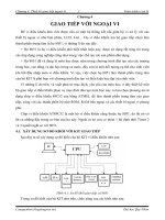
1.2.1 EZ430-F2013 USB Stick Development Tool
Figure 1.1: EZ430-F2013 Development Stick
This is one of the first MSP430 development tools to be in the USB stick form factor, which is
gaining popularity because it is so easy to use. Since it is very low cost($20)and has an integrated
debugger, it allows very quick development. It is composed of two boards (both located inside
the plastic casing): The programming board and the target board. The target board is the board
1.2 What Hardware do I need? 3
with the actual microcontroller (an MSP430F2013) and all the circuitry needed to use it. It can be
detached from the programmer once the software has been downloaded to the MSP430.
The debugger board, with its USB connector, can allow programming on any computer (although
there might be issues with a specific Operating System being unsupported). For more information,
see the following links:
EZ430-F2013 Home Page
MSP430F2013 Home Page
MSP430 Design Page - F2013 Contest
This last website has the EZ430 contest that can provide you with real insight as to what can be
done just with the EZ430.
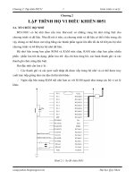
1.2.2 EZ430-RF2500
Figure 1.2: EZ430-RF2500 Development Stick
This development board is very similar to the regular EZ430 but includes a RF2500 transceiver and
a MSP430F2274 microcontroller (not the F2013). This is the kit that is the subject of this tutorials
because it delivers great value - microcontroller, transceiver and debugger - at a very low price
TI also supplies the sensor demo code which can be quickly programmed on both devices to enable
quick temperature monitoring. One target board has to be programmed with the End Device code
and the other with the Access Point code. The End device is the connected to the battery board
while the target board that has the Access Point software is left connected to the programmer board
and to the PC.
The sensor demo is simple. The End Device takes a reading of its Temperature Sensor (inte-
grated into the MSP430 and accessible as an ADC channel) and Voltage (the one applied to the
MSP430F2274). It sends this data to the Access Point, which also takes its own temperature and
voltage readings. The AP then integrates both of these and forwards them to the PC using the
UART. This data can be read using a hyperterminal equivalent program (Putty, a free program, is
recommended).
EZ430-RF2500 Home Page
4 Chapter 1 Introduction
1.2.3 Experimenter Boards
TI also provides more comprehensive boards, called Experimenter Boards. These are much larger
and don’t come with a built in Debugger. For that you need a FET Debugger(which is discussed
below). The two boards that are available are:
MSP430FG4618/F2013 Experimenter Board Home Page
MSP430F5438 Experimenter Board Home Page
Putty - Terminal Emulation Software Home Page
1.2.4 FET Debugger
To access the JTAG pins and debug the MSP430, TI provides a debugger, called a FET Debugger.
If you have purchased a board with a 14-pin JTAG connector, such as the experimenter boards or
many other boards by third parties, you will likely need this debugger.
There are two versions: one that connects a parallel port and another with USB connectivity.
The USB one is the most common one. This debugger allows step by step execution of code,
breakpoints, and other advanced things.
For more information:
MSP430 USB Debugging Interface Homepage
There are a few other debuggers out there, mostly sold by a company called Olimex and some
other third parties.
1.2.5 Custom Hardware
Most often, once you’ve developed your code and tested it on a development platform, you would
like to create your own PCB with the microcontroller The microcontroller itself is only an IC. It
requires several things to operate (which every development kit as mentioned above provides):
• Supply voltage consistent with Electrical Specifications (1.8V - 3.6V for most MSP430)
• Decoupling capacitors to reduce noise on the supply voltage (no power supply is perfect)
• External Crystals (in some cases where they are needed for the clock generation)
• A Programmer/Debugger or Bootstrap Loader
The list above provides the basic elements most microcontrollers need, which are besides the
specific parts and connections related to the application itself (such as sensors, transceivers, passive
components etc).
Users of the Microcontroller must ensure they provide the correct power supply. Although the
MSP430 family requires little current and thus can be operated by batteries or other low current
1.2 What Hardware do I need? 5
sources without any problems, it requires a specific voltage to be applied, and any deviation from
the Maximum Recommended Specifications (available in the datasheet) can destroy the IC. Mi-
crocontrollers such as those made by Microchip and Atmel usually can tolerate 5V (and in some
cases require it), but MSP430 generally accepts 1.8V to 3.6V, with possible damage to the IC when
the voltage is over 3.9V or so. It is essential that if you use your custom designed circuit for the
MSP430, you comply with the requirements set forth by the datasheet.
External Crystals should be used in applications that require more accuracy than is available from
the microcontroller. They add more size and cost, but enable more accurate clocks. Chapter 5
provides some more information about the clocks and crystals.
Most students are familiar with computers and how to program them, using a compiler to generate
the binary code and execute it. Microcontrollers, however, are different. They are programmed
with code produced by a special compiler in a computer. Once the code is compiled and linked, it
can be downloaded and debugged on the actual microcontroller (provided the interface to do so is
available). The MSP430 devices use an interface called JTAG to perform these functions. JTAG
allows a user to download and debug the code on the microcontroller, after being written with one
of the several compilers that are available. This interface is accessed by using a FET Programer
that connects the computer to the microcontroller. For MSP430 devices that do not have many pins
available, the programming interface available is called Spy-bi-Wire. This is proprietary to TI and
makes JTAG use 2 lines instead of the usual 4 or 5.
6 Chapter 1 Introduction
Chapter 2
Getting Started
2.1 Introduction
I hear and I forget; I see and I remember; I do and I understand.
- Old Chinese Proverb
As the chinese proverb indicates, doing is the best way of understanding. This chapter was created
to get you started compiling MSP430 programs, simply because it is the best way you will actully
learn and understand what this tutorial teaches. In order to compile MSP430 applications, an
MSP430 compiler is needed. There are several options:
• Code Composer Studio (CCS) - TI’s own MSP430 development suite that is also used for
many other TI devices. It is based on Eclipse and is a cost effective solution for development.
Currently it is in version 5.1.
Code Composer Studio for MSP430
• IAR Embedded Workbench for MSP430 - IAR is a well established company and its com-
piler is very good. It produces output code that is sometimes smaller and faster than others.
On the flip side, it is usually more expensive. A free version called the Kickstart edition
is provided that allows up to 4kB or 8kB of code depending on the MSP430 device used.
Another possibility is a 30-day Evaluation version that has no limitation.
IAR Embedded Workbench Kickstart for MSP430
• MSPGCC - A free MSP430 port of the well known GCC compiler. It requires some more
work to get going but is a very attractive option. It can be used for professional development.
MSPGCC Wiki
7
8 Chapter 2 Getting Started
If you are just beginning to program, I recommend that you get IAR Kickstart just to compile a
few programs. You can then move to CCS or MSPGCC.
2.2 Running a Project using IAR
I assume that you’ve installed IAR. This should be straightforward. IAR uses the concept of project
in a workspace. A workspace is simply a container of projects, and if you open IAR, a workspace is
already created for you. Workspaces are actual files with the extension
¨
’eww
¨
’. In order to compile,
link and debug MSP430 code, we must create a project. To do this, go to Project-¿ Create New
Project. Select MSP430 for the toolchain:
Once you press OK, you will be asked to save the project file. Please note that the file name
will also be the project’s name. Once the project is created, we must add the source code and
configure it. Since we have created an empty project, no files are incorporated. Press the
¨
New
Document
¨
button and IAR will open a new tab for a new file. save this file with the name
¨
main.c
¨
(the
actual name can be almost anything but it helps to make it obvious).
Copy paste the hello world source code below in main.c and save it:
Listing 2.1: MSP430 Hello World - hello world.c
1 #include "msp430x22x4.h"
2
3 volatile unsigned int i; // volatile to prevent optimization
4
5 void main(void)
6 {
7 WDTCTL = WDTPW + WDTHOLD; // Stop watchdog timer
8 P1DIR |= 0x01; // Set P1.0 to output direction
9
10 for (;;)
11 {
12 P1OUT ˆ= 0x01; // Toggle P1.0 using exclusive-OR
13 i = 50000; // Delay
14 do (i );
15 while (i != 0);
16 }
17 }
We will cover the actual operation of the code later, but this code simply blinks the LED on board.
Note that main.c is still not part of the project and cannot be compiled. To add it, right click on the
project name in the workspace window, go to Add and then Add
¨
main.c
¨
. Note that this only works
if main.c is the currently active tab. Else, select the Add files option and choose main.c.
We now need to configure the project options. To do this right click on the project name in the
workspace browser and go to Options. A window will appear. This window includes all the options
for the project. The most important one at the moment is to select the actual MSP430 device that
will be debugged. In the Device selection box there is a button, clicking on it shows a list of
MSP430 devices. Select here the MSP430 that you have on your board. ANother very important
aspect is to ensure that the FET Debugger is used. For this go to the Debugger in the list and
change ”‘Simulator”’ that appears as default to ”‘FET Debugger”’.
2.2 Running a Project using IAR 9
Figure 2.1: Creating a new empty project in IAR
If while debugging your application, the download of your application is very fast, you might be accidentally be using the Simulator. Many engineers have spent time
trying to figure out why their application wasn’t working only to discover that they were not actually downloading it to the board.
Once you’ve finished, press OK and close the options dialog. Then right click on the project and
press Rebuild all. IAR will compile and link the source code. You may then download and debug
using the CTRL+D shortcut.
IAR will automatically download the application and if everything is OK, will stop at the first line
of code. Pressing on the Go button will execute the code freely.
10 Chapter 2 Getting Started
2.3 Running a Project using CCS
During the CCS installation, you should have chosen to install support for the MSP430 and tue
USB FET device.
Similarly to IAR, CCS also has the concept of a workspace where projects are located, though
CCS uses Eclipse’s method of storing a workspace which is based on a folder with the information.
When you first open CCS, you’ll be asked to give the path to the workspace. This can be almost
any location. The first time CCS opens, it will request the mode in which you want to operate. The
Code Size limited option is good for starting and evaluating until you must move up because of the
code limitation. Once CCS opens, select the Project Menu and then New CCS Project. You can
put any valid Project name. Ensure that the device family is MSP430 and select the variant and
then the particular device. Finally select an Empty project.
CCS creates a new project and also a main.c file.
Copy paste the hello world source code below in main.c and save it:
Listing 2.2: MSP430 Hello World - hello world.c
1 #include "msp430x22x4.h"
2
3 volatile unsigned int i; // volatile to prevent optimization
4
5 void main(void)
6 {
7 WDTCTL = WDTPW + WDTHOLD; // Stop watchdog timer
8 P1DIR |= 0x01; // Set P1.0 to output direction
9
10 for (;;)
11 {
12 P1OUT ˆ= 0x01; // Toggle P1.0 using exclusive-OR
13 i = 50000; // Delay
14 do (i );
15 while (i != 0);
16 }
17 }
No configuration changes are needed. Simply go to Run-¿ Debug or press F11. A new debug
session will be open. You can then select run and the example will run.
Chapter 3
Microcontroller Basics
Microcontrollers are binary computers and so they operate on the basis of binary numbers. Binary
numbers consist of only 1 and 0. Binary, however, is unnatural for humans to use. Assembly lan-
guage is one step above binary. It is therefore the most basic language for controlling computers
since it represents binary directly and it is easier to understand. Knowledge of assembly is not
completely necessary to program the MSP430, but it is useful in optimizing routines to get the
maximum performance (in terms of speed or memory). The C programming language is the pri-
mary language used and will be followed throughout this tutorial. In general, a compiler translates
the C code into the binary code and we will not worry about how this is performed initially.
A microcontroller is not just a CPU. It usually incorporates a range of peripherals, besides the
memory and storage needed to operate. Simply put, it is a computer with some specialized func-
tions. Of course, it cannot compare to a modern PC in aspects such as speed and processing
capability for all but the high performance CPUs, but it is useful in a wide variety of applications
where larger processors are not feasible. We begin by discussing the most important part of any
computer: numbers and computation.
3.1 Data Types and Numeric Representation
Using binary to represent numbers is sometimes confusing. I will attempt to clear this up. This
section is critical to understanding how we operate on registers and control the microcontroller.
The first thing to understand is that the C code can accept many data types and that the compiler
assigns them a specific number of bits. The table below summarizes these data types and their
capacity to represent values. If this is not strictly followed, code problems, overflows and errors
will occur. Table 3.1 shows the data types and their sizes as used in the IAR compiler:
Therefore, when a variable is declared to be unsigned char, for example, only values from 0 to 255
can be assigned to it. If we tried to assign a higher number, overflow would occur. These data
type representation are also compiler dependent. You should check your compiler’s documenta-
tion for what data types are available. Unsigned and Signed simply determine whether numbers
represented can be negative. In the case of unsigned, all numbers are assumed to be positive (0 to
255 for char, for example), while if the char variable was declared to be a Signed char its values go
from -128 to 127.
11