Lab6 5
Bạn đang xem bản rút gọn của tài liệu. Xem và tải ngay bản đầy đủ của tài liệu tại đây (1.19 MB, 13 trang )
Faculty of Computer Science and Engineering
Ho Chi Minh City University of Technology
Cryptography and Network Security
Lab 6
IP Security Protocol (IPSec)
Nhat Nam Nguyen
18/4/2016
Keywords: Network layer security, AH and ESP, transport and tunnel mode, key
management (ISAKMP, IKE, cookies, Main and Quick mode)
FESB
Computer and Network Security Course
1
Introduction
In this set of exercises we study the IETF (Internet Engineering Task Force) standard
for Internet Security (IPSec). IPSec adds cryptographic protection to IP packet at the
IP layer (the network layer) in the TCP/IP protocol stack (Figure 1).
HTTP
FTP
SMTP
TCP/UDP
IP/IPSec
Figure 1: Implementation of security at the IP layer in the TCP/IP protocol stack.
Being implemented at the IP layer, IPSec provides security to all IP and upper layer
protocols (TCP, UDP, HTTP, FTP and any proprietary application).
IPSec defines mandatory authentication of an IP packet (its non-mutable parts) and
an optional confidentiality protection. In addition to packet authentication and confidentiality protection, IPSec also defines a mechanism for detection of packet replay
attacks. In order to enable this protection, two computers (entities) in communication
must first agree on a set of cryptographic key, algorithms and parameters (i.e., on
a Security Association - SA). This is accomplished using the Internet Key Exchange
(IKE) Protocol (the IETF standard for authenticated key exchange protocol over the
Internet Protocol).
We begin our study by configuring IPSec to work in the transport mode of operation.
We will study and analyze different features of AH (Authentication Header) and ESP
(Encapsulating Security Payload) protocols in the transport mode. The initial authentication between communicating computers will be based on a shared secret. We will
observe the two phases of the IKE protocol, namely, the Main mode and the Quick
mode. Moreover, we will analyze the structure of ISAKMP packets that are used to
carry IKE information such as cookies, various SA proposal payload, etc.
Then, we will focus on the tunnel mode of operation with both AH and ESP protocols.
We will make a comparison with the transport mode. Finally, we will configure IPSec
(in the transport and the tunnel modes) to use public-key certificates for the authentication in the key establishment phase. We will contrast this solution with the one
based on pre-shared secrets.
IMPORTANT NOTE: Before proceeding with the exercises, find a peer (computer)
with whom you are going to experiment with different features of IPSec. It is your and
the computer of your peer that will be configured as two IPSec end entities.
As a final note, this set of hands-on exercises is based on the WindowsXP implementation of the IPSec protocol.
FESB
Computer and Network Security Course
2
Exercise 1
In this exercise we will focus on the IPSec transport mode of operation. The transport
mode is generally used to enable an end-to-end security. Its operation is illustrated
Figure 2. Thus, the original IP packet is extended by inserting an IPSec header (AH or
ESP) between the IP header and the IP payload of the original packet. In the transport
IP
IP header
zaglavlje
Packet
ostatakpayload
paketa
IP
IP header
zaglavlje
IPSec
IPSec
Packet
ostatakpayload
paketa
Figure 2: The transport mode of operation in IPSec.
mode, cryptographic protection is applied to the IP packet payload (e.g., a TCP/UDP
segment). More precisely, the ESP protocol encrypts and optionally authenticates only
the IP payload (Figure 3), whereas the AH protocol authenticates the IP payload and
selected fields from the IP header of the original packet (Figure 3).
original IP packet
original
TCP/UDP
original
TCP/UDP
IP
IP header
header header
header
data
data
ESP in transport mode
original
ESP
TCP/UDP
original
ESP
TCP/UDP
IP
IP header
header header
header header
header
ESP
ESP
trailer
trailer
data
data
ESP
ESP
MAC
MAC
encrypted
authenticated
AH in transport mode
original
original
IP
IP header
header
AH
AH
TCP/UDP
TCP/UDP
header
header
data
data
authenticated except for mutable fields in the IP header (e.g., TTL)
Figure 3: ESP and AH in the transport mode of operation.
We will configure the transport mode by creating and installing a certain number of
security policies and rules for the local computer. In addition, we will configure appropriate administrative tools and services that will allow us to easily monitor different
IPSec phases and aspects. On Windows based machines, this will be accomplished by
using Windows Firewall with Advanced Security - Figure 4. Using Windows Firewall
with Advanced Security the firewall settings are now integrated with Internet Protocol
security (IPsec) settings, allowing Firewall to allow or block traffic based on some IPsec
negotiation outcomes.
FESB
Computer and Network Security Course
3
Figure 4: Windows Firewall with Advanced Security.
Task 1.1. Starting Windows Firewall with Advanced Security
Click “Start . Run” and type “wf.msc”. This opens the “Windows Firewall with
Advanced Security” (Figure 4). You can alternatively start Windows Firewall with
Advanced Security in Windows 7 using the following steps:
1. Click “Start . Control Panel”.
2. In the resulting window click “System and Security”, and then select “Windows
Firewall”.
3. In this window find the “Advanced Settings” on the left side and click on it.
The console tree to the left provides an access for viewing and creating inbound and
outbound firewall rules and computer connection rules. You can also monitor the
currently active and enforced rules. The Actions pane to the right provides a list of
context-sensitive actions that change depending on what you are viewing.
Task 1.2. Configuring the IPSec Transport Mode
In this task we will use the “Windows Firewall with Advanced Security” to create
a new IPSec Connection Security Rule. Our goal is to configure the IPSec policy
on a local computer so that it uses the IPSec transport mode when exchanging ICMP
packets (generated by the ping utility) with the corresponding partner computer (IPSec
enabled).
FESB
Computer and Network Security Course
4
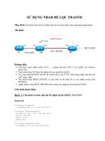
Figure 5: Creating a new IP Security Connection Rule.
1. In the Windows Firewall with Advanced Security window right-click on “Conection Security Rules”. This opens the menu as shown in Figure 5(left). Click “New
Rule...” to open the “New Connection Security Rule Wizard” (Figure 5(right)).
2. In the “Rule Type” window select “Custom Rule” and then click on “Next”.
Figure 6: (left) Specifying computers between which secure connections will be established using IPSec. (right) Specifying the authentication requirements for connections.
3. This leads us to “Endpoints” window where you specify computer endpoints between which a secure connections using IPSec will be established (Figure 6(left)).
For Endpoint 1 select “These IP addresses” and click on “Add...” to enter IP
address of the first endpoint. Set this to the IP address of your local computer
(e.g., 10.0.1.58) and click “OK”. Similarly for Endpoint 2 specify the destination address of the IP traffic. Set this to the IP address of your partner computer
(e.g., 10.0.1.59). Click “Next” to forward to “Requirements” window.
FESB
Computer and Network Security Course
5
4. In the “Requirements” window you specify the authentication requirements for
connections (Figure 6(right)). Select “Require authentication for inbound and
outbound connection”.
Figure 7: Specifying how authentication is performed for connections.
5. Click “Next” then in the “Authentication Method” window select “Advanced”
and click “Customize” (Figure 7(left)). After that in “Customize Advanced Authentication Methods” window in “First authentication methods” window on
the left side click “Add” to use the “preshared key”- based authentication (Figure 7(right)). Agree on a secret key with your partner and write the secret in the
appropriate field. Click “OK” and return to “Authentication Method” window.
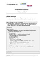
Figure 8: (left) Specifying protocols and ports to which our IPSec rule specifies to.
(right) A new IP Security Rule created and activated.
6. Next in “Protocols and Ports” window we specify protocols and ports to which
our IPSec rule specifies to. Select “ICMPv4” as a protocol type (Figure 8(left)).
FESB
Computer and Network Security Course
6
7. Click “Next” and then apply the rule to all profiles (Domain, Private and Public).
Click “Next” and enter the name of the created IPSec policy. Name it, for
example, as “FESB IPSec Transport”. Click “Finish”. A new IP security rule
has been created and configured (see Figure 8(right)).
Figure 9: Specifying settings used by IPSec to establish secure connections.
8. On the console tree to the left right click the “Windows Firewall with Advanced
Security” and select “Properties” (Figure 9(left)). From the “IPSec Settings”
tab click the “Customize” button for “IPsec defaults”, then set the “Data protection (Quick Mode)” to “Advanced” and click “Customize” (Figure 9(left)).
Here you can specify whether to use the AH or ESP protocol, what integrity
and/or encryption algorithms to use, and some settings related to a session key
(Figure 9(right)). We will start our study of IPSec with the AH protocol in the
transport mode. Specify the settings for a custom security method accordingly.
Please note that you have to coordinate your activities (use the same settings)
with your partner. Click “OK” in the “Customize Data Protection Settings” window (Figure 9(right)), after that in the “Customize IPsec Setting” window and
finally in the “Windows Firewall with Advanced Security Properties” window to
finalize IPSec configuration.
Before testing the new security policy, we need to create a rule for the ICMPv4 Inbound
and Outbound traffic. To accomplish this perform the following steps:
1. On the console tree to the left in “Windows Firewall with Advanced Security”
window right click on the “Inbound Rules” and click “New Rule”. In the “New
Inbound Rule Wizard” window select “Custom” (Figure 10(left)).
2. Click “Next” to open “Program” window. Leave by default the rule that applies to “All programs” on the computer that matches the rule properties (Figure 10(right)).
FESB
Computer and Network Security Course
7
Figure 10: (left) New Inbound Rule Wizard. (right) Matching the rule to all connections on the computer.
Figure 11: (left) Specifying protocols and ports our Inbound rule applies to. (right) A
new IP Security Rule created and activated.
3. Click “Next” to open “Protocols and Ports” window. Select “ICMPv4” as a
protocol type (Figure 11(left)).
4. Click “Next” to open “Scope” of local and remote IP addresses this rule applies
to. In the local IP addresses dialog select “These IP addresses” and Click on
“Add” where you enter your local IP address (Figure 11(right)). Similarly, in the
remote IP address dialog select “These IP addresses” and click on “Add” where
you will enter the IP address of your partner computer.
5. Click “Next” and select “Allow the connection” in the “Action” window (Figure 12).
FESB
Computer and Network Security Course
8
Figure 12: Specifying the action to be taken when a connection matches the conditions
specified in the rule.
6. Click “Next” and in the “Profile” window select that the rule applies to all profiles
(Domain, Private and Public).
7. Click “Next” to open “Name” window. Enter the name of the created policy for
the Inbound rule. Name it, for example, as “ICMPv4 Inbound”. Click “Finish”.
A new Inbound rule has been created and configured.
8. In a similar way create a rule for the ICMPv4 Outbound traffic. To accomplish
this on the console tree to the left right click on the “Outbound Rules”, then
click “New Rule”, and repeat the above steps (1-7).
Finally, activate the new security policy (e.g., “FESB IPSec Transport”) on a local computer. To accomplish this, in the Windows Firewall with Advanced Security window
right-click on the new security policy and select “Enable Rule” (see Figure 8(right)).
The value of the “Enabled” column should change from “No” to “Yes”. Please note
that your partner should activate the corresponding security policy on his/her computer too.
NOTE: If a mistake has been made during the configuration process you are
not required to go through the whole process anew. You can simply edit
any existing IPSec rule using the editor that pops-up when you double-click
on that rule.
Task 1.2. Testing the IPSec Transport Mode Configuration
1. Check out the “Main Mode” and “Quick Mode” sections under the Security
Associations and you should see connections from your local IP under the Local
Address going to the partner IP under Remote Address (Figure 13).
FESB
Computer and Network Security Course
9
Figure 13: Testing the connections from your local IP address to the partner IP address.
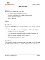
2. You can verify the correctness of your IPSec configuration by pinging the partner computer. While pinging the partner computer observe network traffic using
Wireshark. At the stage where two computers did not establish any security association (SA) with each other, before you observe any ICMP packets (due to ping
utility) you should first observe ISAKMP packets as shown in Figure 14. Answer
Figure 14: ISAKMP packets captured by Wireshark.
what do the two sets of ISAKMP messages (six and four ISAKMP messages)
represent?
3. You may not be able to see ISAKMP messages if the two computers have al-
FESB
Computer and Network Security Course
10
ready established security associations (SA) with each other. To enable this
you should remove any existing security associations from the local computer.
This can be accomplished by restarting the IPSec Policy Agent. Open the Windows command mode and type first net stop policyagent then net start
policyagent. Now, when you ping a partner computer for the first time, you
should observe the same set of ISAKMP messages as the ones in Figure 14.
4. Using Wireshark try to extract the AH header from ICMP packets. Change
the IP Sec policy to use the ESP protocol in the transport mode. Again, try
to extract the ESP header and other relevant fields due to the ESP protocol.
Contrast AH protected ICMP packets with ESP protected ones.
Task 1.2. Answer the Following Questions
• Examine the content of the very first ISAKMP packet exchanged between two
computer that do not share yet any security association. Explain the content of
the two fields Initiator cookie and Responder cookie.
• Observe the cookies from the 2nd ISAKMP message. Explain your observation.
• If the AH protocol is used in the transport mode, can you read the content of
the protected IP packets? How about the ESP protocol? Explain your answer.
• Extract the AH header from a IPSec protected IP packet. Explain the role of
each of the fileds from the AH header.
Exercise 2
In this exercise we will study the IPSec tunnel mode of operation. The tunnel mode is
generally used to protect communication between two security gateways. Its operation
is illustrated Figure 15. Thus, in the tunnel mode an IP packet to be protected is
considered to be a payload of another IPSec protected IP packet. Consequently a new
IP header, in addition to an IPSec header, is appended to the original IP packet. In
New
novo IP
IP header
zaglavlje
IPSec
IPSec
IP
IP header
zaglavlje
Packet
ostatakpayload
paketa
IP
IP header
zaglavlje
Packet
ostatakpayload
paketa
Figure 15: The transport mode of operation in IPSec.
the tunnel mode, the ESP protocol encrypts and optionally authenticates the whole
FESB
Computer and Network Security Course
11
IP packet (Figure 16), whereas the AH protocol authenticates the whole original IP
packet and selected fields from the IP header of the new packet (Figure 16).
original IP packet
original
TCP/UDP
original
TCP/UDP
IP
IP header
header header
header
data
data
ESP in tunnel mode
new
ESP
original
TCP/UDP
new
ESP
original
TCP/UDP
IP
IP header
header header
header IP
IP header
header header
header
ESP
ESP
trailer
trailer
data
data
ESP
MAC
MAC
encrypted
authenticated
AH in tunnel mode
new
new
IP
IP header
header
AH
AH
original
TCP/UDP
original
TCP/UDP
IP
IP header
header header
header
data
data
authenticated except for mutable fields in the outer IP header (e.g., TTL)
Figure 16: ESP and AH in the tunnel mode of operation.
Task 2.1. Configuring the IPSec Tunnel Mode
In order to configure the IPSec tunnel mode, we will follow essentially the same steps
as in the case of the transport mode. Therefore, in the instructions below we will
emphasize only those steps that are fundamentally different from the steps followed
during the configuration of the transport mode.
1. In the “Rule Type” window select “Tunnel” and then click “Next”.
2. In the “Tunnel Type” window select “Custom configuration” as the tunnel type,
and select “No. Send all network traffic that matches this connection security rule
through the tunnel” since we do not want to exempt IPSec protected connections
from the tunnel.
3. In the “Tunnel Endpoints” window as an Endpoint 1 add your local IP address.
Also, as the local tunnel endpoint enter your local IP address. On the other
side, as an Endpoint 2 and a remote tunnel endpoint enter the IP address of the
partner computer.
4. At the end enter the Name of the created IPSec policy. Name it, for example, as
“FESB IPSec Tunnel”. Click “Finish”.
5. To activate the new policy (e.g., in our example “FESB IPSec Tunnel”), rightclick on it and select “Enable”.
FESB
Computer and Network Security Course
12
NOTE: If a mistake has been made during the configuration process you are
not required to go through the whole process anew. You can simply edit
any existing IPSec rule using the editor that pops-up when you double-click
on that rule.
Task 2.1. Testing the IPSec Tunnel Mode Configuration
1. Again, you can verify the correctness of your IPSec configuration by pinging the
partner computer. While pinging the partner computer observe network traffic
using Wireshark. At the stage where two computers did not establish any security
association (SA) with each other, before you observe any ICMP packets (due to
ping utility) you should first observe ISAKMP packets as shown in Figure 14.
2. Provide evidence that your computer actually operates in the tunnel mode. (Hint:
Use Wireshark.)
3. Test both the AH and ESP protocol in the tunnel mode.
4. Use the “Event Viewer” from the MMC console (see Figure 17) and analyze one
event (of type “Audit Success”) that corresponds to a successful execution of the
IKE protocol. To see details of a given event, simply double-click on it. To install
Event Viewer service repeat the following steps:
(a) Click “Start . Run” and type “mmc”. This opens the “Microsoft Management Console”.
(b) Click “File . Add/Remove Snap-in”.
(c) In the resulting window click “Add”.
(d) Add the “Computer Management” snap-in.
Figure 17: Event Viewer in Microsoft Management Console (MMC).
THE END