color atlas of temporomandibular joint surgery - p. quinn
Bạn đang xem bản rút gọn của tài liệu. Xem và tải ngay bản đầy đủ của tài liệu tại đây (20.96 MB, 248 trang )
CONTENTS
1 Surgical Decision Making for Temporomandibular
Joint Surgery, 1
2 Diagnostic Imaging of the Temporomandibular Joint, 4
3 Surgical Approaches to the Temporomandibular Joint, 30
4 Surgery for Internal Derangements, 55
5 Osseous Surgery of the Temporomandibular Joint, 100
6 Trauma, 125
7 Autogenous and Alloplastic Reconstruction of the
Temporomandibular Joint, 170
8 Pathology of the Temporomandibular Joint, 213
SURGICAL DECISION
MAKING IN
TEMPOROMANDIBULAR
SURGERY
CHAPTE R ON E
" Who shall decide when doctors disagree?
ALEXANDER POPE IN "OF THE USE or RICHES"
»
learly, one of the most vexing problems for oral and maxillofacial surgeons has
been selecting the proper surgical option for those patients who have
exhausted all conservative methods of dealing with temporomandibular joint pain
and dysfunction. Well-reasoned controversy can complicate decision making in
temporomandibular joint surgery for internal derangement, trauma, and manage-
ment of benign and malignant disorders. Several excellent comprehensive text-
books on temporomandibular joint disorders explore the basis for these contro-
versies and provide a historical and scientific overview of this problematic area of
maxillofacial surgery.
The intent of this text is simply to illustrate the technical aspects of the vari-
ous surgical procedures on the temporomandibular joint. No attempt was made to
champion a single approach to temporomandibular joint surgery. Ultimately, only
well-designed clinical studies can prove or disprove the safety and efficacy of the
individual procedures. It is our hope scientific evidence will one day provide the
sine qua non that will dictate the proper role for all the potential surgical modali-
ties, including arthroscopy, meniscal repair, and the use of both autogenous and
alloplastic materials in joint reconstruction. Although serious mistakes have been
made in the management of the temporomandibular joint, surgeons cannot allow
the sins of the past to obscure the needs of the future.
This text is based on the assumption that primarily extraarticular conditions
are most amenable to nonsurgical care. Patients with true internal derangements
may benefit from nonsurgical care, and all these modalities should be exhausted
before proceeding with any surgical option. The following algorithms are useful as
guidelines but must always be modified according to the needs of the individual
patient. Because several excellent comprehensive texts dealing with arthroscopic
techniques are available, this book deals only with open joint surgical procedures.
1
2
Color Atlas of Temporomandibular joint Surgery
Chapter One Surgical Decision Making in Temporomandibular Surgery
3
CHAPTE R
TWO
DIAGNOSTIC
IMAGING
OF
THE TEMPOROMANDIBULAR
JOINT
B
ecause of the anatomic complexity of the temporomandibular joint and its
proximity to the temporal bone, mastoid air cells, and auditory structures,
imaging of the joint structures can be problematic.
PLAIN FILM, TOMOGRAMS , AND PANORAMI C
RADIOGRAPH Y
Initial screening for gross osseous abnormalities can be performed with standard
transcranial (lateral oblique) views. The x-ray beam is angled superiorly to project
the joint away from the base of the skull. The transcranial perspective provides a
global view of gross bony architecture of the articular surfaces. If possible, a sub-
mental vertex film can be taken to allow the lateral oblique transcranial projection
to be angled directly through the long access of the condyle. This improves the
image quality and also allows standardization of subsequent transcranial views.
Tomography has been widely available since the early 1940s and provides finer
detail for the examination of osseous abnormalities than that detected by plain
film techniques. The angle-corrected tomograms for sagittal tomography are rec-
ommended so that the sectioning is always perpendicular to the long axis of the
condyle. This gives a truer picture of the condylar position and allows subsequent
comparative studies to be performed by use of a standard method. The angle can
be determined by measuring the angle between the condylar axis and a horizontal
baseline on a submental vertex view.
Panoramic radiographs have been described as "curved tomograms." They
are, in fact, laminograms of a single plane that are adequate for gross screening
but limited because of inherent problems with distortion, "ghost" images, magni-
fication (approximately 20%), and a loss of sharpness compared with multiple-
cut, angle-corrected, condylar tomograms.
Newer units allow for separate positioning of right and left joints, creating
more correct placement of the condyle in the zone of focus.
Plain films and tomographic images are a great benefit in assessing osseous
changes in the condyle and eminence. However, the use of these films to assess
condylar position with any accuracy is questionable at best. Several studies have
shown that the position of the condyle, as depicted in these radiographic tech-
niques, is of little clinical significance. Open- and closed-mouth tomographic views
can provide valuable information with regard to condylar translation. Although
4
conventional textbooks have claimed that during normal range of motion the
greatest convexity of the condyle reaches the greatest convexity of the articular
eminence, several studies have shown that a majority of patients actually can trans-
late beyond the greatest convexity of the articular eminence without subluxation,
dislocation, or any symptoms. These studies can diagnose restricted range of
motion bur do not provide enough information to determine the etiology of that
restriction.
Text continued on p. II
A
5
Chapter Two Diagnostic Imaging of the Temporomandibular joint
Chapter Two
B
FIG. 2.1
Transcranial radiograph to image contralateral temporomandibular joint. A, Correct positioning.
B, Radiographic image.
Color Atlas of Temporomandibular Joint Surgery
A
C
Regular tomography
Correcte d tomography
A, Positioning for submental vertex film to determine angulation of condylar head for angle-corrected
tomograms. B, Submental vertex view of skull with measurements for angle-corrected tomogram tech-
nique. C, Example of 35-degree correction to ensure that tomograms are perpendicular to line drawn
from the medial to lateral pole of the condyle.
6
B
FIG. 2.2
Chapter Two Diagnostic Imaging of the Temporomandibular joint
Representation of sagittal cuts in standard tomographic condylar films, showing representative anatomy
7
gram of right temporomandibular joint.
A
B
FIG. 2.3
FIG. 2.4
from the most lateral to the most medial cut.
A, Patient positioned for angle-corrected temporomandibular joint tomograms. B, Angl&corrected tomo-
Color Alias of Temporomandibular Join! Surgery
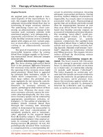
Severe
Tomographic technique —Basic principle of tomographic x-rays. Both Expected contours of lateral condylar tomograms in varying stages
the radiation source and film are moving simultaneously to blur all of degenerative joint disease,
the anatomy anterior and posterior to the point of plane conver-
gence.
8
FIGS. 2.5, 2.6
Chapter Two Diagnostic Imaging of the Temporomandibular joint
Degenerative condylar changes. A, Stage I. B, Stage II "birds beaking"
9
Temporomandibular joint-tomographic series depicting excellent osseous detail with 5 mm cuts.
A
B
FIG. 2.7
FIG. 2.8
10
Color Athis of Temporomandibular Joint Surgery
A, Patient positioned for panoramic tomogram of the temporomandibular joints. B, Example of pro-
grammed condylar views available on most panoramic tomographic units. C, Bilateral positioning tech-
niques for specific temporomandibular joint-panoramic x-ray imaging positioned to align the condyle into
the center of the "trough" of resolution of the panoramic tomogram.
A
B
c
FIG. 2.9
Chapter Two Diagnostic Imaging of the Temporomandibular Joint
BONE SCANS
Radionuclide imaging of the temporomandibular joint can provide information
about the dynamics of bone metabolism in a variety of pathologic states. A scin-
tillation camera can be used for both dynamic and static imaging in which a
gamma detector quantifies gamma ray emissions from injected isotopes such as
technetium 99. These technetium-labcled phosphate complexes are given to
patients by intravenous injection, and then the patients are studied in a phased
technique with images performed immediately after injection and at several
delayed intervals. The uptake of these radiopharmaceutical agents depends on
blood flow to the temporomandibular joint structures. The profusion of the tem-
poromandibular joint is affected by inflammation, bone remodeling, and
osteoblastic activity. Higher activity is seen at sites of growth, inflammation, and
neoplasia and areas where reactive bone is formed during reparative processes.
Because they arc rather nonspecific, radionuclide images can be difficult to inter-
pret without good clinical correlation. They are usually not indicated in evaluation
and treatment of osteoarthritis and disk displacements. Radionuclide images can
be helpful in cases such as occult osteomyelitis and condylar hyperplasia.
11
FIG. 2.10
"Hoof" deformit y in condyla r head, secondary to condyla r trauma during growth.
12
Color Atlas of Temporomandibular Joint Surgery
Technetium 99 bone scan. A, B, Total body bone scan. C, Positive bone scan with enhancement of
right temporomandibular joint, secondary to condylar hyperplasia. D, Nonspecific positive bone scan of
left temporomandibular joint, secondary to psoriatic arthritis.
A
B
c
D
FIG. 2.11
Chapter Two Diagnostic Imaging of the Temporomandibular Joint
13
ARTHROGRAPH Y
Although arthrography is not widely used, it can offer valuable information nor
always available through any other imaging technique. The usual technique
involves injection of a water-soluble, iodinated contrast material into the inferior
joint space under fluoroscopy. A videotaped arthrofluoroscopic study could
clearly show the various stages of disk displacement with or without reduction. It
is the only imaging technique that demonstrates perforations in the disk in "real-
time" because the operator can see the dye escape from the inferior to the supe-
rior joint space during the initial injection. The majority of temporomandibular
joint arthrograms are performed with single space injection (inferior joint space),
although double space arthrograms can also be performed. Basically, for single
space arthroscopy, the auricular temporal nerve is anesthetized, and a small
amount of local anesthetic is injected into the region of the joint puncture. Under
fluoroscopic guidance, a 23-gauge needle is directed into the posterior inferior
joint space. When the tip of the needle encounters the condyle, 0.2 to 0.4 ml of
contrast material is injected into the posterior recess of the inferior joint space.
Alter confirming that the contrast is in the proper space, the clinician instructs the
patient to open and close the mouth, and dynamic videotape images are recorded
during opening and closing. The pattern of dye deformation within the inferior
joint space is the basis for diagnosing internal derangements.
A, The normal condyle-dis k relationshi p in the closed position . Mote that the junction of the posterio r
attachment and the posterio r band correlate s to the condylar head at the 12 o'clock position.
B, Arthrogra m — Note 23-gaug e needle entering the inferior joint space from a posterio r inferior
approach. This is performe d under fluoroscop y to ensure that the dye is being injected into the inferior
joint space and to note any immediat e egress of the dye into the superio r joint space, which would be
consistent with menisca l perforation . Continued
A
B
Text continued on p. 18
FIG. 2.12
14
Color Atlas of Temporomandibular joint Surgery
Normal Temporomandibular Joint
C, Arthrography findings in a normal temporomandibular joint articulation in the closed and open posi-
tions. Note that almost all the dye in the anterior recess of the inferior joint space is forced into the poste-
rior -ecess at the terminal opening position. D, Diagrammatic representation of changes in inferior and
superior joint spaces during condylar translation. E, Placement of 23-gauge needle into posterior recess of
inferior joint space for placement of approximately 0.5 ml of iodinated contrast material.
c
E
D
FIG. 2.12, CONT'D
Chapter Two Diagnostic Imaging of the Temporomandibular Joint
15
the superior boundary of the inferior joint space, as depicted in the single space arthrogram. B, Normal
configuration of the inferior joint space in single space arthrography in the closed position C, Open and
closed mouth views of normal, asymptomatic, healthy volunteer patient depicting expected deformation of
inferior joint space during open and closed maneuvers. D, Same patient as in C with double contrast
technique (injection of dye into both inferior and superior joint spaces).
B
A, Inferior joint arthrography depicting anterior meniscal displacement with secondary deformity in the
anterior recess of the inferior joint space. B, Arthrographic findings in A.
A
B
A
FIG. 2.13
FIGFIG. 2.14
A, Sagittal section depicting normal condyle disk relationship. The inferior border of the meniscus outlines
16
Color Atlas of Temporomandibular Joint Surgery
Anterior dislocation of meniscus secondary to stretching an elongation of the posterior attachment. Note
that the junction of the posterior attachment and the meniscus approximately at the 3 o'clock position with
regard to the condylar surface.
Representation of reciprocal clicking, secondary to anterior displace-
ment with reduction.
The closed-lock position, secondary to anterior displacement without
reduction.
FIG. 2.15
FIGS. 2.16, 2.17
Chapter Two Diagnostic Imaging of the Temporomandibular Joint
17
A, Sagittal section showing normal condyle disk position with junction of posterior attachment and poste-
B, Diagrammatic representation.
Abnormal arthrogram in a patient with anterior dislocation with reduction. The abnormality is apparent in
the closed position because the dye in the anterior recess is being pushed into a more inferior position by
the displaced disk. On terminal opening, after reduction, the dye repositions into the posterior recess of
the inferior joint space.
A
B
Open
FIG. 2. 18
rior band of disk aligned approximately at the 12 o'clock position with regard to the condylar surface.
FIG. 2.19
Closed
Color Atlas of Temporomandibular joint Surgery
Anletior dislocation without reduction (closed-lock) — arthrographic findings in a patient with a closed posi-
tion. Even when the patient is in the position of maximol interincisal opening, the expected displacement
Potential complications from arthrography include allergic reaction to the con-
trast material, infection, and pain and swelling secondary to the mechanical instru-
ments used during the procedure.
Magnetic resonance imaging has replaced arthrography in most instances for
soft tissue imaging of the temporomandibular joint.
Disadvantages of Arthrography
• Invasiveness
• Pain (intraoperative or postoperative)
• Risk of infection
• Potential damage to disk, capsule, and fibrocartilage
• Allergy to contrast material (or local anesthetic)
COMPUTERIZED TOMOGRAPHY
Computerized tomography (CT) of the temporomandibular joints is currently the
best method for assessing bony pathologic conditions. It is difficult to position a
patient within the gantry for true direct sagittal cuts, and reconstructed sagittal
views can be less than ideal.
Axial and coronal views are excellent for assessing normal and abnormal
osseous anatomy. CT images arc rarely used as the primary mode of diagnosing disk
displacement. In most instances, accurate differentiation between meniscal tissue
and portions of the lateral pterygoid muscle is difficult on CT. Disk displacement is
frequently inferred from the degenerative changes seen on CT scanning, such as flat-
tening of the anterior superior slope of the condyle, increased sclerosis, gross remod-
eling of the condylar head and articular eminence, and osteophyte formation.
Three-dimensional CT images can be helpful in cases of gross asymmetry for
planning orthognathic surgery or joint reconstruction.
Closed
Open
18
of the dye into the posterior recess does not occur.
FIG. 2.20
Chapter Two Diagnostic Imaging of the Temporomandibular joint
19
A, Seoul film for direct sagittal CTs. Note thai even with ihese maneuvers, it is difficult to position the
palient for a true sagittal view of the craniomandibular articulation. B, Direct sagittal bone window view
of the temporomandibular joint. Note the detail and clarity of the osseous structure.C, Positioning of a
patient for a direct sagittal CT scan of the temporomandibular joints. Note that a separate gurney must be
used to bring the patient in at an angle to the CT gantry. The patient in this representation must also
extend the left arm through the gantry to bring the joint into the proper plane for imaging D, Patient posi-
tioning for direct sagittal CT of temporomandibular joints.
A
B
c
D
FIG. 2.21
Direct sagittal CT scans of the
right temporomandibular joint
with a bone window (A and B)
and the same patient image with
a soft tissue window (C and D).
Note the difficulty in ascertairing
the exact position of the meniscus
in the soft tissue windows. This is
clearly the reason that CT scan-
ning remains the gold standard in
the diagnosis of osseous patho-
logic conditions within the joint
but is not widely used for diagno-
sis of internal derangement.
A, Computer tomogram of the temporomandibular joint in coronal plane depicting marked sclerosis of the
temporomandibular joint with evidence of fibroosseous ankylosis of the joint. B, Axial computer tomogram
of the same patient, depicting that sclerosis also affects the base of the skull.
B
A
c
D
A
B
FIG. 2.22
FIG. 2.23
A, Autopsy specimen of mandibular condyle in anterior posterior
view showing dimensions from medial to lateral pole, which can
average between 17 and 23 mm. B, Coronal CT scan through
midpoint of condyle, showing normal condylar structure and joint
space dimension.
A, Three-dimensional CT scan reconstructed with axial and coro-
nal cuts. Note that there is no edging at the boundaries of the
individual CT cuts because the software interprets the imaging
gaps based on standard algorithms. B, C, Computer manipu-
lation of three-dimensional CT scan that allows selected and spe-
cific views of osseous anatomy. Note the small defect on the pos-
terior surface of the neck of the condyle in B. It depicts a defect
created with '/2-mm round bur in an autopsy specimen to illus-
trate the sensitivity of this imaging technique.
A
B
A
B
c
FIG. 2.24
FIG. 2.25
22 Color Alias of Temporomandibular Joint Surgery
MAGNETIC RESONANCE IMAGING
Magnetic resonance (MR) images can be obtained in the sagittal, axial, and coronal
planes. Slice thickness usually varies between 3 and 10 mm. Thinner sections result
in improved image quality because "volume averaging" of the structures is reduced.
In most normal scanning sequences, both Tl weighted and T2 weighted images will
be obtained. With the most commonly used pulsed sequence (spin-echo), Tl
weighted images highlight fat within the tissues and T2 weighted images may give a
poorer image quality but highlight water-containing structures. These T2 weighted
images are particularly helpful when the operator is attempting to determine
whether a joint effusion exists. The major contraindication to magnetic resonance
imaging (MRI) is posed by ferromagnetic metals. Ferromagnetic clips used to treat
Proper head positioning for dual surface coil MR study of the temporomandibular joints.
FIG. 2.26
Chapter Two Diagnostic Imaging of the Temporomandibular Joint
a cerebral aneurysm are an absolute contraindication to MR scanning. The other
absolute contraindication occurs with patients who have cardiac pacemakers.
Nonfcrromagnetic metals, such as those used in orthodontic braces and Vitallium
prostheses, do not pose problems related to magnetic fields but do compromise
image quality because of artifact production. Although MRI is clearly preferred for
assessing internal derangements, all patients with joint symptoms do not require MR
studies. Transcranial radiographs or condyle-specific panoramic films are certainly
adequate to assess whether a patient has gross degenerative changes within the joint.
If a reasonable attempt at conservative therapy does not improve symptoms and fur-
ther documentation of the internal derangement is necessary to determine whether
the patient may be a surgical candidate, then MRI should be considered.
A, B, Coronal MR images of temporomandibular joint in asymptomatic individual.
23
A
B
FIG. 2.27