electrochemical methods. fundamentals and applications
Bạn đang xem bản rút gọn của tài liệu. Xem và tải ngay bản đầy đủ của tài liệu tại đây (23.21 MB, 850 trang )
SECOND EDITION
ELECTROCHEMICAL
METHODS
Fundamentals
and
Applications
Allen
J.
Bard
Larry
R.
Faulkner
Department
of
Chemistry and Biochemistry
University
of
Texas at Austin
JOHN WILEY
&
SONS, INC.
New
York
e
Chichester
•
Weinheim
Brisbane
e
Singapore
e
Toronto
Acquisitions Editor David Harris
Senior Production Editor Elizabeth Swain
Senior Marketing Manager Charity Robey
Illustration Editor Eugene Aiello
This book was set in 10/12 Times Roman by University Graphics and printed and bound by
Hamilton. The cover was printed by Phoenix.
This book is printed on acid-free paper, oo
Copyright 2001
©
John Wiley
&
Sons,
Inc. All
rights reserved.
No part
of
this publication
may be
reproduced, stored
in a
retrieval system
or
transmitted
in any
form
or by any
means, electronic, mechanical, photocopying, recording, scanning
or
otherwise, except
as
permitted under
Sections
107 or 108 of the
1976 United States Copyright Act, without either
the
prior written permission
of the
Publisher,
or
authorization through payment
of
the appropriate per-copy
fee to the
Copyright Clearance Center,
222 Rosewood Drive, Danvers,
MA
01923,
(978)
750-8400,
fax
(978) 750-4470. Requests
to the
Publisher
for
permission should
be
addressed
to the
Permissions Department, John Wiley
&
Sons, Inc.,
605
Third Avenue,
New York,
NY
10158-0012,
(212)
850-6011,
fax (212)
850-6008, E-Mail:
To order books
or for
customer service, call
1
(800)-CALL-WILEY (225-5945).
Library
of
Congress Cataloging
in
Publication Data:
Bard, Allen
J.
Electrochemical methods
:
fundamentals
and
applications
/
Allen
J.
Bard, Larry
R.
Faulkner.—
2nd ed.
p.
cm.
Includes index.
ISBN 0-471-04372-9 (cloth
: alk.
paper)
1.
Electrochemistry.
I.
Faulkner, Larry
R., 1944- II.
Title.
QD553.B37 2000
541.3'7_dc21
00-038210
Printed
in the
United States
of
America
10 987654321
PREFACE
In
the twenty years since the appearance of our
first
edition, the
fields
of electrochemistry
and
electroanalytical chemistry have
evolved
substantially. An improved understanding
of phenomena, the further development of experimental tools already known in 1980, and
the
introduction of new methods have all been important to that evolution. In the preface
to
the 1980 edition, we indicated that the focus of electrochemical research seemed
likely
to
shift from the development of methods toward their application in studies of chemical
behavior. By and large, history has
justified
that
view.
There have also been important
changes in practice, and our 1980
survey
of methodology has become dated. In this new
edition,
we have sought to update the book in a way that
will
extend its value as a general
introduction
to electrochemical methods.
We have maintained the philosophy and approach of the original edition, which is to
provide comprehensive coverage of fundamentals for electrochemical methods now in
widespread use. This volume is intended as a textbook and includes numerous problems
and
chemical examples. Illustrations have been employed to clarify presentations, and the
style
is pedagogical throughout. The book can be used in formal courses at the senior un-
dergraduate and beginning graduate
levels,
but we have also tried to write in a way that
enables
self-study
by interested individuals. A knowledge of basic physical chemistry is
assumed, but the discussions generally begin at an elementary
level
and develop upward.
We have sought to make the volume self-contained by developing almost all ideas of any
importance
to our subject from
very
basic principles of chemistry and physics. Because
we
stress
foundations and limits of application, the book continues to emphasize the
mathematical
theory underlying methodology; however the key ideas are discussed con-
sistently apart from the mathematical
basis.
Specialized mathematical background is cov-
ered as needed. The problems
following
each chapter have been
devised
as teaching tools.
They often extend concepts introduced in the text or show how experimental data are re-
duced to fundamental results. The cited literature is extensive, but mainly includes only
seminal papers and
reviews.
It is impossible to cover the huge body of primary literature
in
this
field,
so we have made no attempt in that direction.
Our
approach is
first
to
give
an
overview
of electrode processes (Chapter 1), show-
ing the way in which the fundamental components of the subject come together in an
electrochemical experiment. Then there are individual discussions of thermodynamics
and
potential, electron-transfer kinetics, and mass transfer (Chapters 2-4). Concepts
from these basic areas are integrated together in treatments of the various methods
(Chapters
5-11). The effects of homogeneous kinetics are treated separately in a way
that
provides a comparative
view
of the responses of different methods (Chapter 12).
Next
are discussions of interfacial structure, adsorption, and modified electrodes
(Chap-
ters 13 and 14);
then
there is a taste of electrochemical instrumentation (Chapter 15),
which is followed by an extensive introduction to experiments in which electrochemistry
is coupled with other tools (Chapters 16-18). Appendix A teaches the mathematical
background; Appendix В provides an introduction to digital simulation; and Appendix С
contains
tables of useful data.
vi • Preface
This structure is generally that of the 1980 edition, but important additions have been
made
to cover new topics or subjects that have
evolved
extensively.
Among them are ap-
plications of ultramicroelectrodes, phenomena at well-defined surfaces, modified elec-
trodes,
modern electron-transfer theory, scanning probe methods, LCEC, impedance
spectrometry, modern forms of pulse voltammetry, and various aspects of spectroelectro-
chemistry. Chapter 5 in the
first
edition ("Controlled Potential Microelectrode Tech-
niques—Potential
Step Methods") has been divided into the new Chapter 5
("Basic
Potential
Step Methods") and the new Chapter 7 ("Polarography and Pulse Voltamme-
try").
Chapter 12 in the original edition ("Double Layer Structure and Adsorbed Interme-
diates in Electrode Processes") has become two chapters in the new edition: Chapter 12
("Double-Layer Structure and Adsorption") and Chapter 13 ("Electroactive Layers and
Modified Electrodes"). Whereas the original edition covered in a
single
chapter experi-
ments
in which other characterization methods are coupled to electrochemical
systems
(Chapter
14, "Spectrometric and Photochemical Experiments"), this edition features a
wholly new chapter on "Scanning Probe Techniques" (Chapter 16), plus separate chapters
on
"Spectroelectrochemistry and Other Coupled Characterization Methods" (Chapter 17)
and
"Photoelectrochemistry and Electrogenerated Chemiluminescence" (Chapter 18). The
remaining chapters and appendices of the new edition directly correspond with counter-
parts in the old, although in most there are quite significant revisions.
The
mathematical notation is uniform throughout the book and there is minimal du-
plication of symbols. The List of Major Symbols and the List of Abbreviations offer defi-
nitions,
units, and section references. Usually we have adhered to the recommendations of
the
IUPAC Commission on Electrochemistry [R. Parsons et al.,
Pure
Appl.
С hem., 37,
503 (1974)]. Exceptions have been made where customary
usage
or clarity of notation
seemed compelling.
Of necessity, compromises have been made between depth, breadth of coverage, and
reasonable size. "Classical" topics in electrochemistry, including many aspects of thermo-
dynamics of cells, conductance, and potentiometry are not covered here. Similarly, we
have not been able to accommodate discussions of many techniques that are useful but not
widely
practiced. The details of laboratory procedures, such as the design of cells, the
construction
of electrodes, and the purification of materials, are beyond our scope. In this
edition,
we have deleted some topics and have shortened the treatment of others. Often,
we have achieved these changes by making reference to the corresponding
passages
in the
first
edition,
so that interested readers can
still
gain access to a deleted or attenuated topic.
As with the
first
edition, we owe thanks to many others who have helped with this
project. We are especially grateful to Rose McCord and Susan Faulkner for their consci-
entious
assistance with myriad details of preparation and production.
Valuable
comments
have been provided by S. Amemiya, F. C. Anson, D. A. Buttry, R. M. Crooks, P. He,
W. R. Heineman, R. A. Marcus, A. C. Michael, R. W. Murray, A. J. Nozik, R. A. Oster-
young, J M. Saveant, W. Schmickler, M. P. Soriaga, M. J.
Weaver,
H. S. White, R. M.
Wightman, and C. G. Zoski. We thank them and our many other colleagues throughout
the
electrochemical community, who have taught us patiently over the years. Yet again,
we also thank our families for affording us the time and freedom required to undertake
such a
large
project.
Allen
/.
Bard
Larry R. Faulkner
CONTENTS
MAJOR
SYMBOLS
ix
STANDARD ABBREVIATIONS xix
1
INTRODUCTION AND
OVERVIEW
OF ELECTRODE PROCESSES 1
2 POTENTIALS AND THERMODYNAMICS OF CELLS 44
3 KINETICS OF ELECTRODE REACTIONS 87
4
MASS
TRANSFER BY MIGRATION AND DIFFUSION 137
5 BASIC POTENTIAL STEP METHODS 156
6 POTENTIAL SWEEP METHODS 226
7 POLAROGRAPHY AND PULSE VOLTAMMETRY 261
8 CONTROLLED-CURRENT TECHNIQUES 305
9 METHODS INVOLVING FORCED CONVECTION—HYDRODYNAMIC
METHODS
331
10 TECHNIQUES BASED ON CONCEPTS OF IMPEDANCE 368
11 BULK ELECTROLYSIS METHODS 417
12 ELECTRODE REACTIONS WITH COUPLED HOMOGENEOUS CHEMICAL
REACTIONS 471
13 DOUBLE-LAYER STRUCTURE AND ADSORPTION 534
14 ELECTROACTIVE
LAYERS
AND MODIFIED ELECTRODES 580
15 ELECTROCHEMICAL INSTRUMENTATION 632
16 SCANNING PROBE TECHNIQUES 659
17 SPECTROELECTROCHEMISTRY AND OTHER COUPLED CHARACTERIZATION
METHODS
680
18 PHOTOELECTROCHEMISTRY AND ELECTROGENERATED
CHEMILUMINESCENCE
736
APPENDICES
A MATHEMATICAL METHODS 769
В DIGITAL SIMULATIONS OF ELECTROCHEMICAL PROBLEMS 785
С
REFERENCE
TABLES
808
INDEX
814
MAJOR
SYMBOLS
Listed
below
are
symbols
used in
several
chapters or in
large
portions of a chapter. Sym-
bols similar to some of these may have different local meanings. In most cases, the
usage
follows
the recommendations of the IUPAC Commission on Electrochemistry [R. Par-
sons et al.,
Pure
Appl.
Chem.,
37, 503 (1974).]; however there are exceptions.
A bar over a concentration or a current [ej*., C
o
(x, s)] indicates the Laplace trans-
form of the variable. The exception is when / indicates an
average
current in polaro-
graphy.
STANDARD
SUBSCRIPTS
a
с
D
d
anodic
(a)
cathodic
(b) charging
disk
diffusion
dl
eq
f
/
double layer
equilibrium
(a)
forward
(b) faradaic
limiting
0
P
R
r
pertaining
to
species
0 in О + ne
±±
R
peak
(a)
pertaining
to
species
R in О + ne ^ R
(b) ring
reverse
ROMAN
SYMBOLS
Symbol Meaning
Usual
Units
Section
References
С
C
B
c
d
c't
(a)
area
(b) cross-sectional area
of a
porous
electrode
(c)
frequency factor
in a
rate expression
(d)
open-loop gain
of an
amplifier
absorbance
(a)
internal area
of a
porous electrode
(b)
tip
radius
in
SECM
activity
of
substance
j in a
phase
a
aFv/RT
capacitance
series equivalent capacitance
of a
cell
differential capacitance
of
the double
layer
integral capacitance
of
the double layer
concentration
of
species;
bulk concentration
of
species;
concentration
of
species;
at
distance
x
cm
cm
2
depends
on
order
none
none
cm
2
none
s"
1
mol/cm
2
F
F
F,
F/cm
2
F,
F/cm
2
M,
mol/cm
3
M,
mol/cm
3
M,
mol/cm
3
1.3.2
11.6.2
3.1.2
15.1.1
17.1.1
11.6.2
16.4.1
2.1.5
6.3.1
13.5.3
1.2.2,
10.1.2
10.4
1.2.2,
13.2.2
13.2.2
1.4.2, 4.4.3
1.4
Major Symbols
Symbol
CjCx
= 0)
Cj(x,
t)
Cj(O,
f)
Cj(y
= 0)
Csc
С
Dj(A,
E)
D
M
£s
d
*\
E
AE
E
%
%
E
£°
AE°
E°
E
0
'
E
A
E
ac
E
b
Edc
Meaning
concentration
of
species
j at the
electrode surface
concentration
of
species
у
at
distance
x
at
time
t
concentration
of
species у
at the
electrode surface
at
time
t
concentration
of
species у
at
distance
у
away
from rotating electrode
surface concentration
of
species у
at a
rotating electrode
space charge capacitance
pseudocapacity
speed
of
light
in
vacuo
diffusion coefficient
for
electrons within
the
film
at a
modified electrode
diffusion coefficient
of
species у
concentration
density
of
states
for
species у
model diffusion coefficient
in
simulation
diffusion coefficient
for the
primary
reactant
within
the
film
at a
modified
electrode
distance
of
the
tip
from
the
substrate
in
SECM
density
of
phase у
(a)
potential
of an
electrode
versus
a
reference
(b)
emf of a
reaction
(c)
amplitude
of an ac
voltage
(a)
pulse height
in
DPV
(b) step height
in
tast
or
staircase
voltammetry
(c)
amplitude
(1/2
p-p)
of ac
excitation
in
ac
voltammetry
electron
energy
electric
field
strength vector
electric
field
strength
voltage
or
potential phasor
(a)
standard potential
of an
electrode
or
a
couple
(b) standard
emf of a
half-reaction
difference
in
standard potentials
for
two couples
electron
energy corresponding
to the
standard potential
of a
couple
formal potential
of an
electrode
activation energy
of a
reaction
ac component
of
potential
base potential
in NPV and RPV
dc component
of
potential
Usual Units
M,
mol/cm
3
M,
mol/cm
3
M,
mol/cm
3
M,
mol/cm
3
M,
mol/cm
3
F/cm
F
cm/s
cm
/s
cm
2
/s
cm
3
eV~
!
none
cm
2
/s
/xm,
nm
g/cm
3
V
V
V
mV
mV
mV
eV
V/cm
V/cm
V
V
V
V
eV
V
kJ/mol
mV
V
V
Section
References
1.4.2
4.4
4.4.3
9.3.3
9.3.4
18.2.2
10.1.3
17.1.2
14.4.2
1.4.1,4.4
3.6.3
B.1.3.B.1.8
14.4.2
16.4.1
1.1,2.1
2.1
10.1.2
7.3.4
7.3.1
10.5.1
2.2.5,
3.6.3
2.2.1
2.2.1
10.1.2
2.1.4
2.1.4
6.6
3.6.3
2.1.6
3.1.2
10.1.1
7.3.2,
7.3.3
10.1.1
Symbol
Е
щ
E
F
Em
Eg
E;
Щ
E
m
E
P
A£
P
Ep/2
£pa
£pc
£
Z
*л
Еф
E\I2
Ещ
Е
Ъ1А
e
e\
e
0
ег%)
erfc(x)
F
f
/(E)
fUk)
G
AG
G
G°
Meaning
equilibrium
potential
of an
electrode
Fermi
level
flat-band
potential
bandgap
of a
semiconductor
initial
potential
junction
potential
membrane
potential
peak
potential
(a)|£
pa
-£
pc
|inCV
(b) pulse height in SWV
potential where / = /
p
/2 in LSV
anodic peak potential
cathodic peak potential
staircase step height in SWV
potential of zero charge
switching potential for cyclic voltammetry
quarter-wave potential in
chronopotentiometry
(a) measured or expected half-wave
potential in voltammetry
(b) in derivations, the "reversible"
half-wave potential,
E
o>
+ (RT/nF)\n(D
R
/D
0
)
l/2
potential where i/i^ =1/4
potential where ///
d
= 3/4
(a) electronic charge
(b) voltage in an electric circuit
input voltage
output voltage
voltage across the input terminals of an
amplifier
error function of x
error function complement of x
the Faraday constant; charge on one
mole of electrons
(a) F/RT
(b) frequency of rotation
(c) frequency of a sinusoidal oscillation
(d) SWV frequency
(e) fraction titrated
Fermi function
fractional concentration of species / in
boxy after iteration к in a
simulation
Gibbs
free energy
Gibbs
free energy
change
in a
chemical
process
electrochemical
free energy
standard
Gibbs
free energy
Usual
Units
V
eV
V
eV
V
mV
mV
V
V
mV
V
V
V
mV
V
V
V
V
V
V
V
с
V
V
V
/xV
none
none
С
V"
1
r/s
s-
1
s-
1
none
none
none
kJ,
kJ/mol
kJ,
kJ/mol
kJ,
kJ/mol
kJ,
kJ/mol
Major
Symbols
xi
Section
References
1.3.2,3.4.1
2.2.5,
3.6.3
18.2.2
18.2.2
6.2.1
2.3.4
2.4
6.2.2
6.5
7.3.5
6.2.2
6.5
6.5
7.3.5
13.2.2
6.5
8.3.1
1.4.2,5.4,5.5
5.4
5.4.1
5.4.1
10.1.1,15.1
15.2
15.1.1
15.1.1
A.3
A.3
9.3
10.1.2
7.3.5
11.5.2
3.6.3
B.1.3
2.2.4
2.1.2,2.1.3
2.2.4
3.1.2
xii Major Symbols
Symbol Meaning
Usual Units
kJ, kJ/mol
kJ/mol
kJ/mol
cm/s
2
J-cm
2
/mol
2
kJ, kJ/mol
s
-l/2
kJ, kJ/mol
kJ, kJ/mol
kJ/mol
J-s
cm
A
C/s
1/2
A
^A-s
1/2
/(mg
2/3
-mM)
Section
References
2.1.2,2.1.3
3.1.2
2.3.6
13.5.2
2.1.2
5.5.1
2.1.2
2.1.2
3.1.2
7.1.4
10.1.2
6.7.1
10.1.2
7.1.3
AG°
дс!
j
transfer, j
H
Mi
A#°
/
/(0
/
7
А/
8i
/(0)
*А
Od)max
standard Gibbs free energy change in a
chemical process
standard Gibbs free energy of activation
standard free energy of transfer for
species j from phase a into phase /3
(a) gravitational acceleration
(b) interaction parameter in adsorption
isotherms
(a) enthalpy
enthalpy change in a chemical process
standard enthalpy change in a chemical
process
standard enthalpy of activation
Planck constant
corrected mercury column height at a DME
amplitude of an ac current
convolutive transform of current;
semi-integral of current
current phasor
diffusion current constant for
average
current
diffusion current constant for maximum
current
peak
value
of ac current amplitude
current
difference current in SWV = if — i
r
difference current in DPV = /(r) - Z(r')
initial current in bulk electrolysis
characteristic current describing
flux
of the
primary reactant to a modified RDE
anodic component current
(a) charging current
(b) cathodic component current
(a) current due to
diffusive
flux
(b) diffusion-limited current
average
diffusion-limited current
flow
over a drop lifetime at a DME
diffusion-limited current at
t
m
.
dX
at a
DME
(maximum current)
characteristic current describing diffusion
of electrons within the film at a
modified electrode
(a) faradaic current
(b) forward current
kinetically limited current
characteristic current describing
cross-reaction within the film at a
modified electrode
M-s
1/2
/(mg
2/3
-mM) 7.1.3
A
A
A
A
A
A
A
A
A
A
A
A
A
A
A
A
A
A
10.5.1
1.3.2
7.3.5
7.3.4
11.3.1
14.4.2
3.2
6.2.4
3.2
4.1
5.2.1
7.1.2
7.1.2
14.4.2
5.7
9.3.4
14.4.2
Symbol
Ч
k&
kc
h
>P
'pa
*pc
'r
'S
4s
h
*T,oo
h
*0,t
Im(w)
/jfe t)
j
h
К
к
k°
К
k
f
*??
k°
Meaning
limiting current
limiting anodic current
limiting cathodic current
migration current
characteristic current
describing
permeation of the primary reactant
into
the
film
at a modified electrode
peak current
anodic peak current
cathodic peak current
current during
reversal
step
(a) characteristic current
describing
diffusion
of the primary reactant
through the
film
at a modified electrode
(b) substrate current in SECM
steady-state current
tip current in SECM
tip current in SECM far from the
substrate
exchange current
true exchange current
imaginary part of complex function w
flux
of
species
j at location x at time t
(a) current density
(b) box index in a simulation
(c)V^I
exchange current density
equilibrium constant
precursor equilibrium constant for
reactant j
(a) rate constant for a homogeneous
reaction
(b) iteration number in a simulation
(c) extinction coefficient
Boltzmann constant
standard heterogeneous rate constant
(a) heterogeneous rate constant for
oxidation
(b) homogeneous rate constant for
"backward" reaction
(a) heterogeneous rate constant for
reduction
(b) homogeneous rate constant for
"forward"
reaction
potentiometric
selectivity
coefficient of
interferenty toward a measurement
of
species
/
true standard heterogeneous rate
constant
Major
Usual Units
A
A
A
A
A
A
A
A
A
A
A
A
A •
A
A
A
mol cm"
2
s"
1
A/cm
2
none
none
A/cm
none
depends on
case
depends on order
none
none
J/K
cm/s
cm/s
depends on order
cm/s
depends on order
none
cm/s
Symbols xui
Section
References
1.4.2
1.4.2
1.4.2
4.1
14.4.2
6.2.2
6.5.1
6.5.1
5.7
14.4.2
16.4.4
5.3
16.4.2
16.4.1
3.4.1,3.5.4
13.7.1
A.5
1.4.1,4.1
1.3.2
B.1.2
A.5
3.4.1,3.5.4
3.6.1
B.I
17.1.2
3.3, 3.4
3.2
3.1
3.2
3.1
2.4
13.7.1
xiv
Major Symbols
Symbol Meaning
Usual Units
Section
References
L length of a porous electrode
L{f(t)} Laplace transform of/(0 = f(s)
L~
]
{f(s)} inverse Laplace transform of f(s)
I thickness of solution in a thin-layer cell
€ number of iterations corresponding to t^
in a simulation
m mercury flow rate at a DME
m(t) convolutive transform of current;
semi-integral of current
m-
}
mass-transfer coefficient
of
species
j
N collection efficiency
at an
RRDE
N
A
(a)
acceptor density
(b) Avogadro's number
ND
donor density
iVj total number
of
moles
of
species
j in
a system
n
(a)
stoichiometric number
of
electrons
involved
in an
electrode reaction
(b) electron density
in a
semiconductor
(c) refractive index
n complex refractive index
n° number concentration
of
each
ion in a
z:
z
electrolyte
щ electron density
in an
intrinsic
semiconductor
щ (a) number
of
moles
of
species у
in a
phase
(b)
number
concentration
of
ion у
in an
electrolyte
n®
number
concentration
of
ion у
in
the bulk
electrolyte
О
oxidized form
of
the standard system
О
+ ne ^ R;
often used
as a
subscript
denoting
quantities pertaining
to
species
О
P
pressure
p
(a)
hole density
in a
semiconductor
(b)
mjA/V
P\ hole density
in an
intrinsic semiconductor
Q charge passed
in
electrolysis
<2° charge required
for
complete electrolysis
of
a
component
by
Faraday's
law
gd chronocoulometric charge from
a
diffusing component
Q
d
i charge devoted
to
double-layer
capacitance
cf excess charge
on
phase
у
R
reduced form
of
the standard system,
О
+ ne
i=^
R;
often used
as a
subscript
denoting
quantities pertaining
to
species
R
cm
none
mg/s
C/s
1/2
cm/s
none
cm"
3
тоГ
1
cm"
3
mol
none
cm"
3
none
none
cm"
3
cm"
3
mol
cm"
3
cm
-3
11.6.2
A.I
A.I
11.7.2
B.1.4
7.1.2
6.7.1
1.4.2
9.4.2
18.2.2
18.2.2
11.3.1
1.3.2
18.2.2
17.1.2
17.1.2
13.3.2
18.2.2
2.2.4,
13.1.1
13.3.2
13.3.2
Pa,
atm
cm"
3
s"
1
cm"
3
С
С
с
с
СдС
18.2.2
11.3.1
18.3.2
1.3.2,5.8.1,
11.3.1
11.3.4
5.8.1
5.8
1.2,2.2
Major
Symbols xv
Symbol
R
RB
Ret
R
{
Rmt
R
s
R
u
Ra
r
r
c
fo
r\
Г2
гъ
Re
Re(w)
AS
AS
0
AS*
S
r
(t)
s
T
t
4
чтшх
'p
Щ
V
V
v
h
Vf
V\
Meaning
(a)
gas constant
(b) resistance
(c)
fraction of substance electrolyzed in
a
porous electrode
(d)
reflectance
series
equivalent resistance of a cell
charge-transfer resistance
feedback resistance
mass-transfer resistance
(a)
solution resistance
(b)
series
resistance in an equivalent
circuit
uncompensated
resistance
ohmic
solution resistance
radial distance from the center of an
electrode
radius of a capillary
radius of an electrode
radius of the
disk
in an RDE or
RRDE
inner
radius of a ring electrode
outer
radius of a ring electrode
Reynolds number
real part of complex function w
entropy
change in a chemical process
standard
entropy change in a chemical
process
standard
entropy of activation
unit
step function
rising
at t = т
(a)
Laplace plane variable, usually
complementary
to t
(b)
specific
area of a porous electrode
absolute temperature
time
transference number of species у
known characteristic time in a simulation
drop
time at a DME
pulse width in SWV
mobility of ion (or charge carrier) j
volume
(a)
linear potential scan rate
(b) homogeneous reaction rate
(c)
heterogeneous reaction rate
(d)
linear velocity of solution
flow,
usually
a
function of position
(a)
"backward" homogeneous reaction rate
(b) anodic heterogeneous reaction rate
(a)
"forward" homogeneous reaction rate
(b) cathodic heterogeneous reaction rate
component
of velocity in the j direction
Usual
Units
Jmol^K"
1
ft
none
none
ft
ft
a
ft
ft
ft
ft
ft
cm
cm
cm
cm
cm
cm
none
kJ/K.kJmol^K"
1
kJ/K.kJmol^K"
1
kJmol^K"
1
none
cm"
1
К
s
none
s
s
s
cn^V'V
1
cm
3
V/s
mol
cm"
3
s~
l
mol
cm"
2
s"
1
cm/s
mol
cm~
3
s"
1
mol
cm"
2
s
-1
mol
cm"
3
s"
1
mol
cm"
2
s~
]
cm/s
Section
References
10.1.2
11.6.2
17.1.2
10.4
1.3.3,3.4.3
15.2
1.4.2,3.4.6
1.3.4
1.2.4,
10.1.3
1.3.4,
15.6
10.1.3
5.2.2,5.3,9.3.1
7.1.3
5.2.2,
5.3
9.3.5
9.4.1
9.4.1
9.2.1
A.5
2.1.2
2.1.2
3.1.2
A. 1.7
A.I
11.6.2
2.3.3, 4.2
B.1.4
7.1.2
7.3.5
2.3.3,4.2
6.1
1.3.2,3.1
1.3.2,
3.2
1.4.1,9.2
3.1
3.2
3.1
3.2
9.2.1
xvi Major Symbols
Symbol Meaning
Usual
Units
Section
References
*>mt
Wj(A,E)
w
Wj
*c
x
>
X
X\
x
2
Y
Y
У
z
z
Z\m
^Re
7
z
Z
j
rate
of
mass transfer
to a
surface
probability density function
for
species
j
width
of a
band electrode
work term
for
reactant
j in
electron
transfer
capacitive reactance
mole fraction
of
species
j
distance,
often from
a
planar electrode
distance
of
the IHP from
the
electrode
surface
distance
of
the OHP from
the
electrode
surface
admittance
admittance
vector
distance from
an
RDE
or
RRDE
(a)
impedance
(b) dimensionless current parameter
in
simulation
impedance
vector
faradaic impedance
imaginary part
of
impedance
real part
of
impedance
Warburg impedance
(a)
distance normal
to the
surface
of a
disk electrode
or
along
a
cylindrical
electrode
(b) charge magnitude
of
each
ion in a
z:
z
electrolyte
charge
on
species
j in
signed units
of
electronic
charge
mol
cm
2
s '
eV"
1
cm
eV
n
none
cm
cm
cm
rr
1
ft"
1
cm
n
none
ft
ft
a
ft
ft
cm
none
none
1.4.1
3.6.3
5.3
3.6.2
10.1.2
13.1.2
1.2.3,
13.3.3
1.2.3,
13.3.3
10.1.2
10.1.2
9.3.1
10.1.2
B.1.6
10.1.2
10.1.3
10.1.2
10.1.2
10.1.3
5.3
13.3.2
2.3
GREEK
SYMBOLS
Symbol Meaning
Usual
Units
Section
References
(a)
transfer coefficient
(b) absorption coefficient
(a)
distance factor
for
extended charge
transfer
(b) geometric parameter
for an
RRDE
(c)
1 - a
(a)
дЕ/дС
}
(0,
t)
(b) equilibrium parameter
in an
adsorption
isotherm
for
species у
surface
excess
of
species
j at
equilibrium
relative surface
excess
of
species у with
respect
to
component
r
none
cm"
1
A"
1
none
none
V-cm
3
/mol
none
mol/cm
2
mol/cm
2
3.3
17.1.2
3.6.4
9.4.1
10.5.2
10.2.2
13.5.2
13.1.2
13.1.2
Major
Symbols
xvii
Symbol Meaning
Usual
Units
Section
References
П
Д
8
A
A
surface
excess
of species j at saturation
(a)
surface tension
(b)
dimensionless parameter used to define
frequency
(time) regimes in step
experiments
at spherical electrodes
activity coefficient for species у
ellipsometric parameter
r
0
(s/D
o
)
l/2
, used to define diffusional
regimes at a spherical electrode
"diffusion" layer thickness for species у at
an
electrode fed by convective transfer
(a)
dielectric constant
(b)
optical-frequency dielectric constant
(c)
porosity
complex
optical-frequency dielectric
constant
molar
absorptivity of species у
permittivity
of free space
zeta
potential
overpotential,
E — E
eq
charge-transfer
overpotential
viscosity
of fluid у
mass-transfer overpotential
fractional
coverage of an interface by
species у
(a)
conductivity of a solution
(b)
transmission coefficient of a reaction
(c)
r
0
kf/D
o
, used to define kinetic regimes
at
a spherical electrode
(d)
double-layer thickness parameter
(e)
partition coefficient for the primary
reactant
in a modified electrode system
electronic
transmission coefficient
equivalent conductivity of a solution
(a)
reorganization energy for electron
transfer
(b)
£fr
1/2
(l + £0)/£>o
2
(c) dimensionless homogeneous kinetic
parameter,
specific to a method and
mechanism
(d) switching time in CV
(e) wavelength of light in vacuo
inner component of the reorganization
energy
equivalent ionic conductivity for ion
у
equivalent ionic conductivity of ion
у
extrapolated
to infinite dilution
mol/cm
2
dyne/cm
none
none
none
none
none
none
none
none
13.5.2
5.4.2,
5.5.2
2.1.5
17.1.2
5.5.2
1.4.2,9.3.2
13.3.1
17.1.2
11.6.2
17.1.2
M"
1
cm
mV
V
V
gem'
V
none
s
1/2
none
"
1
17.1.1
]
m"
2
13.3.1
9.8.1
1.3.2,3.4.2
1.3.3,
3.4.6
"V
1
= poise 9.2.2
1.3.3,
3.4.6
5.4.1
5.8.2
13.5.2
=
fl"
1
-i
none
none
cm"
1
none
none
cm
2
!!"
1
eV
none
none
s
nm
eV
equiv
"
1
cm
2
II
1
equiv
]
cm
2
fl"
1
equiv"
1
3.1.3
5.5.2
13.3.2
14.4.2
3.6
2.3.3
3.6
5.5.1
12.3
6.5
17.1.2
3.6.2
2.3.3
2.3.3
xviii
Major
Symbols
Symbol
Meaning
Usual
Units
Section
References
К
p(E)
Ф
Ф
outer
component
of the reorganization
energy
(a)
reaction layer thickness
(b)
magnetic permeability
electrochemical
potential of electrons in
phase
a
electrochemical
potential of species j in
phase
a
chemical
potential of species у in phase a
standard
chemical potential of species j in
phase
a
(a)
kinematic
viscosity
(b)
frequency of light
stoichiometric
coefficient for species у in a
chemical
process
nuclear
frequency factor
(D
0
/D
R
)
112
(a)
resistivity
(b)
roughness factor
electronic
density of states
(a)
nFv/RT
(b)
(1MFAV2)[/3
O
/£>
O
/2
"
J3R/£>R
2
]
excess charge density on phase
у
parameter
describing potential dependence
of adsorption energy
(a)
transition time in
chronopotentiometry
(b)
sampling time in sampled-current
voltammetry
(c)
forward step
duration
in a double-step
experiment
(d)
generally, a
characteristic
time defined
by the properties of an experiment
(e)
in treatments of
UMEs,
4D
o
t/rl
start
of
potential
pulse in pulse voltammetry
longitudinal
relaxation time of a solvent
work function of a phase
(a)
electrostatic potential
(b)
phase angle between two sinusoidal
signals
(c)
phase angle between /
ac
and £
ac
(d) film thickness in a modified electrode
(a) electrostatic potential difference
between two points or phases
(b) potential drop in the space charge
region of a semiconductor
absolute electrostatic potential of phase j
junction potential at a liquid-liquid interface
eV
cm
none
kJ/mol
kJ/mol
kJ/mol
kJ/mol
cm
2
/s
none
s"
1
none
fl-cm
none
cm
2
eV"
1
s"
1
C/cm
2
none
s
s
3.6.2
1.5.2,
12.4.2
17.1.2
2.2.4, 2.2.5
2.2.4
2.2.4
2.2.4
9.2.2
2.1.5
3.6
5.4.1
4.2
5.2.3
3.6.3
6.2.1
10.2.3
1.2,2.2
13.3.4
8.2.2
5.1,7.3
5.7.1
none
s
s
eV
V
degrees,
radians
degrees,
radians
cm
V
5.3
7.3
3.6.2
3.6.4
2.2.1
10.1.2
10.1.2
14.4.2
2.2
V
V
18.2.2
2.2.1
6.8
Major
Symbols
xix
Symbol Meaning
Usual
Units
STANDARD ABBREVIATIONS
Section
References
Фо
ф
2
X
XU)
x
(bt)
x
(at)
Xf
Ф
standard
Galvani potential of ion transfer
for species j from phase a to phase /3
total
potential drop across the solution side
of the double layer
potential
at the OHP with respect to bulk
solution
(12/7)
1/2
£fT
1/2
/Do
/2
dimensionless distance of box; in a
simulation
normalized current for a totally irreversible
system in LSV and CV
normalized current for a reversible system in
LSV and CV
rate constant for permeation of the primary
reactant into the film at a modified
electrode
(a) ellipsometric parameter
(b) dimensionless rate parameter in CV
(a) angular frequency of rotation;
2тг X rotation rate
(b)
angular frequency of a sinusoidal
oscillation;
2rrf
V
mV
V
none
none
none
none
cm/s
none
none
s"
1
s"
1
6.8
13.3.2
1.2.3,
13.3.3
7.2.2
B.1.5
6.3.1
6.2.1
14.4.2
17.1.2
6.5.2
9.3
10.1.2
Abbreviation
ADC
AES
AFM
ASV
BV
CB
CE
CV
CZE
DAC
DME
DMF
DMSO
DPP
DPV
Meaning
analog-to-digital converter
Auger electron spectrometry
atomic
force microscopy
anodic
stripping voltammetry
Butler-
Volmer
conduction
band
homogeneous
chemical process preceding heterogeneous
electron
transfer
1
cyclic voltammetry
capillary zone electrophoresis
digital-to-analog converter
(a)
dropping mercury electrode
(b)
1,2-dimethoxyethane
TV, TV-dimethylformamide
Dimethylsulfoxide
differential pulse polarography
differential pulse voltammetry
Section
Reference
15.8
17.3.3
16.3
11.8
3.3
18.2.2
12.1.1
6.1,6.5
11.6.4
15.8
7.1.1
7.3.4
7.3.4
betters may be subscripted i, q, or r to indicate
irreversible,
quasi-reversible, or
reversible
reactions.
xx Major Symbols
Abbreviation Meaning
Section
Reference
EC
heterogeneous electron transfer followed by homogeneous 12.1.1
chemical
reaction
1
EC'
catalytic regeneration of the electroactive species in a
following
12.1.1
homogeneous reaction
1
ECE
heterogeneous electron transfer, homogeneous chemical reaction, 12.1.1
and
heterogeneous electron transfer, in sequence
ECL
electrogenerated chemiluminescence 18.1
ECM
electrocapillary maximum
13.2.2
ЕЕ
step
wise
heterogeneous electron transfers to accomplish a 12.1.1
2-electron reduction or oxidation of a species
EIS
electrochemical impedance spectroscopy 10.1.1
emf electromotive force 2.1.3
EMIRS
electrochemically modulated infrared reflectance spectroscopy 17.2.1
ESR
electron spin resonance 17.4.1
ESTM
electrochemical scanning tunneling microscopy 16.2
EXAFS extended
X-ray
absorption fine structure 17.6.1
FFT
fast
Fourier transform A.6
GCS
Gouy-Chapman-Stern 13.3.3
GDP
galvanostatic double pulse 8.6
HCP
hexagonal close-packed
13.4.2
HMDE
hanging mercury drop electrode 5.2.2
HOPG
highly oriented pyrolytic graphite
13.4.2
IHP
inner Helmholtz plane
1.2.3,
13.3.3
IPE
ideal polarized electrode 1.2.1
IRRAS infrared reflection absorption spectroscopy 17.2.1
IR-SEC
infrared spectroelectrochemistry 17.2.1
ISE
ion-selective electrode 2.4
ITIES
interface between two immiscible electrolyte solutions 6.8
ITO
indium-tin oxide
thin
film
18.2.5
LB Langmuir-Blodgett 14.2.1
LCEC
liquid chromatography with electrochemical detection
11.6.4
LEED
low-energy electron diffraction 17.3.3
LSV linear
sweep
voltammetry 6.1
MFE
mercury film electrode 11.8
NHE
normal hydrogen electrode = SHE 1.1.1
NCE
normal calomel electrode, Hg/Hg
2
Cl
2
/KCl (1.0M)
NPP
normal pulse polarography 7.3.2
NPV
normal pulse voltammetry 7.3.2
OHP
outer Helmholtz plane
1.2.3,
13.3.3
OTE
optically transparent electrode 17.1.1
OTTLE
optically transparent thin-layer electrode 17.1.1
PAD
pulsed amperometric detection
11.6.4
PC
propylene carbonate
PDIRS
potential difference infrared spectroscopy 17.2.1
PZC
potential of zero charge
13.2.2
QCM
quartz crystal microbalance 17.5
1
Letters
may be subscripted /, q, or r to indicate irreversible, quasi-reversible, or reversible reactions.
Abbreviation Meaning
Major Symbols xxi
Section
Reference
QRE
RDE
RDS
RPP
RPV
RRDE
SAM
SCE
SECM
SERS
SHE
SHG
SMDE
SNIFTIRS
SPE
SPR
SSCE
STM
swv
TBABF4
TBAI
TBAP
TEAP
THF
UHV
UME
UPD
XPS
VB
quasi-reference electrode
rotating disk electrode
rate-determining step
reverse pulse polarography
reverse pulse voltammetry
rotating ring-disk electrode
self-assembled monolayer
saturated calomel electrode
scanning electrochemical microscopy
surface enhanced Raman spectroscopy
standard hydrogen electrode = NHE
second harmonic generation
static mercury drop electrode
subtractively normalized interfacial Fourier transform infrared
spectroscopy
solid polymer electrolyte
surface plasmon resonance
sodium saturated calomel electrode, Hg/Hg
2
Cl2/NaCl (sat'd)
scanning tunneling microscopy
square wave voltammetry
tetra-/2-butylammonium fluoborate
tetra-ft-butylammonium iodide
tetra-w-butylammoniumperchlorate
tetraethylammonium perchlorate
tetrahydrofuran
ultrahigh vacuum
ultramicroelectrode
underpotential deposition
X-ray photoelectron spectrometry
valence band
2.1.7
9.3
3.5
7.3.4
7.3.4
9.4.2
14.2.2
1.1.1
16.4
17.2.2
1.1.1
17.1.5
7.1.1
17.2.1
14.2.6
17.1.3
16.2
7.3.5
17.3
5.3
11.2.1
17.3.2
18.2.2
CHAPTER
1
INTRODUCTION
AND OVERVIEW
OF ELECTRODE
PROCESSES
1.1 INTRODUCTION
Electrochemistry is the branch of chemistry concerned with the interrelation of electri-
cal and chemical effects. A large part of this field deals with the study of chemical
changes caused by the passage of an electric current and the production of electrical en-
ergy by chemical reactions. In fact, the field of electrochemistry encompasses a huge
array of different phenomena (e.g., electrophoresis and corrosion), devices (elec-
trochromic displays, electro analytical sensors, batteries, and fuel cells), and technolo-
gies (the electroplating of metals and the large-scale production of aluminum and
chlorine). While the basic principles of electrochemistry discussed in this text apply to
all of these, the main emphasis here is on the application of electrochemical methods to
the study of chemical systems.
Scientists make electrochemical measurements on chemical systems for a variety of
reasons. They may be interested in obtaining thermodynamic data about a reaction. They
may want to generate an unstable intermediate such as a radical ion and study its rate of
decay or its spectroscopic properties. They may seek to analyze a solution for trace
amounts of metal ions or organic species. In these examples, electrochemical methods are
employed as tools in the study of chemical systems in just the way that spectroscopic
methods are frequently applied. There are also investigations in which the electrochemi-
cal properties of the systems themselves are of primary interest, for example, in the design
of a new power source or for the electrosynthesis of some product. Many electrochemical
methods have been devised. Their application requires an understanding of the fundamen-
tal principles of electrode reactions and the electrical properties of electrode-solution in-
terfaces.
In this chapter, the terms and concepts employed in describing electrode reactions
are introduced. In addition, before embarking on a detailed consideration of methods
for studying electrode processes and the rigorous solutions of the mathematical equa-
tions that govern them, we will consider approximate treatments of several different
types of electrode reactions to illustrate their main features. The concepts and treat-
ments described here will be considered in a more complete and rigorous way in later
chapters.
2 • Chapter 1.
Introduction
and
Overview
of Electrode Processes
1.1.1 Electrochemical Cells and Reactions
In
electrochemical systems, we are concerned with the processes and factors that affect
the
transport of charge across the interface between chemical phases, for example, be-
tween an electronic conductor (an
electrode)
and an ionic conductor (an
electrolyte).
Throughout
this book, we
will
be concerned with the electrode/electrolyte interface and
the
events that occur there when an electric potential is applied and current passes. Charge
is transported through the electrode by the movement of electrons (and holes). Typical
electrode materials include solid metals (e.g., Pt, Au), liquid metals (Hg, amalgams), car-
bon
(graphite), and semiconductors (indium-tin oxide, Si). In the electrolyte phase,
charge is carried by the movement of ions. The most frequently used electrolytes are liq-
uid solutions containing ionic species, such as, H
+
, Na
+
, Cl~, in either water or a non-
aqueous solvent. To be useful in an electrochemical cell, the solvent/electrolyte system
must be of sufficiently low resistance (i.e., sufficiently conductive) for the electrochemi-
cal experiment envisioned.
Less
conventional electrolytes include fused salts (e.g., molten
NaCl-KCl
eutectic) and ionically conductive polymers (e.g.,
Nation,
polyethylene
oxide-LiClO
4
). Solid electrolytes also
exist
(e.g., sodium j8-alumina, where charge is car-
ried by mobile sodium ions that move between the aluminum oxide sheets).
It
is natural to think about events at a
single
interface, but we
will
find that one cannot
deal experimentally with such an isolated boundary. Instead, one must study the proper-
ties of collections of interfaces called
electrochemical
cells.
These
systems
are defined
most generally as two electrodes separated by at least one electrolyte phase.
In
general, a difference in electric potential can be measured between the electrodes in
an
electrochemical cell. Typically this is done with a high impedance voltmeter. This
cell
potential,
measured in
volts
(V), where 1 V = 1 joule/coulomb
(J/C),
is a measure of the
energy available to drive charge externally between the electrodes. It is a manifestation of
the
collected differences in electric potential between all of the various phases in the cell.
We
will
find in Chapter 2 that the transition in electric potential in crossing from one con-
ducting phase to another usually occurs almost entirely at the interface. The sharpness of
the
transition implies that a
very
high electric
field
exists
at the interface, and one can ex-
pect
it to exert effects on the behavior of charge carriers (electrons or ions) in the interfa-
cial region.
Also,
the magnitude of the potential difference at an interface affects the
relative energies of the carriers in the two phases; hence it controls the direction and
the
rate of charge transfer. Thus, the measurement and control of cell potential is one of the
most important aspects of experimental electrochemistry.
Before we consider how these operations are carried out, it is useful to set up a short-
hand
notation for
expressing
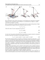
the structures of cells. For example, the cell pictured in Fig-
ure
1.1.1a
is written compactly as
Zn/Zn
2+
,
СГ/AgCl/Ag
(l.l.l)
In
this notation, a slash represents a phase boundary, and a comma separates two compo-
nents
in the same phase. A double slash, not yet used here, represents a phase boundary
whose potential is regarded as a
negligible
component of the overall cell potential. When
a
gaseous phase is involved, it is written adjacent to its corresponding conducting ele-
ment.
For example, the cell in Figure
1.1.1ft
is written schematically as
Pt/H2/H
+
,
СГ/AgCl/Ag
(1.1.2)
The
overall chemical reaction taking place in a cell is made up of two independent
half-reactions,
which describe the real chemical changes at the two electrodes. Each
half-
reaction
(and, consequently, the chemical composition of the system near the electrodes)
Zn
Ag
СГ
Excess
AgCI
Pt
H
2
1.1 Introduction 3
СГ
j
Excess
AgCI
(а)
(Ь)
Figure l.l.l Typical electrochemical cells, (a) Zn metal and Ag wire covered with AgCI immersed
in
a ZnCl2 solution, (b) Pt wire in a stream of H2 and Ag wire covered with AgCI in
HC1
solution.
responds to the interfacial potential difference at the corresponding electrode. Most of the
time,
one is interested in only one of these reactions, and the electrode at which it occurs
is called the
working
(or
indicator)
electrode.
To focus on it, one standardizes the other
half of the cell by using an electrode (called a
reference
electrode)
made up of phases
having essentially constant composition.
The
internationally accepted primary reference is the
standard
hydrogen
electrode
(SHE),
or
normal
hydrogen
electrode
(NHE),
which has all components at unit activity:
Pt/H
2
(a
- l)/H
+
(a = 1, aqueous) (1.1.3)
Potentials
are often measured and quoted with respect to reference electrodes other than
the
NHE, which is not
very
convenient from an experimental standpoint. A common ref-
erence is the
saturated
calomel
electrode
(SCE), which is
Hg/Hg
2
Cl2/KCl (saturated in water) (1.1.4)
Its
potential is
0.242
V vs. NHE. Another is the
silver-silver
chloride
electrode,
Ag/AgCl/KCl (saturated in water) (1.1.5)
with a potential of 0.197 V vs. NHE. It is common to see potentials identified in the litera-
ture
as "vs.
Ag/AgQ"
when this electrode is used.
Since the reference electrode has a constant makeup, its potential is
fixed.
Therefore,
any changes in the cell are ascribable to the working electrode. We say that we observe or
control
the
potential
of the working electrode
with
respect
to the reference, and that is
equivalent to observing or controlling the energy of the electrons within the working elec-
trode
(1, 2). By driving the electrode to more negative potentials (e.g., by connecting a
battery or power supply to the cell with its negative side attached to the working elec-
trode),
the energy of the electrons is raised. They can reach a
level
high enough to transfer
into
vacant electronic states on species in the electrolyte. In that case, a
flow
of electrons
from electrode to solution (a
reduction
current)
occurs (Figure
1.1.2a).
Similarly, the en-
ergy
of the electrons can be lowered by imposing a more positive potential, and at some
point
electrons on solutes in the electrolyte
will
find a more favorable energy on the elec-
trode
and
will
transfer there. Their
flow,
from solution to electrode, is an
oxidation
cur-
rent
(Figure
1.1.2b).
The critical potentials at which these processes occur are related to
the
standard
potentials,
E°, for the specific chemical substances in the system.
4
Chapter
1.
Introduction
and
Overview
of
Electrode Processes
Electrode
Solution
Electrode
Solution
0
Potential
0j
Energy
level
of
electrons
Vacant
MO
Occupied
MO
A
+ e
—>
A
(a)
0
Potential
0l
Electrode
Energy
level
of
electrons
Solution
Electrode
Solution
Vacant
MO
Occupied
MO
A
- e -^ A
+
(b)
Figure
1.1.2
Representation
of (a)
reduction
and (b)
oxidation
process
of a
species,
A, in
solution.
The
molecular
orbitals
(MO) of
species
A
shown
are the
highest occupied
MO and the
lowest
vacant
MO.
These
correspond
in an
approximate
way to the E°s of the A/A~ and A
+
/A
couples,
respectively.
The
illustrated
system
could represent
an
aromatic
hydrocarbon
(e.g.,
9,10-diphenylanthracene)
in an
aprotic solvent
(e.g.,
acetonitrile)
at a
platinum
electrode.
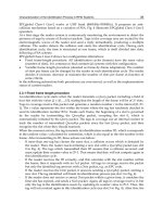
Consider a typical electrochemical experiment where a working electrode and a ref-
erence electrode are immersed in a solution, and the potential difference between the elec-
trodes is varied by means of an external power supply (Figure
1.1.3).
This variation in
potential, £, can produce a current flow in the external circuit, because electrons cross the
electrode/solution interfaces as reactions occur. Recall that the number of electrons that
cross an interface is related stoichiometrically to the extent of the chemical reaction (i.e.,
to the amounts of reactant consumed and product generated). The number of electrons is
measured in terms of the total charge, Q, passed in the circuit. Charge is expressed in
units of coulombs (C), where 1 С is equivalent to 6.24 X 10
18
electrons. The relationship
between
charge and
amount
of
product
formed is given by Faraday's law;
that
is, the pas-
sage of 96,485.4 С causes 1 equivalent of
reaction
(e.g., consumption of 1 mole of
reac-
tant
or
production
of 1 mole of
product
in a one-electron
reaction).
The
current,
/, is the
rate
of flow of coulombs (or
electrons),
where a
current
of 1 ampere (A) is equivalent to 1
C/s.
When one plots the
current
as a function of the
potential,
one obtains a current-poten-
tial (i vs. E) curve. Such curves can be quite informative about the
nature
of the solution
and
the electrodes and about the reactions
that
occur at the interfaces.
Much
of the re-
mainder
of this book deals with how one obtains and interprets such curves.
1.1 Introduction 5
Power
supply
Pt
1МНВГ
-Ag
-AgBr
Figure 1.1.3 Schematic diagram of the
electrochemical cell Pt/HBr(l
M)/AgBr/Ag
attached
to
power supply and meters for obtaining a current-
potential
(i-E)
curve.
Let us now consider the particular cell in Figure 1.1.3 and discuss in a qualitative
way the current-potential curve that might be obtained with it. In Section 1.4 and in later
chapters,
we
will
be more quantitative. We
first
might consider simply the potential we
would measure when a high impedance voltmeter (i.e., a voltmeter whose internal resis-
tance
is so high that no appreciable current
flows
through it during a measurement) is
placed across the cell. This is called the
open-circuit
potential
of the cell.
1
For
some electrochemical cells, like those in Figure
1.1.1,
it is possible to calculate
the
open-circuit potential from thermodynamic data, that is, from the standard potentials
of the half-reactions involved at both electrodes via the Nernst equation (see Chapter 2).
The
key point is that a true equilibrium is established, because a pair of redox forms
linked by a given half-reaction (i.e., a
redox
couple)
is present at each electrode. In Figure
1.1.1/?,
for example, we have H
+
and H
2
at one electrode and Ag and
AgCl
at the other.
2
The
cell in Figure 1.1.3 is different, because an overall equilibrium cannot be estab-
lished. At the
Ag/AgBr
electrode, a couple is present and the half-reaction is
AgBr
+ e
±±
Ag + Br
=
0.0713
Vvs. NHE (1.1.6)
Since
AgBr
and Ag are both solids, their activities are unity. The activity of Br can be
found from the concentration in solution; hence the potential of this electrode (with re-
spect to NHE) could be calculated from the Nernst equation. This electrode is at equilib-
rium. However, we cannot calculate a thermodynamic potential for the Pt/H
+
,Br~
electrode,
because we cannot identify a pair of chemical species coupled by a given
half-
reaction.
The controlling pair clearly is not the
H2,H
+
couple, since no H
2
has been intro-
duced into the cell. Similarly, it is not the O
2
,H
2
O couple, because by leaving O
2
out of
the
cell formulation we imply that the solutions in the cell have been deaerated. Thus, the
Pt
electrode and the cell as a whole are not at equilibrium, and an equilibrium potential
*In
the electrochemical literature, the open-circuit potential is
also
called
the
zero-current
potential
or the
rest
potential.
2
When
a redox couple is present at each electrode and there are no contributions from
liquid
junctions (yet to be
discussed), the open-circuit potential is
also
the
equilibrium
potential.
This is the situation for each
cell
in
Figure
1.1.1.
Chapter
1. Introduction and
Overview
of Electrode Processes
does not
exist.
Even though the open-circuit potential of the cell is not
available
from
thermodynamic
data, we can place it within a potential range, as shown
below.
Let us now consider what occurs when a power supply (e.g., a battery) and a mi-
croammeter
are connected across the cell, and the potential of the Pt electrode is made
more
negative with respect to the
Ag/AgBr
reference electrode. The
first
electrode reac-
tion
that occurs at the Pt is the reduction of protons,
2H
+
+ 2e-*H
2
(1.1.7)
The
direction of electron
flow
is from the electrode to protons in solution, as in Figure
1.12a,
so a reduction (cathodic) current
flows.
In the convention used in this book, ca-
thodic
currents are taken as positive, and negative potentials are plotted to the right.
3
As
shown in Figure
1.1.4,
the onset of current
flow
occurs when the potential of the Pt elec-
trode
is near E° for the
H
+
/H
2
reaction (0 V vs. NHE or -0.07 V vs. the
Ag/AgBr
elec-
trode).
While
this is occurring, the reaction at the
Ag/AgBr
(which we consider the
reference electrode) is the oxidation of Ag in the presence of Br~ in solution to form
AgBr.
The concentration of Br~ in the solution near the electrode surface is not changed
appreciably with respect to the original concentration (1 M), therefore the potential of the
Ag/AgBr
electrode
will
be almost the same as at open circuit. The conservation of charge
requires that the rate of oxidation at the Ag electrode be equal to the rate of reduction at
the
Pt electrode.
When the potential of the Pt electrode is made sufficiently positive with respect to the
reference electrode, electrons cross from the solution phase into the electrode, and the ox-
Pt/H
+
,
1
1
1
1.5
ВГ(1
M)/AgBr/Ag
Onset
of H
+
reduction
on Pt.
\
I
i
/\
L
1 \
/
Onset
of Br"
/
oxidation
on Pt
\y
0
Cathodic
:/
-0.5
Cell
Potential
Anodic
Figure 1.1.4 Schematic current-potential curve for the cell
Pt/H
+
,
Br~(l
M)/AgBr/Ag,
showing
the
limiting proton reduction and bromide oxidation processes. The cell potential is
given
for the Pt
electrode with respect to the Ag electrode, so it is equivalent to £
Pt
(V vs.
AgBr).
Since
^Ag/AgBr
=
0.07
V vs. NHE, the potential axis could be converted to E
Pt
(V vs. NHE) by adding 0.07 V to each
value
of
potential.
3
The
convention of taking / positive for a cathodic current stems from the early
polarograhic
studies,
where
reduction
reactions were usually studied. This convention has continued among many analytical chemists and
electrochemists,
even though oxidation reactions are now studied with equal
frequency.
Other
electrochemists
prefer to take an anodic current as
positive.
When looking over a derivation in the literature
or
examining
a published i-E
curve,
it is important to
decide,
first, which convention is being used
(i.e.,
"Which
way is
up?").
1.1 Introduction 7
idation of Br~ to Br
2
(and Br^~) occurs. An oxidation current, or anodic current, flows at
potentials near the E° of the half-reaction,
Br
2
+ 2e^2Br~ (1.1.8)
which is +1.09 V vs. NHE or +1.02 V vs. Ag/AgBr. While this reaction occurs (right-
to-left) at the Pt electrode, AgBr in the reference electrode is reduced to Ag and Br~ is
liberated into solution. Again, because the composition of the Ag/AgBr/Br~ interface
(i.e.,
the activities of AgBr, Ag, and Br~) is almost unchanged with the passage of modest
currents, the potential of the reference electrode is essentially constant. Indeed, the essen-
tial characteristic of a reference electrode is that its potential remains practically constant
with the passage of small currents. When a potential is applied between Pt and Ag/AgBr,
nearly all of the potential change occurs at the Pt/solution interface.
The background limits are the potentials where the cathodic and anodic currents start
to flow at a working electrode when it is immersed in a solution containing only an elec-
trolyte added to decrease the solution resistance (a supporting electrolyte). Moving the
potential to more extreme values than the background limits (i.e., more negative than the
limit for H
2
evolution or more positive than that for Br
2
generation in the example above)
simply causes the current to increase sharply with no additional electrode reactions, be-
cause the reactants are present at high concentrations. This discussion implies that one can
often estimate the background limits of a given electrode-solution interface by consider-
ing the thermodynamics of the system (i.e., the standard potentials of the appropriate
half-
reactions). This is frequently, but not always, true, as we shall see in the next example.
From Figure
1.1.4,
one can see that the open-circuit potential is not well defined in
the system under discussion. One can say only that the open-circuit potential lies some-
where between the background limits. The value found experimentally will depend
upon trace impurities in the solution (e.g., oxygen) and the previous history of the Pt
electrode.
Let us now consider the same cell, but with the Pt replaced with a mercury electrode:
Hg/H
+
,Br-(l M)/AgBr/Ag (1.1.9)
We still cannot calculate an open-circuit potential for the cell, because we cannot define a
redox couple for the Hg electrode. In examining the behavior of this cell with an applied
external potential, we find that the electrode reactions and the observed current-potential
behavior are very different from the earlier case. When the potential of the Hg is made
negative, there is essentially no current flow in the region where thermodynamics predict
that H
2
evolution should occur. Indeed, the potential must be brought to considerably
more negative values, as shown in Figure
1.1.5,
before this reaction takes place. The ther-
modynamics have not changed, since the equilibrium potential of half-reaction 1.1.7 is in-
dependent of the metal electrode (see Section 2.2.4). However, when mercury serves as
the locale for the hydrogen evolution reaction, the rate (characterized by a heterogeneous
rate constant) is much lower than at Pt. Under these circumstances, the reaction does not
occur at values one would predict from thermodynamics. Instead considerably higher
electron energies (more negative potentials) must be applied to make the reaction occur at
a measurable rate. The rate constant for a heterogeneous electron-transfer reaction is a
function of applied potential, unlike one for a homogeneous reaction, which is a constant
at a given temperature. The additional potential (beyond the thermodynamic requirement)
needed to drive a reaction at a certain rate is called the overpotential. Thus, it is said that
mercury shows "a high overpotential for the hydrogen evolution reaction."
When the mercury is brought to more positive values, the anodic reaction and the po-
tential for current flow also differ from those observed when Pt is used as the electrode.