E 386 90 (2011)
Bạn đang xem bản rút gọn của tài liệu. Xem và tải ngay bản đầy đủ của tài liệu tại đây (201.39 KB, 9 trang )
Designation: E386 − 90 (Reapproved 2011)
Standard Practice for
Data Presentation Relating to High-Resolution Nuclear
Magnetic Resonance (NMR) Spectroscopy1
This standard is issued under the fixed designation E386; the number immediately following the designation indicates the year of
original adoption or, in the case of revision, the year of last revision. A number in parentheses indicates the year of last reapproval. A
superscript epsilon (´) indicates an editorial change since the last revision or reapproval.
1. Scope
magnetic field at which the system operates is called Ho (Note
1) and its recommended unit of measurement is the tesla (T) (1
T = 104 gauss).
2.4.1 The foregoing quantities are approximately connected
by the following relation:
1.1 This standard contains definitions of basic terms,
conventions, and recommended practices for data presentation
in the area of high-resolution resolution nuclear magnetic
resonance (NMR) spectroscopy. Some of the basic definitions
apply to wide-line NMR or to NMR of metals, but in general
it is not intended to cover these latter areas of NMR in this
standard. This version does not include definitions pertaining
to double resonance nor to rotating frame experiments.
νo 5
γ
H
2π o
(1)
where γ = the magnetogyric ratio, a constant for a given
nuclide (Note 2). The amplitude of the magnetic component of
the radio-frequency field is called H1. Recommended units are
millitesla and microtesla.
1.2 The values stated in SI units are to be regarded as
standard. No other units of measurement are included in this
standard.
NOTE 2—This quantity is normally referred to as B by physicists. The
usage of H to refer to magnetic field strength in chemical applications is
so widely accepted that there appears to be no point in attempting to reach
a totally consistent nomenclature now.
NOTE 3—This expression is correct only for bare nuclei and will be only
approximately true for nuclei in chemical compounds, since the field at the
nucleus is in general different from the static magnetic field. The
discrepancy amounts to a few parts in 106 for protons, but may be of
magnitude 1 × 10⁻³ for the heaviest nuclei.
2. Terminology Nomenclature and Basic Definitions
2.1 nuclear magnetic resonance (NMR) spectroscopy—that
form of spectroscopy concerned with radio-frequency-induced
transitions between magnetic energy levels of atomic nuclei.
2.2 NMR apparatus; NMR equipment—an instrument comprising a magnet, radio-frequency oscillator, sample holder,
and a detector that is capable of producing an electrical signal
suitable for display on a recorder or an oscilloscope, or which
is suitable for input to a computer.
2.5 NMR absorption line—a single transition or a set of
degenerate transitions is referred to as a line.
2.6 NMR absorption band; NMR band— a region of the
spectrum in which a detectable signal exists and passes through
one or more maxima.
2.3 high-resolution NMR spectrometer— an NMR apparatus
that is capable of producing, for a given isotope, line widths
that are less than the majority of the chemical shifts and
coupling constants for that isotope.
2.7 reference compound (NMR)—a selected material to
whose signal the spectrum of a sample may be referred for the
measurement of chemical shift (see 2.9).
2.7.1 internal reference (NMR)—a reference compound that
is dissolved in the same phase as the sample.
2.7.2 external reference (NMR)—a reference compound that
is not dissolved in the same phase as the sample.
NOTE 1—By this definition, a given spectrometer may be classed as a
high-resolution instrument for isotopes with large chemical shifts, but may
not be classed as a high-resolution instrument for isotopes with smaller
chemical shifts.
2.4 basic NMR frequency, νo—the frequency, measured in
hertz (Hz), of the oscillating magnetic field applied to induce
transitions between nuclear magnetic energy levels. The static
2.8 lock signal—the NMR signal used to control the fieldfrequency ratio of the spectrometer. It may or may not be the
same as the reference signal.
2.8.1 internal lock—a lock signal which is obtained from a
material that is physically within the confines of the sample
tube, whether or not the material is in the same phase as the
sample (an annulus for the purpose of this definition is
considered to be within the sample tube).
1
This practice is under the jurisdiction of ASTM Committee E13 on Molecular
Spectroscopy and Separation Science and is the direct responsibility of Subcommittee E13.15 on Analytical Data.
Current edition approved Nov. 1, 2011. Published January 2012. Originally
approved in 1969. Last previous edition approved in 2004 as E386 – 90 (2004).
DOI: 10.1520/E0386-90R11.
Copyright © ASTM International, 100 Barr Harbor Drive, PO Box C700, West Conshohocken, PA 19428-2959. United States
1
E386 − 90 (2011)
2.8.2 external lock—a lock signal which is obtained from a
material that is physically outside the sample tube. The
material supplying the lock signal is usually built into the
probe.
3. Types of High-Resolution NMR Spectroscopy
3.1 sequential excitation NMR; continuous wave (CW)
NMR—a form of high-resolution NMR in which nuclei of
different field/frequency ratio at resonance are successively
excited by sweeping the magnetic field or the radio frequency.
3.1.1 rapid scan Fourier transform NMR; correlation
spectroscopy—a form of sequential excitation NMR in which
the response of a spin system to a rapid passage excitation is
obtained and is converted to a slow-passage spectrum by
mathematical correlation with a reference line, or by suitable
mathematical procedures including Fourier transformations.
NOTE 4—An external lock, if also used as a reference, is necessarily an
external reference. An internal lock, if used as a reference, may be either
an internal or an external reference, depending upon the experimental
configuration.
2.8.3 homonuclear lock—a lock signal which is obtained
from the same nuclide that is being observed.
2.8.4 heteronuclear lock—a lock signal which is obtained
from a different nuclide than the one being observed.
3.2 broad-band excitation NMR—a form of high-resolution
NMR in which nuclei of the same isotope but possibly different
chemical shifts are excited simultaneously rather than sequentially.
3.2.1 pulse Fourier transform NMR—a form of broad-band
excitation NMR in which the sample is irradiated with one or
more pulse sequences of radio-frequency power spaced at
uniform time intervals, and the averaged free induction decay
following the pulse sequences is converted to a frequency
domain spectrum by a Fourier transformation.
3.2.1.1 pulse Fourier difference NMR—a form of pulse
Fourier transform NMR in which the difference frequencies
between the sample signals and a strong reference signal are
extracted from the sample response prior to Fourier transformation.
3.2.1.2 synthesized excitation Fourier NMR— a form of
pulse Fourier NMR in which a desired frequency spectrum for
the exciting signal is Fourier synthesized and used to modulate
the exciting radio frequency.
3.2.2 stochastic excitation NMR—a form of broad band
excitation NMR in which the nuclei are excited by a range of
frequencies produced by random or pseudorandom noise
modulation of the carrier, and the frequency spectrum is
obtained by Fourier transforming the correlation function
between the input and output signals.
3.2.3 Hadamard transform NMR—a form of broad band
excitation NMR in which the phase of the excitation signal is
switched according to a binary pseudorandom sequence, and
the correlation of the input and output signals by a Hadamard
matrix yields an interference pattern which is then Fouriertransformed.
2.9 chemical shift, δ—the defining equation for δ is the
following:
δ5
∆ν
3 106
νR
(2)
where νR is the frequency with which the reference substance
is in resonance at the magnetic field used in the experiment and
∆ν is the frequency of the subject line minus the frequency of
the reference line at constant field. The sign of ∆ν is to be
chosen such that shifts to the high frequency side of the
reference shall be positive.
2.9.1 If the experiment is done at constant frequency (field
sweep) the defining equation becomes
δ5
S
∆ν
∆ν
3 12
νR
νR
D
3 10
(3)
2.9.2 In case the experiment is done by observation of a
modulation sideband, the audio upper or lower sideband
frequency must be added to or subtracted from the radio
frequency.
2.10 spinning sidebands—bands, paired symmetrically
about a principal band, arising from spinning of the sample in
a field (dc or rf) that is inhomogeneous at the sample position.
Spinning sidebands occur at frequencies separated from the
principal band by integral multiples of the spinning rate. The
intensities of bands which are equally spaced above and below
the principal band are not necessarily equal.
2.11 satellites—additional bands spaced nearly symmetrically about a principal band, arising from the presence of an
isotope of non-zero spin which is coupled to the nucleus being
observed. An isotope shift is normally observed which causes
the center of the satellites to be chemically shifted from the
principal band. The intensity of the satellite signal increases
with the abundance of the isotope responsible.
4. Operational Definitions
4.1 Definitions Applying to Sequential Excitation (CW)
NMR:
4.1.1 field sweeping (NMR)—systematically varying the
magnetic field strength, at constant applied radio-frequency
field, to bring NMR transitions of different energies successively into resonance, thereby making available an NMR
spectrum consisting of signal intensity versus magnetic field
strength.
4.1.2 frequency sweeping (NMR)—systematically varying
the frequency of the applied radio frequency field (or of a
modulation sideband, see 4.1.4), at constant magnetic field
2.12 NMR line width—the full width, expressed in hertz
(Hz), of an observed NMR line at one-half maximum height
(FWHM).
2.13 spin-spin coupling constant (NMR), J—a measure,
expressed in hertz (Hz), of the indirect spin-spin interaction of
different magnetic nuclei in a given molecule.
NOTE 5—The notation n JAB is used to represent a coupling over n bonds
between nuclei A and B. When it is necessary to specify a particular
isotope, a modified notation may be used, such as, 3J (15NH).
2
E386 − 90 (2011)
strength, to bring NMR transitions of different energies successively into resonance, thereby making available an NMR
spectrum consisting of signal intensity versus applied radio
frequency.
4.1.3 sweep rate—the rate, in hertz (Hz) per second at which
the applied radio frequency is varied to produce an NMR
spectrum. In the case of field sweep, the actual sweep rate in
microtesla per second is customarily converted to the equivalent in hertz per second, using the following equation:
∆ν
γ ∆H
5
·
∆t
2π ∆t
NOTE 9—Other parameters, such as rate of roll-off, width of passband,
or width and rejection of center frequency in case of a notch filter, may be
required to define filter characteristics adequately.
4.2.10 data acquisition rate; sampling rate; digitizing
rate—the number of data points recorded per second.
4.2.11 dwell time—the time between the beginning of sampling of one data point and the beginning of sampling of the
next successive point in the FID.
4.2.11.1 aperture time—the time interval during which the
sample-and-hold device is receptive to signal information. In
most applications of pulse NMR, the aperture time is a small
fraction of the dwell time.
(4)
4.1.4 modulation sidebands—bands introduced into the
NMR spectrum by, for example, modulation of the resonance
signals. This may be accomplished by modulation of the static
magnetic field, or by either amplitude modulation or frequency
modulation of the basic radio frequency.
4.1.5 NMR spectral resolution—the width of a single line in
the spectrum which is known to be sharp, such as, TMS or
benzene (1H). This definition includes sample factors as well as
instrumental factors.
4.1.6 NMR integral (analog)—a quantitative measure of the
relative intensities of NMR signals, defined by the areas of the
spectral lines and usually displayed as a step function in which
the heights of the steps are proportional to the areas (intensities) of the resonances.
NOTE 10—Sampling Time has been used with both of the above
meanings. Since the use of this term may be ambiguous, it is to be
discouraged.
4.2.12 detection method—a specification of the method of
detection.
4.2.12.1 single-phase detection—a method of operation in
which a single phase-sensitive detector is used to extract signal
information from a FID.
4.2.12.2 quadrature detection—a method of operation in
which dual phase-sensitive detection is used to extract a pair of
FID’s which differ in phase by 90°.
4.2.13 spectral width—the frequency range represented
without foldover. (Spectral width is equal to one half the data
acquisition rate in the case of single-phase detection; but is
equal to the full data acquisition rate if quadrature detection is
used.)
4.2.14 foldover; foldback—the appearance of spurious lines
in the spectrum arising from either (a) limitations in data
acquisition rate or (b) the inability of the spectrometer detector
to distinguish frequencies above the carrier frequency from
those below it.
4.2 Definitions Applying to Multifrequency Excitation
(Pulse) NMR:
4.2.1 pulse (v)—to apply for a specified period of time a
perturbation (for example, a radio frequency field) whose
amplitude envelope is nominally rectangular.
4.2.2 pulse (n)—a perturbation applied as described above.
4.2.3 pulse width—the duration of a pulse.
4.2.4 pulse flip angle—the angle (in degrees or radians)
through which the magnetization is rotated by a pulse (such as
a 90-deg pulse or π/2 pulse).
4.2.5 pulse amplitude—the radio frequency field, H1, in
tesla.
NOTE 11—These two meanings of foldover are in common use. Type (a)
is often termed “aliasing.” Type (b) foldover is obviated by the use of
quadrature detection.
4.2.15 data acquisition time—the period of time during
which data are acquired and digitized; equal numerically to the
product of the dwell time and the number of data points
acquired.
4.2.16 computer-limited spectral resolution—the spectral
width divided by the number of data points.
Note—This will be a measure of the observed line width
only when it is much greater than the spectral resolution
defined in 4.1.5.
4.2.17 pulse sequence—a set of defined pulses and time
spacings between these pulses.
NOTE 6—This may be specified indirectly, as described in 8.3.2.
4.2.6 pulse phase—the phase of the radio frequency field as
measured relative to chosen axes in the rotating coordinate
system.2
NOTE 7—The phase may be designated by a subscript, such as, 90°x or
(π/2)x.
4.2.7 free induction decay (FID)—the time response signal
following application of an r-f pulse.
4.2.8 homogeneity spoiling pulse; homo-spoil pulse; inhomogenizing pulse—a deliberately introduced temporary deterioration of the homogeneity of the magnetic field H.
4.2.9 filter bandwidth; filter passband— the frequency
range, in hertz, transmitted with less than 3 dB (50 %)
attenuation in power by a low-pass filter.
NOTE 12—There may be more than one way of expressing a sequence,
for example, a series (90°, τ)n may be one sequence of n pulses or n
sequences each of the form (90°,τ ).
4.2.18 pulse interval—the time between two pulses of a
sequence.
4.2.19 waiting time—the time between the end of data
acquisition after the last pulse of a sequence and the initiation
of a new sequence.
NOTE 8—On some commercial instruments, filter bandwidth is defined
in a slightly different manner.
NOTE 13—To ensure equilibrium at the beginning of the first sequence,
the software in some NMR systems places the waiting time prior to the
2
For a discussion of the rotating coordinate system, see Abragam, “Principles of
Nuclear Magnetism,” Oxford, 1961, pp. 19ff.
3
E386 − 90 (2011)
δ = 5.00 or δ 5.00. Alternative forms, such as δ = 5.00 ppm or
shift = 5.00 δ shall not be used.
initiation of the first pulse of the sequence.
4.2.20 acquisition delay time—the time between the end of
a pulse and the beginning of data acquisition.
4.2.21 sequence delay time; recovery interval—the time
between the last pulse of a pulse sequence and the beginning of
the succeeding (identical) pulse sequence. It is the time
allowed for the nuclear spin system to recover its
magnetization, and it is equal to the sum of the acquisition
delay time, data acquisition time, and the waiting time.
4.2.22 sequence repetition time—the period of time between
the beginning of a pulse sequence and the beginning of the
succeeding (identical) pulse sequence.
4.2.23 pulse repetition time—the period of time between
one r-f pulse and the succeeding (identical) pulse; used instead
of sequence repetition time when the “sequence” consists of a
single pulse.
4.2.24 inversion-recovery sequence—a sequence that inverts the nuclear magnetization and monitors its recovery, such
as (180°,τ , 90°), where τ is the pulse interval.
4.2.25 saturation-recovery sequence—a sequence that saturates the nuclear magnetization and monitors its recovery, such
as the sequence (90°, homogeneity-spoiling pulse, τ, 90°, T,
homogeneity-spoiling pulse) or the sequence (90°)n, τ, 90°, T,
where (90°)n represents a rapid burst of 90° pulses.
4.2.26 progressive saturation sequence— the sequence 90°,
(τ, 90°)n, where n may be a large number, and data acquisition
normally occurs after each pulse (except possibly the first three
or four pulses).
4.2.27 spin-echo sequence—the sequence 90°, τ, 180°
4.2.28 Carr-Purcell (CP) sequence—the sequence 90°, τ,
180°, (2τ, 180°)n, where n can be a large number.
4.2.29 Carr-Purcell time—the pulse interval 2τ between
successive 180° pulses in the Carr-Purcell sequence.
4.2.30 Meiboom-Gill sequence; CPMG sequence—the sequence 90°x, τ, 180°y, (2τ, 180°y)n.
4.2.31 spin-locking sequence—the sequence 90°x, (SL)y,
where SL denotes a “long” pulse (often measured in milliseconds or seconds, rather than microseconds) and H (lock) >> H
(local).
4.2.32 zero filling—supplementing the number of data
points in the time response signal with trailing zeroes before
Fourier transformation.
4.2.33 partially relaxed Fourier transform (PRFT) NMR—a
set of multiline FT spectra obtained from an inversion-recovery
sequence and designed to provide information on spin-lattice
relaxation times.
4.2.34 NMR integral (digital)—the integrals (see 4.1.6) of
pulse-Fourier transform spectra or of digitized CW spectra,
obtained by summing the amplitudes of the digital data points
that define the envelope of each NMR band. The results of
these summations are usually displayed either as a normalized
total number of digital counts for each band, or as a step
function (running total of digital counts) superimposed on the
spectrum.
5.2 The unit used for line positions should be hertz.
5.3 The dimensionless and frequency scales should have a
common origin.
5.4 The standard sweep direction should be from high to
low radio frequency (low to high applied magnetic field).
5.5 The standard orientation of spectra should be with low
radio frequency (high field) to the right.
5.6 Absorption mode peaks should point up.
6. Referencing Procedures and Substances
6.1 General:
6.1.1 Whenever possible, in the case of proton and
carbon-13 spectra, the chemical shift scale should be tied to an
internal reference.
6.1.2 In case an external reference is used, either a coaxial
tube or a capillary tube is generally adequate.
6.1.3 For nuclei other than protons or 13 C, for which
generally agreed-upon reference substances do not yet exist, it
is particularly important to report the reference material and
referencing procedure fully, including separations in hertz and
the spectrometer radio frequency when it is known.
6.2 NMR Reference Substances for Proton Spectra:
6.2.1 The primary internal reference for proton spectra in
nonaqueous solution shall be tetramethylsilane (TMS). A
concentration of 1 % or less is preferred.
6.2.2 The position of the tetramethylsilane resonance is
defined as exactly zero.
6.2.3 The recommended internal reference for proton spectra in aqueous solutions is the sodium salt of 2,2,3,3tetradeutero-4,4-dimethyl-4-silapentanoic acid (TSP-d4). Its
chemical shift is assigned the value zero.
6.2.4 The numbers on the dimensionless (shift) scale to high
frequency (low field) of TMS shall be regarded as positive.
6.3 NMR Reference Substances for Nuclei Other than Protons:
6.3.1 For all nuclei the numbers on the dimensionless (shift)
scale to high frequency (low field) from the reference substance shall be positive. In the interim, until this proposal has
been fully adopted, the sign convention used should be
explicitly given.
NOTE 14—The existing literature on NMR contains examples of both
the sign convention given above and its opposite. It seems desirable to
adopt a uniform convention for all nuclei, and the convention recommended herein is already widely used in both proton and 13C NMR. The
recommended convention will result in assigning the most positive
numerical value to the transition of highest energy.
6.3.2 The primary internal reference for 13C spectra of
nonaqueous solutions shall be tetramethylsilane (TMS). For
aqueous solutions, secondary standards such as dioxane have
been found satisfactory. When such standards are used the line
positions and chemical shifts should be reported with reference
to TMS, and the conversion factor should be stated explicitly.
5. NMR Conventions
5.1 The dimensionless scale used for chemical shifts for any
nucleus shall be termed the δ scale. The correct usage is
4
E386 − 90 (2011)
6.3.3 The primary external reference for boron spectra (10B
and 11 B) shall be boron trifluoride-diethyletherate
[(C2H5)2O:BF3].
6.3.4 The primary external reference for 31P spectra shall be
phosphorus trioxide (P4O6).
6.3.5 Specific recommendations for nuclei other than those
mentioned above are not offered here. The following guidelines
should be used: If previous work on the nucleus under study
exists, any earlier reference should be used unless there are
compelling reasons to choose a new reference. A reference
substance should have a sharp line spectrum if possible. A
singlet spectrum is preferred. A reference substance should be
chosen to have a resonance at low frequency (high field) so far
as possible, in order that the majority of chemical shifts will be
of positive sign. Internal references should be avoided unless it
is possible to include a study of solvent effects on chemical
shift.
concentration of ethylbenzene appropriate to the sensitivity of
the instrument under test, such that the S/N as measured on the
methylene quartet is 25:1. State the determined S/N as “equivalent one percent ethylbenzene sensitivity.” Carry out the
measurement using the following conditions:
Spectral width
Data acquisition time
Flip angle
Analog filter
Detection method
Equilibration delay
1H
≡ 0)
0 to 10 ppm (δ TMS
$0.4 s
90°
appropriate for method of detection
specify (for example, single phase, SSB, QPD)
60 s
Following the data acquisition, multiply the data by a
decaying exponential function of the form e −t/A, where A is
equivalent to a T2 contribution. A may be expressed as a time
constant in units of seconds, or, alternatively, the line broadening (LB) resulting from the exponential multiplication may
be expressed in units of hertz (Hz). For the measurement,
A = 0.3 or LB = 1 Hz. Perform no data smoothing after
transformation. Plot the resulting absorption mode spectrum
over the full 0 to 10 ppm. Measure S/N on a plot expansion
covering the range of 2 to 6 ppm, in which the methylene
quartet is plotted to fill the chart paper as closely as practical.
Use sufficient vertical amplitude to obtain a peak-to-peak noise
measurement greater than 2 cm. Measure peak-to-peak noise
over the 4 to 6 ppm region on the same trace or calculate rms
noise by computer (see Note 2). The S/N is then calculated on
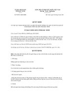
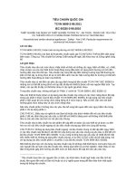
the strongest line in the quartet as follows (see Fig. 1):
7. Recommended Practice for Signal-to-Noise
Determination in Fourier Transform NMR
7.1 General—This section gives the recommended practice
for signal-to-noise ratio (S/N) determination in three specific
situations: (a) proton single pulse mode; (b) carbon-13 single
pulse mode; and (c) carbon-13 multiple pulse mode.
NOTE 15—Some of the materials recommended for use in this section
are known to present health hazards if used improperly. Anyone making
up solutions containing benzene, dioxane, or chloroform should consult
and abide by OSHA regulations 29CFR 1910.1000 (solvents) and 29CFR
1910.1028 (benzene).
@ ~ signal intensity! / ~ peak 2 to 2 peak noise! # 3 2.5 5 S/N (5)
NOTE 16—The true rms noise can be calculated by computer and used
in the S/N determination. Since peak-to-peak noise is approximately five
times rms noise, rather than 2.5 times, the rms noise must be doubled to
obtain a comparable S/N. When this is done, it is felt that the S/N
determined by computer should be reliable and less subject to human error
than the alternate method of estimating peak-to-peak noise from a chart
recording. The computer program should do the following:
7.2 Proton Single Pulse Mode:
7.2.1 Sample—Dilute ethylbenzene in CDCl3.
7.2.2 Measurement—Proton signal-to-noise ratio is measured using a single pulse of radio-frequency power applied to
a dilute solution of ethylbenzene in CDCl3. Choose the
FIG. 1 Typical S/N Measurement on the Proton Signal in Dilute Ethylbenzene
5
E386 − 90 (2011)
(a) Select the region in which noise is to be measured as
specified in the above test.
(b) Obtain the algebraic mean of all the observed points in
this region, and subtract the mean from each point (zero-order
correction).
(c) If the base line slopes, a first order correction may be
made by using a standard least-squares method to obtain the
slope and intercept of the baseline, then subtracting each
calculated point from the corresponding observed point.
(d) Corrections calculated on the noise in the specified
region of the spectrum should be applied to that region and also
to the spectral region containing the signal.
(e) Form the sum of the squares of each amplitude (point),
corrected as described previously, divide by one less than the
number of points in the region, and take the square root. This
is the rms noise.
rms noise 5 @ ~
( @ amplitude#
2
! / ~ N 2 1 ! # 1/2
Following the data acquisition, multiply the data by a
decaying exponential function of the form e−t/A, where A is
equivalent to a T2 contribution. A may be expressed as a time
constant in units of seconds, or, alternatively, the line broadening (LB) resulting from exponential multiplication may be
expressed in units of hertz (Hz). For the measurement, A = 0.3
or LB = 1 Hz. Perform no data smoothing after transformation.
Plot the resulting absorption mode spectrum over the full 0 to
200 ppm chemical shift range. Plot the C6D6 triplet to fill the
vertical range of the chart paper as closely as practical. Use
sufficient vertical amplitude to obtain a peak-to-peak noise
measurement greater than 2 cm. Signal-to-noise is to be
measured as:
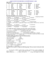
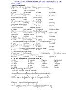
@ ~ average triplet intensity! / ~ peak 2 to 2 peak noise! # 3 2.5 5 S/N
(7)
Measure the peak-to-peak noise between the C6D6 and
dioxane triplets, specifically between and inclusive of 80 and
120 ppm on the 13C chemical shift scale, or calculate rms noise
by computer (see Note 2 and Fig. 2).
7.3.3 Characteristics of the Proposed Standard:
7.3.3.1 The S/N of the C6D6 triplet is low enough to permit
a plot from which both signal and noise may be measured. For
a full scale vertical display of the C6D6 triplet, the peak-to-peak
noise amplitude should be adequately measured and have two
significant figures. (For those spectrometers with very high
sensitivity, noise would still have to be blown up to at least 2
cm peak-to-peak in a separate trace of the same transformed
data.)
7.3.3.2 The C6D6 triplet has linewidth of 14 Hz under these
conditions, reasonably independent of magnet resolution, permitting easy tune up and small 4 K data table for the
measurement.
7.3.3.3 The C6D6 S/N can be measured in the presence of or
absence of high power proton decoupling facilitating servicing
diagnostic procedures. It is particularly valuable in diagnosing
decoupler-caused noise contributions.
7.3.3.4 The broad lines of the C6D6 result from long-range
13
C-2H coupling and thus the linewidth is not field-dependent.
7.3.3.5 C6D6 has no nuclear Overhauser enhancement
(NOE).
7.3.3.6 The reference material is widely available and can
serve as an internal 2H lock.
7.3.3.7 The C6D6 S/N is independent of applied lock power
in normal locking power range up to and beyond saturation of
the deuterium signal.
7.3.3.8 The C6D6 S/N is temperature independent over
normal working temperatures.
7.3.3.9 The dioxane serves several purposes: ready reference to prior data; a conveniently short T1 (<10 s); under
decoupled conditions it possesses a strong signal serving for
γH1/2π measurement by means of a 90° pulse determination;
under off-resonance conditions its residual 13C-1H coupling
can serve to measure γ H2/2π; the decoupled singlet can be
used to measure resolution in terms of full linewidth at
half-height, also line shape and spinning sidebands; and under
coupled conditions and longer acquisition times, it can provide
a coupled spectrum with long-range couplings. The strong
(6)
No other processing should be done; in particular, points that
appear to be extreme should not be deleted. S/N becomes
simply (signal intensity/2)/(rms noise).
7.2.3 Discussion—The 1 % ethylbenzene S/N measurement
is a widely used method for 1H S/N both in CW and FT NMR.
Although presenting few difficulties in CW work, the typical
samples used in FT NMR do present some problems which we
hope to avoid using this procedure.
7.2.3.1 The 1 % concentration traditionally employed generates a very high S/N on modern FT spectrometers, particularly at very high magnetic field strengths.
7.2.3.2 TMS is usually present in standard samples at the
1 % level. This causes a very strong signal which can lead to an
erroneous S/N measurement.
7.2.3.3 The variety of sample tube sizes and S/N values has
made it inconvenient to use a uniform concentration. The
solution(s) should be made up by volume composition at 25°C
using good volumetric practice. Suggested solutions:
No.
1
2
3
Ethylbenzene, %
3.0
1.0
1.0
4
5
6
7
0.33
0.10
0.033
0.010
TMS, % (Note 3)
0.3
0.1
1.0 (also valuable for CW
TMS-locked spectrometers)
0.03
0.01
0.003
0.001
NOTE 17—The TMS is added for a reference material.
7.3 Carbon-13 Single Pulse Mode:
7.3.1 Sample—60 %C6D6(>98atom %D),40 % p-dioxane
(v/v).
7.3.2 Measurement—Measure carbon-13 signal-to-noise ratio on the benzene carbon signal in a solution of 60 %
perdeuterobenzene– 40 % p-dioxane, with the spectrometer
locked to the deuterium in the sample, using the following
conditions:
Spectral width
Data acquisition time
Flip angle
Analog filter
Detection method
Equilibration delay
Decoupler
13
C
≡ 0 ppm)
0 to 200 ppm (δ TMS
$0.4 s
90°
appropriate for method of detection
specify (for example, single phase, SSB, QPD)
300 s
off
6
E386 − 90 (2011)
FIG. 2 Typical S/N Measurement on Single Pulse
13
C Spectrum of C6D6-Dioxane Mixture
time and weighting function. If more than 0.5-s acquisition is
used with a less severe weighting function than above, the fine
structure from the long-range coupling becomes visible. While
no problem for the experienced spectroscopist, this can be and
has been confusing to inexperienced users.
7.3.4.2 In summary, the sample in 7.3 for S/N measurement
is recommended particularly when comparing instruments in
different laboratories. For use within a laboratory by knowledgeable operators, ethylbenzene still offers a practical sample
for simultaneous checking of S/N, resolution and decoupling
efficiency. The adoption of an intrinsic S/N sample such as that
described above also identifies the need for separate measurement of resolution andγ H2/2π to more completely characterize
the performance of an FT spectrometer on 13C. In addition, this
measurement is understood to measure only intrinsic sensitivity and not the sensitivity of a time-averaged spectrum on a
“routine” sample.
signal available from decoupled dioxane permits facile tests of
decoupler gating through measurement of the NOE via “Suppressed Overhauser” gating schemes vs use of coupled dioxane
as the base point for calculating the NOE. The short T1 of
dioxane allows routine check of automatic T1 programs and
calculations.
7.3.4 Discussion—The proposed measurement is possible
and convenient on any modern FT instrument. This method
ensures that the maximum available S/N is obtained, thus
preventing confusion in parameter choice, particularly in the
case of the exponential weighting. A new standard is necessary
in view of the difficulty in widespread reliable use of the 90 %
ethylbenzene sample previously used. The natural linewidths
of the ethylbenzene lines are less than 0.1 Hz requiring
exacting field homogeneity to obtain maximum resolution. The
narrow lines also demand long data acquisition times in each
FID to define the lines adequately. Since ethylbenzene S/N is
measured on a decoupled protonated carbon signal, decoupler
power, modulation efficiency, and offset are all factors in
determining S/N. The S/N for most spectrometers is >100:1 for
90 % ethylbenzene making noise measurements the primary
factor in the derived S/N.
7.3.4.1 Dioxane has been proposed for the S/N sample but it
has some serious drawbacks in addition to several advantages
shared with deuterobenzene. Its T1 is dipole-dipole dominated
and has full NOE in the decoupled experiment. It is easily
possible to have residual NOE in a coupled spectrum by not
waiting long enough for the NOE to decay away prior to the
sampling pulse. Although deuterobenzene has the common
requirement of sufficient equilibration delay the error is always
on the side of lower S/N, whereas dioxane’s apparent S/N can
be up to a factor of three greater than that assumed by simple
inspection of the spectrum. This makes comparison of intrinsic
S/N susceptible to error. The addition of dioxane to the 40 %
level provides all the advantages listed above for routine tuning
up and quick S/N checking, while the C6D6 permits an absolute
measurement. The other major disadvantage of dioxane is the
dependence of the character of the spectrum on acquisition
7.4 Carbon-13 Multiple Pulse Mode:
7.4.1 Sample—0.1 M Sucrose in D2O equilibrated with
toluene. Dissolve 3.423 g of sucrose (stored at a relative
humidity of 50 % or less; NBS SRM sucrose is satisfactory) in
about 90 cc of D2O in a 100-cc volumetric flask, then dilute to
the mark at 25°C with D2O after all the sucrose is dissolved.
Add 0.05 ml of toluene as a preservative.
7.4.2 Measurement—Carry out the measurement in the
multiple-pulsed mode locked to the internal D2O using the
following conditions:
Spectral width
Data acquisition time
Flip angle
Analog filter
Detection method
Pulse repetition rate
1
H decoupler
1
H decoupler frequency
1
H decoupler modulation mode
7
13C
≡ 0)
0 to 200 ppm (δTMS
$0.4 s
90°
appropriate for method of detection
specify (for example, single phase,
SSB, QPD)
1 pulse/s
broadband
centered at 5 ± 1 ppm in the 1H
spectrum
specify (for example, noise, square wave,
etc.)
E386 − 90 (2011)
1
H decoupler modulation
frequency
Number of transients
Operating temperature
experimental time, typically 20 min, while still running long
enough to simulate normal experiments adequately.
7.4.3.2 Decoupling efficiency is another highly variable
element in “routine sensitivity.” It certainly determines the
ultimate sensitivity in the 90 % ethylbenzene sensitivity test
(magnet homogeneity permitting). For this reason ethylbenzene is unsuitable for an absolute sensitivity determination.
Yet, it is necessary to include the decoupler in sensitivity
considerations since a poorly operating decoupler can be the
main determinant in apparent sensitivity. Thus, proper consideration must be given not only to intrinsic sensitivity but also
to “routine” sensitivity in characterizing spectrometer performance.
specify
4000 for 5-mm sample size
1000 for 10 to 12-mm sample size
100 for >12-mm sample size
specify
Following the data acquisition, multiply the data by a
decaying exponential function of the form e−t/A, where A is
equivalent to a T2 contribution. A may be expressed as a time
constant in units of seconds, or, alternatively, the line broadening (LB) resulting from the exponential multiplication may
be expressed in units of Hz. For the measurement, A = 0.3 or
LB = 1.0 Hz. Perform no data smoothing after transformation.
Plot the resulting absorption mode spectrum over the full 200
ppm chemical shift range. Plot the spectrum to fill the vertical
range of the chart paper as closely as practical. Measure the
peak-to-peak noise between 120 and 140 ppm of the spectral
window or calculate rms noise by computer (see Note 2). For
those spectrometers with very high sensitivity, noise may have
to be blown up to at least 2 cm peak-to-peak in a separate trace
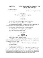
of the same transformed data. Measure signals Nos. 2, 3, 9, and
12 (identified on Fig. 3) and calculate S/N as follows:
@ ~ 21319112! / ~ peak 2 to 2 peak noise! # 3 0.625 5 S/N
8. Presentation of NMR Data and Spectrometer
Parameters
8.1 General—The following should be specified whenever
NMR data are published:
8.1.1 Nucleus observed. In cases where possible ambiguity
exists, the isotope must be specified, for example, 14N, 11B. In
other cases the isotope may be specified, even though
superfluous, such as, 19F, 31P.
8.1.2 Name of solvent and concentration of solution.
8.1.3 Name of external reference, or name and concentration of internal reference, as applicable.
8.1.4 Temperature of sample and how measured.
8.1.5 Procedure used for measuring peak positions.
8.1.6 Radio frequency at which measurements were made.
8.1.7 Magnitude of radio frequency field (see 2.4), or
assurance that saturation of the signal has not occurred (in the
case of CW spectra), or both.
8.1.8 Mathematical operations used to analyze the spectra.
In cases where a computer program has been used to assist in
the analysis of the spectrum, the following information should
be included: Identification/source of program, number of lines
(8)
7.4.3 Discussion—This measurement permits evaluation of
sensitivity under “typical” conditions; that is, the decoupler is
on and many transients are obtained. In addition to a knowledge of the basic, or intrinsic, 13C sensitivity as measured in
the C6D6 test, it is extremely important to evaluate the long
term sensitivity as reflected in a proton-decoupled, timeaveraged spectrum. The type and quality of the decoupling, as
well as long term and short term instabilities in any instrument
element, can profoundly affect sensitivity. This test is designed
to monitor this performance.
7.4.3.1 Sucrose is chosen because of its widespread
availability, purity, low cost, stability (in toluene equilibrated
water) and spectral characteristics. Among these are the reasonable (1 Hz) linewidths, short T1s, and full NOE. The
number of transients is chosen to provide a reasonable total
FIG. 3 Typical S/N Measurement on Accumulated
8
13
C Spectrum of 0.1 M Sucrose in D2O
E386 − 90 (2011)
8.3.4 Spectral width (or data acquisition rate or dwell time).
8.3.5 Data acquisition time (and acquisition delay time if
relevant).
8.3.6 Pulse repetition time and number of pulses if the“
sequence” consists of a single pulse.
8.3.7 Description of pulse sequence including (a) common
name or details of pulses and phases, (b) sequence repetition
time, (c) pulse intervals, (d) waiting time, (e) number of
sequences, and (f) the specific pulse intervals during which
data are acquired.
8.3.8 Quadrature phase detection, if used.
8.3.9 Number of data points Fourier transformed (it is
desirable to indicate specifically whether zero filling is used).
8.3.10 The time constant of exponential weighting function
(exponential filter), if used.
8.3.11 Details of apodization or other weighting of the time
response signal.
8.3.12 Details of any other data processing such as spectral
smoothing, baseline corrections, etc.
8.3.13 Details of systematic noise reduction, if used.
8.3.14 Relation of pulse frequency to observed frequencies.
fitted, identity of parameters varied, rms deviation of all lines,
estimated precision of fitted parameters, and maximum deviation of worst line.
8.1.9 Numbers on the frequency scale (if used). They should
increase from low to high frequency (high to low applied field
if field sweep is used).
8.2 When CW spectra are published the following information should be included:
8.2.1 Sweep rate.
8.2.2 Values of both r-f fields when spin decoupling or
double resonance is employed.
8.2.3 The shifts and couplings obtained from the spectra
should be reported when available, the former in dimensionless units (ppm) and the latter in frequency units (hertz).
8.3 Pulse-Fourier Transform Spectra— For high-resolution
pulse-Fourier transform experiments, all of the following that
are applicable should be specified:
8.3.1 Pulse flip angle used.
8.3.2 90° pulse width, or pulse amplitude.
NOTE 18—Both 8.3.1 and 8.3.2 must always be specified. They may be
given indirectly, for example, as pulse width used and as pulse width for
a 90° pulse for the nucleus being studied.
8.3.3 Bandwidth and rolloff characteristics of all limiting
filters (low-pass and crystal filters). Usually given as bandwidth (see 4.2.9) and type (such as, a 4-pole Butterworth).
9. Keywords
9.1 molecular spectroscopy; nuclear magnetic resonance
ASTM International takes no position respecting the validity of any patent rights asserted in connection with any item mentioned
in this standard. Users of this standard are expressly advised that determination of the validity of any such patent rights, and the risk
of infringement of such rights, are entirely their own responsibility.
This standard is subject to revision at any time by the responsible technical committee and must be reviewed every five years and
if not revised, either reapproved or withdrawn. Your comments are invited either for revision of this standard or for additional standards
and should be addressed to ASTM International Headquarters. Your comments will receive careful consideration at a meeting of the
responsible technical committee, which you may attend. If you feel that your comments have not received a fair hearing you should
make your views known to the ASTM Committee on Standards, at the address shown below.
This standard is copyrighted by ASTM International, 100 Barr Harbor Drive, PO Box C700, West Conshohocken, PA 19428-2959,
United States. Individual reprints (single or multiple copies) of this standard may be obtained by contacting ASTM at the above
address or at 610-832-9585 (phone), 610-832-9555 (fax), or (e-mail); or through the ASTM website
(www.astm.org). Permission rights to photocopy the standard may also be secured from the Copyright Clearance Center, 222
Rosewood Drive, Danvers, MA 01923, Tel: (978) 646-2600; />
9