Astm e 1067 e 1067m 11
Bạn đang xem bản rút gọn của tài liệu. Xem và tải ngay bản đầy đủ của tài liệu tại đây (587.61 KB, 16 trang )
Designation: E1067/E1067M − 11
Standard Practice for
Acoustic Emission Examination of Fiberglass Reinforced
Plastic Resin (FRP) Tanks/Vessels1
This standard is issued under the fixed designation E1067/E1067M; the number immediately following the designation indicates the year
of original adoption or, in the case of revision, the year of last revision. A number in parentheses indicates the year of last reapproval.
A superscript epsilon (´) indicates an editorial change since the last revision or reapproval.
1. Scope*
D5436 Specification for Cast Poly(Methyl Methacrylate)
Plastic Rods, Tubes, and Shapes
E543 Specification for Agencies Performing Nondestructive
Testing
E650 Guide for Mounting Piezoelectric Acoustic Emission
Sensors
E750 Practice for Characterizing Acoustic Emission Instrumentation
E1316 Terminology for Nondestructive Examinations
E2075 Practice for Verifying the Consistency of AE-Sensor
Response Using an Acrylic Rod
E2374 Guide for Acoustic Emission System Performance
Verification
2.2 ANSI/ASNT Standards:
SNT-TC-1A Recommended Practice for Nondestructive
Testing Personnel Qualification and Certification3
ANSI/ASNT CP-189 Standard for Qualification and Certification of Nondestructive Testing Personnel3
2.3 AIA Standard:
NAS-410 Certification and Qualification of Nondestructive
Personnel (Quality Assurance Committee)4
1.1 This practice covers acoustic emission (AE) examination or monitoring of fiberglass-reinforced plastic (FRP) tanksvessels (equipment) under pressure or vacuum to determine
structural integrity.
1.2 This practice is limited to tanks-vessels designed to
operate at an internal pressure no greater than 1.73 MPa
absolute [250 psia] above the static pressure due to the internal
contents. It is also applicable for tanks-vessels designed for
vacuum service with differential pressure levels between 0 and
0.10 MPa [0 and 14.5 psi].
1.3 This practice is limited to tanks-vessels with glass
contents greater than 15 % by weight.
1.4 This practice applies to examinations of new and inservice equipment.
1.5 Units—The values stated in either SI units or inchpound units are to be regarded as standard. The values stated in
each system may not be exact equivalents; therefore, each
system shall be used independently of the other. Combining
values from the two systems may result in non-conformance
with the standard.
1.6 This standard does not purport to address all of the
safety concerns, if any, associated with its use. It is the
responsibility of the user of this standard to establish appropriate safety and health practices and determine the applicability of regulatory limitations prior to use. (For more specific
safety precautionary information see 8.1.)
3. Terminology
3.1 Complete definitions of terms related to plastics and
acoustic emission will be found in Terminology D883 and
E1316.
3.2 Definitions of Terms Specific to This Standard:
3.2.1 FRP—fiberglass reinforced plastic, a glass-fiber polymer composite with certain mechanical properties superior to
those of the base resin.
3.2.2 operating pressure—the pressure at the top of a vessel
at which it normally operates. It shall not exceed the design
pressure and it is usually kept at a suitable level below the
setting of the pressure-relieving devices to prevent their
frequent opening.
2. Referenced Documents
2.1 ASTM Standards:2
D883 Terminology Relating to Plastics
1
This practice is under the jurisdiction of ASTM Committee E07 on Nondestructive Testing and is the direct responsibility of Subcommittee E07.04 on
Acoustic Emission Method.
Current edition approved July 1, 2011. Published July 2011. Originally approved
in 1985. Last previous edition approved in 2007 as E1067 - 07. DOI: 10.1520/
E1067-11.
2
For referenced ASTM standards, visit the ASTM website, www.astm.org, or
contact ASTM Customer Service at For Annual Book of ASTM
Standards volume information, refer to the standard’s Document Summary page on
the ASTM website.
3
Available from American Society for Nondestructive Testing (ASNT), P.O. Box
28518, 1711 Arlingate Ln., Columbus, OH 43228-0518, .
4
Available from Aerospace Industries Association of America, Inc. (AIA), 1000
Wilson Blvd., Suite 1700, Arlington, VA 22209-3928, .
*A Summary of Changes section appears at the end of this standard
Copyright © ASTM International, 100 Barr Harbor Drive, PO Box C700, West Conshohocken, PA 19428-2959. United States
1
E1067/E1067M − 11
ANSI/ASNT-CP-189, SNT-TC-1A, NAS-410, or a similar
document and certified by the employer or certifying agency,
as applicable. The practice or standard used and its applicable
revision shall be identified in the contractual agreement between the using parties.
3.2.3 pressure, design—the pressure used in design to determine the required minimum thicknesses and minimum
mechanical properties.
3.2.4 processor—a circuit that analyzes AE waveforms.
(See Section 7 and A1.8.)
3.2.5 summing amplifier (summer, mixer)—an operational
amplifier that produces an output signal equal to a weighted
sum of the input signals.
3.2.6 zone—the area surrounding a sensor from which AE
can be detected by that sensor.
6.3 Qualification of Nondestructive Agencies—If specified
in the contractual agreement, NDT agencies shall be qualified
and evaluated as described in Practice E543. The applicable
edition of Practice E543 shall be specified in the contractual
agreement.
6.4 Procedures and Techniques—The procedures and techniques to be utilized shall be as specified in the contractual
agreement.
4. Summary of Practice
4.1 This practice consists of subjecting equipment to increasing pressure or vacuum while monitoring with sensors
that are sensitive to acoustic emission (transient stress waves)
caused by growing flaws. The instrumentation and techniques
for sensing and analyzing AE data are described.
6.5 Surface Preparation—The pre-examination surface
preparation criteria shall be in accordance with 9.2 unless
otherwise specified.
6.6 Reporting Criteria/Acceptance Criteria—Reporting criteria for the examination results shall be in accordance with
Section 13 unless otherwise specified. Since acceptance criteria
are not specified in this practice, they shall be specified in the
contractual agreement.
4.2 This practice provides guidelines to determine the location and severity of structural flaws in FRP equipment.
4.3 This practice provides guidelines for AE examination of
FRP equipment within the pressure range stated in 1.2.
Maximum test pressure (or vacuum) for an FRP vessel will be
determined upon agreement among user, manufacturer, or test
agency, or a combination thereof. Pressure vessels will normally be tested to 1.1 × operating pressure. Atmospheric storage vessels and vacuum vessels will normally be tested under
maximum operating conditions. Vessels will normally be tested
at ambient temperature. In the case of elevated operating
temperature the test may be performed either at operating or
ambient temperature.
7. Instrumentation
7.1 The AE instrumentation consists of sensors, signal
processors, and recording equipment. Additional information
on AE instrumentation can be found in Practice E750.
7.2 Instrumentation shall be capable of recording AE hits,
signal strength and hit duration and have sufficient channels to
localize AE sources in real time. It may incorporate (as an
option) peak-amplitude detection for each input channel or for
groups of channels. Hit detection is required for each channel.
An AE hit amplitude measurement is recommended for sensitivity verification (see Annex A2). Amplitude distributions are
recommended for flaw characterization. It is preferred that AE
instrumentation acquire and record duration hit and amplitude
information on a per channel basis. The AE instrumentation is
further described in Annex A1.
5. Significance and Use
5.1 The AE examination method detects damage in FRP
equipment. The damage mechanisms that are detected in FRP
are as follows: resin cracking, fiber debonding, fiber pullout,
fiber breakage, delamination, and bond failure in assembled
joints (for example, nozzles, manways, etc.). Flaws in unstressed areas and flaws that are structurally insignificant will
not generate AE.
7.3 Capability for measuring parameters such as time and
pressure shall be provided. The pressure-vacuum in the vessel
should be continuously monitored to an accuracy of 62 % of
the maximum test value.
5.2 This practice is convenient for on-line use under operating stress to determine structural integrity of in-service
equipment usually with minimal process disruption.
7.4 Lockouts and Guard Sensors—These techniques shall
not be used.
5.3 Indications located with AE should be examined by
other techniques; for example, visual, ultrasound, dye
penetrant, etc., and may be repaired and tested as appropriate.
Repair procedure recommendations are outside the scope of
this practice.
7.5 Instrument Displays—- The instrumentation shall be
capable of providing the following real time displays:
7.5.1 Bar Chart by Channel of Cumulative Signal
Strength—Enables the inspector to identify which channel is
recording the most data.
7.5.2 Amplitude per Hit Versus Time—Provides the inspector with early warning of an impending failure.
7.5.3 Duration per Hit Versus Time—Useful for identifying
rubbing or sliding.
7.5.4 Log Duration (or Counts) per Hit Versus Amplitude
per Hit—Helps the inspector determine the presence of false
emission signals
6. Basis of Application
6.1 The following items are subject to contractual agreement between the parties using or referencing this practice:
6.2 Personnel Qualification:
6.2.1 If specified in the contractual agreement, personnel
performing examinations to this standard shall be qualified in
accordance with a nationally or internationally recognized
NDT personnel qualification practice or standard such as
2
E1067/E1067M − 11
process liquid, the designer and user shall be in agreement on
the procedure to achieve acceptable stress levels.
8.3.2 Vacuum-Tank Stressing—A controllable vacuumpump system is required for vacuum tanks.
8.3.3 Pressure-Vessel Stressing—Water is the preferred medium for pressure tanks. Safe means for hydraulically increasing the pressure under controlled conditions shall be provided.
7.5.5 Cumulative Signal Strength per Channel Versus
Time—Useful for identifying certain types of instrument malfunctions.
7.6 Cumulative Amplitude Distribution, or a tabular listing
by channel number of total hits equal to and greater than
defined amplitude values. Tabular amplitude values shall be in
increments of not greater than 5 dB and shall be for at least a
35 dB range beginning at the threshold. These displays are used
to provide warning of significant fiber breakage of the type that
can lead to sudden structural failure. The displays also provide
information about the micromechanisms giving rise to the
emission and warn of potential instrument malfunction.
8.4 Tank Support—The tank shall be examined in its operating position and supported in a manner consistent with good
installation practice. Flat-bottomed tanks examined in other
than the intended location shall be mounted on a pad (for
example, rubber on a concrete base or equivalent) to reduce
structure-borne noise between the tank and base.
8. Examination Preparations
8.5 Environmental—The normal minimum acceptable vessel wall temperature is 4°C [40°F].
8.1 Safety—All plant safety requirements unique to the
examination location shall be met.
8.1.1 Protective clothing and equipment that is normally
required in the area in which the examination is being
conducted shall be worn.
8.1.2 A fire permit may be needed to use the electronic
instrumentation.
8.1.3 Precautions shall be taken to protect against the
consequences of catastrophic failure when pressure testing, for
example, flying debris and impact of escaping liquid. Pressurizing under pneumatic conditions is not recommended except
when normal service loads include either a superposed gas
pressure or gas pressure only. Care shall be taken to avoid
overstressing the lower section of the vessel when liquid test
loads are used to simulate operating gas pressures.
8.1.4 Special safety precautions shall be taken when pneumatic testing is required; for example, safety valves, etc.
8.6 Noise Reduction—Noise sources in the examination
frequency and amplitude range, such as rain, spargers, and
foreign objects contacting the tank, must be minimized since
they mask the AE signals emanating from the structure. The
inlet should be at the lowest nozzle or as near to the bottom of
the vessel as possible, that is, below the liquid level. Liquid
falling, swirling, or splashing can invalidate data obtained
during the filling phase.
8.7 Power Supply—A stable grounded power supply, meeting the specification of the instrumentation, is required at the
examination site.
8.8 Instrumentation Settings—Settings will be determined
as described in Annex A2.
9. Sensors
8.2 Vessel Conditioning—The operating conditions for vessels that have been stressed previously shall be reduced prior to
examining in accordance with the schedule shown in Table 1.
The maximum operating pressure or load in the vessel during
the past year must be known in order to conduct the AE
examination properly.
9.1 Sensor Mounting—Refer to Practice E650 for additional
information on sensor mounting. Location and spacing of the
sensors are discussed in 9.3. Sensors shall be placed in
designated locations with a couplant between the sensor and
examination article. One recommended couplant is siliconestopcock grease. Care must be exercised to assure that adequate couplant is applied. Sensors shall be held in place
utilizing methods of attachment which do not create extraneous
signals. Methods of attachment using crossed strips of
pressure-sensitive tape or suitable adhesive systems, may be
considered. Suitable adhesive systems are those whose bonding and acoustic coupling effectiveness have been demonstrated. The attachment method should provide support for the
signal cable (and preamplifier) to prevent the cable(s) from
stressing the sensor or pulling the sensor away from the
examination article causing loss of coupling.
8.3 Vessel Stressing—Arrangements should be made to
stress the vessel to the operating pressure-load where possible.
The stress rate shall be sufficient to expedite the examination
with minimum extraneous noise. Holding stress levels is a key
aspect of an acoustic emission examination. Accordingly,
provision must be made for holding the pressure-load at
designated check points.
8.3.1 Atmospheric Tanks—Process liquid is the preferred fill
medium for atmospheric tanks. If water must replace the
9.2 Surface Contact—Reliable coupling between the sensor
and tank surface shall be assured and the surface of the vessel
in contact with the sensor shall be clean and free of particulate
matter. Sensors should be mounted directly on the tank surface
unless integral waveguides shown by test to be satisfactory are
used. Preparation of the contact surface shall be compatible
with both sensor and structure modification requirements.
Possible causes of signal loss are coatings such as paint and
encapsulants, surface curvature, and surface roughness at the
contact area.
TABLE 1 Requirements for Reduced Operating Pressure-Load
Immediately Prior to Examining
% of Operating
Pressure or
Load, or Both
10 or less
20
30
40
50
60
Time at Reduced
Pressure or
Load, or Both
12 h
18 h
30 h
2 days
4 days
7 days
3
E1067/E1067M − 11
configuration, cylindrical shell fabricated in two sections with
secondary bond-butt joint, saddle supports.
9.3 Locations and Spacings—Locations on the vessel shell
are determined by the need to detect structural flaws at critical
sections; for example, high-stress areas, geometric
discontinuities, nozzles, manways, repaired regions, support
rings, and visible flaws. Spacings are governed by the attenuation of the FRP material.
9.3.1 Attenuation Characterization—Typical signal propagation losses shall be determined in accordance with the
following procedure. This procedure provides a relative measure of the attenuation, but may not be representative of
genuine AE activity. It should be noted that the peak amplitude
from a mechanical pencil lead break may vary with surface
hardness, resin condition, and cure. The attenuation characterization should be made above the liquid line.
9.3.1.1 Select a representative region of the vessel away
from manways, nozzles, etc. Mount an AE sensor and locate
points at distances of 150 mm [6 in.] and 300 mm [12 in.] from
the center of the sensor along a line parallel to one of the
principal directions of the surface fiber (if applicable). Select
two additional points on the surface of the vessel at 150 mm [6
in.] and 300 mm [12 in.] along a line inclined 45° to the
direction of the original points. At each of the four points,
break 0.3 mm 2H leads5 and record peak amplitude. All lead
breaks shall be done at an angle of approximately 30° to the
surface with a 2.5 mm [0.1 in.] lead extension. The data shall
be retained as part of the original experimental record.
9.3.2 Sensor Spacings—The recommended sensor spacing
on the vessel shall not be greater than 3 × the distance at which
detected signals from the attenuation characterization equal the
threshold setting.
9.3.3 Sensor Location—Sensor location guidelines for the
following tank types are given in the Annex. Other tank types
require an agreement among the owner, manufacturer, or
examination agency, or combinations thereof.
9.3.3.1 Case I: Atmospheric Vertical Tank—flat bottom,
flanged and dished head, typical nozzle and manway
configuration, cylindrical shell fabricated in two sections with
secondary bond-butt joint, dip pipe.
9.3.3.2 Case II: Atmospheric Vertical Tank—flat bottom, 2:1
elliptical head, typical nozzle and manway configuration,
agitator with baffles, cylindrical shell fabricated in one section.
9.3.3.3 Case III: Atmospheric-Pressure Vertical Tank—
flanged and dished heads top and bottom, typical nozzle and
manway configuration, packing support, legs attached to cylindrical shell, cylindrical shell fabricated in one section.
9.3.3.4 Case IV: Atmospheric-Pressure Vertical Tank—cone
bottom, 2:1 elliptical head, typical nozzle and manway
configuration, cylindrical shell fabricated in two sections, body
flange, dip pipe, support ring.
9.3.3.5 Case V: Atmospheric-Vacuum Vertical Tank—
flanged and dished heads top and bottom, typical nozzle and
manway configuration, packing support, stiffening ribs, support ring, cylindrical shell fabricated in two sections with
secondary bond-butt joint.
9.3.3.6 Case VI: Atmospheric-Pressure Horizontal Tank—
flanged and dished heads, typical nozzle and manway
10. Instrumentation System Performance Check
10.1 Sensor Coupling and Circuit Continuity Verification—
Verification shall be performed following sensor mounting and
system setup. The response of each sensor-preamplifier combination to a repeatable simulated acoustic emission source
should be recorded and evaluated prior to the examination (see
Guide E2374).
10.1.1 The peak amplitude of the simulated event at a
specific distance from each sensor should not vary more than 6
dB from the average of all the sensors. Any sensor-preamplifier
combination failing this check should be investigated and
replaced or repaired as necessary.
10.2 Background Noise Check—A background noise check
is recommended to identify and determine the level of spurious
signals. This is done following the completion of the verification described in 10.1 and prior to stressing the vessel. A
recommended time period is 20 minutes.
11. Examination Procedure
11.1 General Guidelines—The tank-vessel is subjected to
programmed increasing pressure-load levels to a predetermined maximum while being monitored by sensors that detect
acoustic emission (stress waves) caused by growing structural
flaws.
11.1.1 Fill and pressurization rates shall be controlled so as
not to exceed a strain rate of 0.005 % ⁄min based on calculated
values or actual strain gage measurements of principal strains.
Normally, the desired pressure will be attained with a liquid
(see 8.1.3 and 8.1.4). Pressurization with a gas (air, N2 etc.) is
not recommended. A suitable manometer or other type gage
shall be used to monitor pressure.
11.1.2 Vacuum should be attained with a suitable vacuum
source. A quick release valve shall be provided to handle any
imminent catastrophic failure condition.
11.1.3 Background noise shall be minimized and identified
(see also 8.6). Excessive background noise is cause for
suspension of the pressurization. In the analysis of examination
results, background noise should be properly discounted.
Sources of background noise include the following: liquid
splashing into a tank, a fill rate that is too high, pumps, motors,
agitators and other mechanical devices, electromagnetic
interference, and environmental factors, such as rain, wind, etc.
11.2 Loading—Atmospheric tanks that operate with liquid
head and pressures of 0.2 MPa [30 psia] or less, and vacuum
vessels that operate at pressures below atmospheric, shall be
loaded in a series of steps. Recommended load procedures are
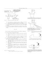
shown in Fig. 1 and Fig. 2. The algorithm flow chart for this
class of tanks is given in Fig. 3.
11.2.1 For tanks that have been stressed previously, the
examination can begin with the liquid level as high as 60 % of
the operating or maximum test level (see 8.2). Fig. 1 should be
modified for vessels that are partially full at the beginning of an
examination. The background noise baseline determination is
important for this class of examination and should be provided
5
Pentel 0.3-mm (2H) lead or its equivalent has been found satisfactory for this
purpose.
4
E1067/E1067M − 11
FIG. 1 Atmospheric Tank Examination, Stressing Sequence
FIG. 2 Vacuum Tank Examination, Stressing Sequence
11.2.3 The initial hold period is used to determine a baseline
of the background noise. This data provides an estimate of the
total background noise contribution during the examination.
Background noise shall be discounted in the final data analysis.
11.2.4 Intermittent load holds shall be for 4 min. As shown
in Fig. 4, pressure vessels shall be loaded in steps up to 30 %
of the maximum test pressure. Thereafter, the pressure shall be
for. Many vessels operate with liquid contents and partial
vacuum; however, vacuum vessels are normally examined
empty.
11.2.2 Pressure vessels that operate with superimposed
pressures greater than 0.2 MPa [30 psia] shall be loaded as
shown in Fig. 4. The algorithm flow chart for this class of tanks
is given in Fig. 5.
5
E1067/E1067M − 11
FIG. 3 AE Examination Algorithm—Flow Chart Atmospheric-Vacuum Tanks (See Fig. 1 and Fig. 2.)
FIG. 4 Pressure Tank Examination, Stressing Sequence
decreased by 10 % of the maximum test pressure before
proceeding to the next hold level. Following a decrease in
pressure, the load shall be held for 4 min before reloading.
11.2.5 For all vessels, the final load hold shall be for 30 min.
The vessel should be monitored continuously during this
period.
6
E1067/E1067M − 11
FIG. 5 AE Examination Algorithm—Flow Chart Pressure Tanks (See Fig. 4.)
12.2.2 Evaluation based on Felicity ratio is important for
in-service vessels. The Felicity ratio provides a measure of the
severity of previously induced damage. The onset of “significant” emission for determining measurement of the Felicity
ratio is a matter of experience. The following are offered as
guidelines to determine if emission is significant:
12.2.2.1 More than five bursts of emission during a 10 %
increase in load.
12.2.2.2 More than Nd/2 duration during a 10 % increase in
load, where Nd is the total duration value defined in Annex A2.
12.2.2.3 Emission continues at a load hold. For purposes of
this guideline, a short (1 min or less) nonprogrammed load
hold can be inserted in the procedure.
12.2.2.4 Felicity ratio is a condition on which acceptance
criteria may be based.
12.2.3 Evaluation based on high-amplitude events is important for new vessels. These events are often associated with
fiber breakage and are indicative of major structural damage.
This condition is less likely to govern for in-service and
previously loaded vessels where emissions during a load hold
and Felicity ratio are more important. High-amplitude events is
a condition on which acceptance criteria may be based.
12.2.4 Evaluation based on total duration is valuable for
atmospheric and vacuum tanks. Pressure vessels, particularly
on first loading, tend to be noisy and therefore evaluation for
pressure vessels is based on reloading only. Total duration is a
condition on which acceptance criteria may be based.
12.2.5 Indications located with AE should be examined by
other techniques; for example, visual, ultrasonics, dye
penetrant, etc.
11.3 Felicity Ratio Determination—The Felicity ratio is not
measured during the first loading of atmospheric tanks and
vacuum vessels. The Felicity ratio is obtained directly from the
ratio of the stress at the emission source at onset of significant
emission and the maximum prior stress at the same point.
11.3.1 The Felicity ratio is measured from the unload-reload
cycles during the first loading of pressure vessels. For subsequent loadings, the Felicity ratio is obtained directly from the
ratio of the stress at the emission source at onset of emission
and the previous maximum stress at the same point. A
secondary Felicity ratio is determined from the unload-reload
cycles.
11.4 Data Recording—Prior to an examination, the signal
propagation loss (attenuation) data, that is, amplitude as a
function of distance from the signal source, shall be recorded in
accordance with the procedure detailed in 9.3.
11.4.1 The number of hits from all channels whose amplitude exceeds the threshold setting shall be recorded. Channels
that are active during load holds should be noted.
12. Interpretation of Results
12.1 Examination Termination—The real-time instrument
displays shall be continuously monitored during the test. If any
of these displays indicate approaching failure, the vessel shall
be unloaded and the test terminated. If the inspector judges
background noise to be excessive during the test, the test shall
be terminated. “Excessive” background noise is a matter of
judgment based on experience.
12.2 Significance of Data:
12.2.1 Evaluation based on emissions during load hold is
particularly significant. Continuing emissions indicate continuing damage. Fill and other background noise will generally be
at a minimum during a load hold. Continuing emission during
hold periods is a condition on which acceptance criteria may be
based.
13. Report
13.1 The report shall include the following:
7
E1067/E1067M − 11
14. Keywords
13.1.1 Complete identification of equipment, including material type, source, method of fabrication, manufacturer’s name
and code number, date and pressure-load of previous tests, and
previous history.
13.1.2 Equipment sketch or manufacturer’s drawing with
dimensions of equipment and sensor location.
13.1.3 Test liquid employed.
13.1.4 Test liquid temperature.
13.1.5 Test Sequence—filling rate, hold times, and hold
levels.
13.1.6 Comparison of examination data with specified acceptance criteria.
13.1.7 Show on sketch or manufacturer’s drawing the location of any suspect areas found that require further evaluation.
13.1.8 Any unusual effects or observations during or prior to
the examination.
13.1.9 Dates of examination.
13.1.10 Name(s) of examiner(s).
13.1.11 Instrumentation Description—complete description
of AE instrumentation including manufacturer’s name, model
number, sensor type, system gain, serial numbers or equivalent,
software title and version number, etc.
13.1.12 Permanent Record of AE Data, for example, AE
hits versus time for zones of interest, total duration above the
threshold setting versus time, emissions during load holds, and
signal propagation loss.
14.1 felicity effect; felicity ratio; fiber debonding; fiber
pullout; resin cracking; source characterization; source location
ANNEXES
(Mandatory Information)
A1. INSTRUMENTATION PERFORMANCE REQUIREMENTS
of signal loss (typically 2 m [6 ft]) and shall be shielded against
electromagnetic interference. This requirement is omitted
where the preamplifier is mounted in the sensor housing, or a
line-driving (matched impedance) sensor is used.
A1.1 AE Sensors:
A1.1.1 General—AE sensors shall be temperature-stable
over the range of use which may be 4° to 93°C [40° to 200° F],
and shall not exhibit sensitivity changes greater than 3 dB over
this range. Sensors shall be shielded against radio frequency
and electromagnetic noise interference through proper shielding practice or differential (anticoincident) element design, or
both. Sensors shall have omnidirectional response in the plane
of contact with variations not exceeding 4 dB from the peak
response.
A1.3 Couplant—Commercially available couplants for ultrasonic flaw detection may be used. Frangible wax or quicksetting adhesives may be used, provided couplant sensitivity is
not significantly lower than with fluid couplants. Couplant
selection should be made to minimize change in coupling
sensitivity during an examination. Consideration should be
given to testing time and the surface temperature of the vessel.
A1.1.2 Sensors—Sensors shall have a resonant response
between 100 and 200 kHz. Minimum sensitivity shall be −80
dB referred to 1 volt per microbar, determined by face-to-face
ultrasonic test.
A1.4 Preamplifier—The preamplifier should be mounted in
the vicinity of the sensor, or may be in the sensor housing. If
the preamplifier is of differential design, a minimum of 40 dB
of common-mode noise rejection shall be provided. The
preamplifier bandpass shall be consistent with the frequency
range of the sensor and shall not attenuate the resonant
frequency of the sensor.
NOTE A1.1—This method measures approximate sensitivity of the
sensor. AE sensors used in the same examination should not vary in peak
sensitivity more than 3 dB from the average.
A1.2 Signal Cable—The signal cable from sensor to preamp shall not exceed a length that will cause more than 3 dB
8
E1067/E1067M − 11
A1.8 Main Processor:
A1.5 Filters—Filters shall be of the band pass type, and
shall provide a minimum of 24 dB per octave signal attenuation. Filters may be located in preamplifier or post-preamplifier
circuits, or may be integrated into the component design of the
sensor, preamplifier, or processor to limit frequency response.
Filters or integral design characteristics, or both, shall ensure
that the principal processing frequency is between 100 and 200
kHz.
A1.8.1 General—The main processor(s) shall be capable of
processing hits, peak amplitude, signal strength, and duration
on each channel.
A1.8.2 Peak-Amplitude Detection—Comparative calibration must be established in accordance with the requirements of
Annex A2. Usable dynamic range shall be a minimum of 60 dB
with 2 dB resolution. Not more than 2-dB variation in
peak-detection accuracy shall be allowed over the stated
temperature range. Amplitude values may be stated in volts or
dB, but must be referenced to a fixed gain output of the system
(sensor or preamplifier).
A1.6 Power-Signal Cable—The cable providing power to
the preamplifier and conducting the amplified signal to the
main processor shall be shielded against electromagnetic noise.
Signal loss shall be less than 1 dB/30 m [100 ft] of cable length
at 150 kHz. The recommended maximum cable length to avoid
excessive signal attenuation is 150 m [500 ft]. Digital or radio
transmission of signals is allowed consistent with practice in
transmitting those signal forms.
A1.8.3 Signal Outputs and Recording—The processor as a
minimum shall provide outputs for permanent recording of
duration, amplitude, signal strength, and hits above the threshold setting by channel (zone location) and hits. A sample
system schematic is shown in Fig. A1.1.
A1.7 Main Amplifier—The main amplifier, if used, shall
have signal response with variations not exceeding 3 dB over
the frequency range of 25 to 200 kHz, and temperature range
of 4 to 52°C [40 to 125°F]. The main amplifier shall have
adjustable gain, or an adjustable threshold for hit detection and
counting.
9
E1067/E1067M − 11
FIG. A1.1 Sample Schematic of AE Instrumentation for Vessel Testing
A2. INSTRUMENT SETTINGS
tion). The detection threshold is 12 dB lower than the average
measured amplitude of ten hits generated by a 0.3 mm [0.012
in.] Pentel pencil (2H) lead break at a distance of 610 mm [24
in.] from the sensor. All lead breaks shall be done at an angle
of approximately 30° to the surface with a 2.5 mm [0.1 in.] lead
extension. This determination may be repeated with additional
sensors, remounts as appropriate to confirm its reliability.
A2.1 General—The performance and threshold definitions
vary for different types of acoustic emission instrumentation.
Parameters such as signal strength and amplitude may vary
from manufacturer to manufacturer and from model to model
by the same manufacturer. This annex describes techniques for
generating common baseline levels for the different types of
instrumentation. Through the use of these procedures the test
sensitivity can be effectively the same regardless of instrumentation manufacturer or equipment nomenclature.
A2.3 Reference Amplitude Threshold—For large amplitude
hits, the reference amplitude threshold shall be determined
using a 300 by 5 by 2 cm [118 by 2 in. by 0.8 in.] clean, mild
steel bar. The bar shall be supported at each end on elastomeric,
or similar, isolating pads. The reference amplitude threshold is
defined as the average measured amplitude of ten hits generated by a 0.3 mm [0.012 in.] Pentel pencil (2H) lead break at
a distance of 210 cm [83 in.] from the sensor. All lead breaks
shall be done at an angle of approximately 30° to the surface
with a 2.5 mm [0.1 in.] lead extension. The sensor shall be
mounted 30 cm [12 in.] from the end of the bar on the 5 cm [2
in.] wide surface.
A2.1.1 The procedures described in A2.2 and A2.3 should
be performed at a temperature of 15 to 27°C [60 to 80°F]. It is
intended that this be a one-time determination of threshold
values for data acquisition, or evaluation, or both. For field use,
a portable acrylic rod (see Practice E2075) can be carried with
the equipment and used for periodic checking of sensor,
preamplifier, and channel sensitivity.
A2.2 Threshold of Detectability (aka Detection
Threshold)—To determine the detection threshold for AE
examinations on fiberglass vessels, a sensor of the applicable
type is mounted on one end of a 788 mm [31 in.] long, 38.1
mm [1.5 in.] diameter rod of cast acrylic material conforming
to Specification D5436. Rod setup and sensor mounting shall
be as specified in Practice E2075 (however the reference marks
specified in Practice E2075 will not be used in this applica-
A2.4 Typical Attenuation—Table A2.1 shows signal amplitude values for various distances along a cast acrylic rod of the
kind described in A2.2 and Practice E2075. These are values
for a sensor containing a piezoelectric crystal often used for
10
E1067/E1067M − 11
TABLE A2.1 Decibel Calibration Values
Distance of Pentel
Break from Sensor
100 mm [4 in.]
150 mm [6 in.]
300 mm [12 in.]
450 mm [18 in.]
600 mm [24 in.]
angle of approximately 30° to the test surface with a 2.5 mm
[0.1 in.] lead extension. Measurement points shall be chosen so
as to be representative of different constructions and thicknesses and should be performed above and below the liquid (if
applicable) and away from manways, nozzles, etc. A sensor
shall be mounted at each measurement point and two measurements shall be carried out at each location. One measurement
shall be in the principal direction of the surface fibers (if
applicable), and the second calibration shall be carried out
along a line 45° to the direction of the first measurement. Lead
breaks shall be at a distance from the measurement point so as
to provide an amplitude decibel value Am midway between the
threshold of detectability and the Reference Amplitude Threshold. The Duration Criterion at each measurement point is
defined as one hundred and thirty times the average duration
per lead break from ten 0.3 mm [0.012 in.] Pentel pencil (2H)
lead breaks at each of the two lead break locations. When
applying the Duration Criterion, the value which is representative of the region where activity is observed should be used.
Typical Decibel
Value
82.5
80.5
73.5
66.5
60.0
this kind of test. The decibel numbers in Table A2.1 are dBAE
as defined in Terminology E1316. The numbers in this table are
indicative of what may be expected when using the cast acrylic
rod in accordance with A2.2, but these numbers shall not be
taken as a substitute for performing the procedure.
A2.5 Duration Criterion ND—The Duration Criterion ND
shall be determined either before or after the examination
using a 0.3 mm [0.012 in.] Pentel pencil (2H) lead broken on
the surface of the vessel. This determination is made separately
on each vessel examined. All lead breaks shall be done at an
A3. SENSOR PLACEMENT GUIDELINES
See Figs. A3.1-A3.6.
NOTE 1—The bottom knuckle region is critical due to discontinuity stresses. Locate sensors to provide adequate coverage, for example, approximately
every 90° and 150 to 300 mm [6 to 12 in.] away from knuckle on shell.
NOTE 2—The secondary bond joint areas are suspect, for example, nozzles, manways, shell-butt joint, etc. For nozzles and manways, the preferred
sensor location is 75 to 150 mm [3 to 6 in.] from intersection with shell and below. The shell-butt joint region is important. Locate the two high-frequency
sensors up to 180° apart—one above and one below the joint.
FIG. A3.1 Case I—Atmospheric Vertical Tank
11
E1067/E1067M − 11
NOTE 1—The bottom knuckle region is critical due to discontinuity stresses. Locate sensors to provide adequate coverage, for example, approximately
every 90° and 150 to 300 mm [6 to 12 in.] away from knuckle on shell. In this example, sensors are so placed that the bottom nozzles, manways, and
baffle areas plus the knuckle region are covered.
NOTE 2—The secondary bond joint areas are suspect, for example, nozzles, manways, and baffle attachments to shell. See the last sentence of one above
for bottom region coverage in this example. Note sensor adjacent to agitator shaft-top manway. This region should be checked with agitator on.
FIG. A3.2 Case II—Atmospheric Vertical Tank
NOTE 1—The bottom head is highly stressed. Locate two sensors approximately as shown.
NOTE 2—The bottom knuckle region is critical due to discontinuity stresses. Locate sensors to provide adequate coverage, for example, approximately
every 90° and 150 to 300 mm [6 to 12 in.] away from knuckle on shell. The top knuckle region is similarly treated.
NOTE 3—The secondary bond areas are suspect, that is, nozzles, manways, and leg attachments. For nozzles and manways, the preferred sensor location
is 75 to 150 mm [3 to 6 in.] from the intersection with shell and below. For leg attachments, therefore should be a sensor within 300 mm [12 in.] of the
shell-leg interface.
FIG. A3.3 Case III—Atmospheric-Pressure Vessel Tank
12
E1067/E1067M − 11
NOTE 1—The secondary bond-joint areas are suspect, that is, nozzles, manways, and body flanges. Particularly critical in this tank are the bottom
manway and nozzle. For nozzles and manways, the preferred sensor location is 75 to 150 mm [3 to 6 in.] from intersection with shell and below. The
bottom flange in this example is covered by a sensor 75 to 150 mm [3 to 6 in.] above the manway.
NOTE 2—The knuckle regions are suspect due to discontinuity stresses. Locate sensors to provide adequate coverage, that is, approximately every 90°
and 75 to 150 mm [6 to 12 in.] away from knuckle on shell.
FIG. A3.4 Case IV—Atmospheric-Pressure Vertical Tank
NOTE 1—The knuckle regions are suspect due to discontinuity stresses. Locate sensors to provide adequate coverage, that is, approximately every 90°
and 150 to 300 mm [6 to 12 in.] away from knuckle on shell.
NOTE 2—The secondary bond-joint areas are critical, for example, nozzles, manways, and shell-butt joint. For nozzles and manways, the preferred
sensor location is 75 to 150 mm [3 to 6 in.] from the intersection with the shell (or head) and below, where possible. The shell butt joint region is
important. Locate sensors up to 180° apart where possible and alternately above and below joint.
FIG. A3.5 Case V—Atmospheric-Vacuum Vertical Tank
13
E1067/E1067M − 11
NOTE 1—The discontinuity stresses at the intersection of the heads and the shell in the bottom region are important. Sensors should be located to detect
structural problems in these areas.
NOTE 2—The secondary bond-joint areas are suspect, for example, shell-butt joint, nozzles, manways, and sump. The preferred sensor location is 75
to 150 mm [3 to 6 in.] from intersecting surfaces of revolution. The shell butt-joint region is important. Locate the two high-frequency sensors up to 180°
apart—one on either side of the joint.
FIG. A3.6 Case VI—Atmospheric-Pressure Horizontal Tank
APPENDIX
(Nonmandatory Information)
X1. RATIONALE
X1.1 This practice was rewritten from the “Recommended
Practice for Acoustic Emission Testing of Fiberglass Tanks/
Vessels,” which was developed by the Committee on Acoustic
Emission from Reinforced Plastics (CARP) and published by
the Reinforced/Composites Institute of the Society of the
Plastics Industry (SPI).
X1.3 Criteria for evaluating the condition of FRP tanks and
the need for secondary inspection were established while
working with AE equipment, characteristics, and setup conditions listed in Table X1.1.
X1.4 Acceptance criteria are found in Table X1.2.
X1.2 The CARP Recommended Practice has been used
successfully on numerous applications.
14
E1067/E1067M − 11
TABLE X1.1 Acoustic Emission Equipment, Characteristics, and
Setup Conditions
Sensors
−77 dBV ref. 1V/ubar, at
approximately 150 kHz
silicone grease
40 dB (X100)
100 to 300 kHz bandpass
<150 m [500 ft]
46 dBAE
76 dBAE
100 to 300 kHz bandpass
10 ms
<40 dBAE
>80 dBAE
Couplant
Preamplifier gain
Preamplifier filter
Power/signal cable length
Low-amplitude threshold
High-amplitude threshold
Signal processor filter
Dead time
Background noise
Sensitivity check
TABLE X1.2 Acceptance Criteria
NOTE 1—An acceptable vessel must meet all of the following criteria. Underlined criteria carry the greatest weight. Background noise must be properly
discounted when applying acceptance criteria.
Tanks (internal pressure no greater than 0.1 MPa
absolute [14.5 psia] above the static pressure
due to internal contents, or vacuum with differential pressure no greater than 0.1 MPa [14.5 psi])
First Filling
Pressure Vessels (internal pressure no greater
than 1.73 MPa absolute [250 psia] above the
static pressure due to internal contents)A
Significance of Criterion
Subsequent Fillings
Subsequent Loadings
Emissions during hold
No hits having an
amplitude greater
than Am beyond 2
minB
None beyond 2 min
None beyond 2 min
Measure of continuing
permanent damageC
Felicity ratio
Not applicable
Greater than 0.95
Greater than 0.95
Measure of severity of
previously induced
damage
Cumulative Duration,
NDD
Less than ND
Less than ND/2
High amplitude hits
Less than 5
None
Less than ND/2
Measure of overall damage during a load
cycle
Less than 5
Measure of high energy
microstructural failures. This criterion is
often associated with
fiber breakage.
A
Above the static pressure due to the internal contents.
Decibel value Am as defined in A2.5.
C
Permanent damage may include microcracking, debonding, and fiber pull-out.
D
Varies with instrumentation manufacturer. See A2.5 for functional definition of ND.
B
SUMMARY OF CHANGES
Committee E07 has identified the location of selected changes to this standard since the last issue (E1067 - 07)
that may impact the use of this standard. (July 1, 2011)
(6) Deleted 9.5.1.2 and 10.1.2 since all current AE instruments
have amplitude analysis.
(7) Deleted 9.5.1.3 since high and low amplitude thresholds are
no longer specified.
(8) Deleted parts of 11.4.1 that specified counts and low and
high amplitude thresholds and low and high frequency channels.
(9) Rewrote 12.1 which describes examination termination
using current AE instruments.
(10) Removed high and low amplitude thresholds in old
subsection 13.1.12.
(1) Changed 1.5 to reflect the change to a combined standard.
(2) Added Practice E2075 as a reference in 2.1.
(3) Removed count value Nc, high amplitude threshold, and
low amplitude threshold from Section 3 and renumbered
subsequent subsections appropriately.
(4) Updated instrument requirements in Section 7 in terms
more current with AE instruments, as noted in changes of 7.2,
and added 7.4, 7.5, and 7.6.
(5) Removed the need for “High Frequency Sensors” and
“Low Frequency Sensors” from Section 9, subsections 9.3 and
9.4 and elsewhere in the document.
15
E1067/E1067M − 11
(19) Each section in Annex A2 has been replaced with a new
paragraph reflecting the use of current AE instruments, the new
procedure that eliminates a hazardous lead sheet to establish
common baseline levels, and the new examination procedure
based on duration criterion.
(20) An attenuation versus distance reference table has been
added as Table A2.1.
(21) Note 3 has been removed from Fig. A3.1, Fig. A3.2, Fig.
A3.5, and Fig. A3.6.
(22) Note 4 has been removed from Fig. A3.3,
(23) The last sentence in Note 1 of Fig. A3.4 has been
removed.
(11) Removed High Frequency sensor reference in A1.1.2.
(12) Removed subsection A1.1.3 to remove Low Frequency
sensors from the standard.
(13) Removed low and high frequency sensor discussion from
A1.5.
(14) Removed parts of the A1.8.1 dealing with low and high
frequency channels.
(15) Removed subsection A1.8.1.1 since this is not used in
current AE instrumentation.
(16) Removed subsection A1.8.1.2 as low and high frequency
channels are used in this examination.
(17) Modified paragraph to reflect the use of current day AE
instruments.
(18) Replaced Fig. A1.1 with current AE system block diagram.
ASTM International takes no position respecting the validity of any patent rights asserted in connection with any item mentioned
in this standard. Users of this standard are expressly advised that determination of the validity of any such patent rights, and the risk
of infringement of such rights, are entirely their own responsibility.
This standard is subject to revision at any time by the responsible technical committee and must be reviewed every five years and
if not revised, either reapproved or withdrawn. Your comments are invited either for revision of this standard or for additional standards
and should be addressed to ASTM International Headquarters. Your comments will receive careful consideration at a meeting of the
responsible technical committee, which you may attend. If you feel that your comments have not received a fair hearing you should
make your views known to the ASTM Committee on Standards, at the address shown below.
This standard is copyrighted by ASTM International, 100 Barr Harbor Drive, PO Box C700, West Conshohocken, PA 19428-2959,
United States. Individual reprints (single or multiple copies) of this standard may be obtained by contacting ASTM at the above
address or at 610-832-9585 (phone), 610-832-9555 (fax), or (e-mail); or through the ASTM website
(www.astm.org). Permission rights to photocopy the standard may also be secured from the Copyright Clearance Center, 222
Rosewood Drive, Danvers, MA 01923, Tel: (978) 646-2600; />
16