Astm e 1375 90 (2002)
Bạn đang xem bản rút gọn của tài liệu. Xem và tải ngay bản đầy đủ của tài liệu tại đây (65.36 KB, 6 trang )
Designation: E 1375 – 90 (Reapproved 2002)
Standard Test Method for
Measuring the Interzone Attenuation of Furniture Panels
Used as Acoustical Barriers1
This standard is issued under the fixed designation E 1375; the number immediately following the designation indicates the year of
original adoption or, in the case of revision, the year of last revision. A number in parentheses indicates the year of last reapproval. A
superscript epsilon (e) indicates an editorial change since the last revision or reapproval.
INTRODUCTION
This test method is one of a series for the measurement and evaluation of acoustical components
affecting speech privacy in open-plan spaces. This test method provides a means of objectively
measuring the relevant acoustical characteristics of one component of the open-plan space, furniture
panels used as acoustical barriers.
C 423 Test Method for Sound Absorption and Sound Absorption Coefficients by the Reverberation Room Method3
C 634 Terminology Relating to Environmental Acoustics3
E 795 Practices for Mounting Test Specimens During
Sound Absorption Tests3
E 1110 Classification for Determination of Articulation
Class3
E 1130 Test Method for Objective Measurement of Speech
Privacy in Open Offices Using Articulation Index3
E 1179 Specification for Sound Sources Used for Testing
Open Office Components and Systems3
2.2 ANSI Standards:
S1.4 Specification for Sound Level Meters4
S1.6 Preferred Frequencies and Band Numbers for Acoustical Measurements4
S1.11 Specification for Octave Band and Fractional-Octave
Band Analog and Digital Filters4
S1.12 Specification for Laboratory Standard Microphones4
1. Scope
1.1 This test method covers the measurement of the interzone attenuation of furniture panels used as acoustical barriers
in open-plan spaces to provide speech privacy or sound
isolation between working positions.2
1.2 This test procedure was originally developed using the
foot-pound system of units for prescribing measurement positions and distances. However, the use of SI units is preferred by
ASTM. For this reason, dimensions are provided in SI units,
with approximate foot-pound conversions indicated.
1.2.1 Unless otherwise qualified, all dimensions specified in
this test method shall be understood to have a tolerance of 625
mm (61 in.), even though the indicated approximate conversions of the numerical dimensions given will not always be
accurate to this extent. All measurements shall be made in SI
units or the corresponding exact foot-pound units.
1.3 This standard does not purport to address all of the
safety concerns, if any, associated with its use. It is the
responsibility of the user of this standard to establish appropriate safety and health practices and determine the applicability of regulatory limitations prior to use.
3. Terminology
3.1 Definitions—For definition of terms used in this test
method see Terminology C 634. The term source point is
defined in Specification E 1179.
3.2 Definitions of Terms Specific to This Standard:
3.2.1 furniture panel—a furnishing that does not extend to
the ceiling, and that is used to subdivide an open-plan space
and provide some degree of visual and acoustical privacy.
Furniture panels include interlocking systems furniture and
freestanding screens.
2. Referenced Documents
2.1 ASTM Standards:
1
This test method is under the jurisdiction of ASTM Committee E33 on
Environmental Acoustics and is the direct responsibility of Subcommittee E33.02 on
Open Plan Spaces.
Current edition approved July 27, 1990. Published September 1990.
2
This test method is similar to a procedure developed by the United States
Government General Services Administration, Public Buildings Service, designated
“PBS-C.2, Test Method for the Sufficient Verification of Speech Privacy Potential
Based on Objective Measurements including Methods for the Rating of Functional
Interzone Attenuation and NC-Background, August 1972.”
3
Annual Book of ASTM Standards, Vol 04.06.
Available from American National Standards Institute, 25 W. 43rd St., 4th
Floor, New York, NY 10036.
4
Copyright © ASTM International, 100 Barr Harbor Drive, PO Box C700, West Conshohocken, PA 19428-2959, United States.
1
E 1375
walls, can significantly lower the degree of speech privacy or
noise isolation afforded between workstations. The degree of
speech privacy or noise isolation depends upon many factors.
In travelling from one workstation to another, sound may be
reflected from the ceiling system, may be diffracted over or
around intervening furniture panels that act as acoustical
barriers, may be transmitted through the furniture panels, or
may be reflected around the panel by furniture or fixed
constructions, such as walls or columns. Providing adequate
speech privacy in open-plan spaces requires the use of an
acoustically absorbent ceiling and often the use of controlled
background masking sound, in addition to partial height
acoustical barriers.
5.2 This test method measures one of the relevant acoustical
properties of one component of the open office environment:
the effectiveness of furniture panels as acoustical barriers. The
method measures the degree to which sound is diffracted over
the top edge and transmitted through the panel. Other test
methods deal with the evaluation of the degree to which
reflected sound is attenuated by open-plan components, such as
the ceiling system, furniture panels, and wall finishes. Test
Method E 1130 is available to evaluate the overall speech
privacy between workstations that results from a specific
configuration of components.
3.2.2 interzone attenuation—at a specified position, for a
one-third octave-band, the difference between the sound pressure level at a nominal reference position 0.9 m (3 ft) from the
sound source and the sound pressure level at the point in
question.
3.2.3 nominal interzone attenuation—for a one-third
octave-band, at a specified point, the arithmetic mean interzone
attenuation calculated using the interzone attenuation for the
point in question and for two adjacent positions 0.3 m (1 ft) to
either side. (See Figs. 1 and 2.) For example, in Fig. 1, the
nominal interzone attenuation at the 3.0-m (10-ft) position is
the arithmetic mean of the interzone attenuations at the 2.7, 3.0,
and 3.3-m (9, 10, and 11-ft) positions.
4. Summary of Test Method
4.1 The test facility is a room constructed such that sound
reflections from the walls and ceiling are negligible. The test
specimen is a furniture panel arranged as an acoustical barrier,
that is, arranged such that it blocks the direct path of sound
from the sound source to the measuring microphones. Sound
generated by the sound source on one side of the furniture
panel under test reaches the other side chiefly by diffracting
over its top edge. A potential secondary path is transmission
through the panel. The differences in sound pressure levels
measured on each side of the furniture panel provide a measure
of its effectiveness as an acoustical barrier.
6. Apparatus
5. Significance and Use
5.1 In open plan spaces, furniture panels are often used in
lieu of full height walls to visually and acoustically separate
workstations. The use of these units, compared to full-height
6.1 A sound source meeting Specification E 1179 is required.
6.2 Microphones shall meet the requirements in ANSI
S1.12.
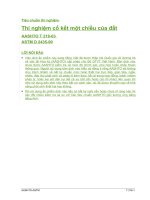
NOTE 1—See Fig. 2 for near survey line measurement positions.
NOTE 2—See Fig. 3 for measurement positions for reference levels.
FIG. 1 Plan of Test Arrangement
2
E 1375
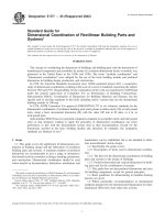
FIG. 2 Plan of Test Arrangement Showing Near Survey Path Positions
7.5 The dimensions of the facility will limit the size of
specimens that can be tested. The required minimum set of
plan-view room dimensions is 4 by 6 m (13 by 20 ft) measured
to the inner face of the absorptive coverings. The height of the
facility, measured from the floor to the inner face of the
sound-absorptive covering on the ceiling, shall be 2.7 m (9 ft).
6.2.1 The microphones shall satisfy the requirements of
11.1.
6.3 Electronic instruments used to process the microphone
signals shall conform to the relevant sections of ANSI S1.4 and
shall meet Type 1 requirements.
7. Test Facility
7.1 The preferred test facility is a hemi-anechoic room, a
room with negligible reflections from the walls and ceilings, in
the frequency range of the measurements. A room meeting the
requirements of 7.2 is satisfactory. The floor shall be made
from a hard, sound-reflective material, such as concrete or
wood, covered with carpet as specified in 7.3.
7.2 The wall and ceiling coverings shall have random
incidence sound absorption coefficients of at least 0.95 at all
frequencies at which measurements are to be made.
NOTE 2—The facility may be intended for use with other test procedures whose requirements may be more or less stringent than these. These
standards should be consulted so that for newly engineered facilities, an
optimum design is achieved.
8. Test Specimens
8.1 Furniture panels to be tested shall be assembled in
accordance with the manufacturer’s instructions and shall be
arranged as they would normally be arranged in an open office.
Joints between panels shall be sealed by no other means than
those provided or recommended by the manufacturer.
8.2 In order to prevent flanking around the ends of a panel,
the width of the specimen shall be at least twice its height or its
width may be the same as the width of the test facility. Two or
more panels may be placed or joined edge to edge to meet these
recommendations. Normal installation procedure shall be followed.
8.3 The height of the specimen should not exceed 2.4 m (8
ft). If the specimen is higher than 2.4 m (8 ft), the height shall
be completely documented in the test report as discussed in
13.2.1.
8.4 Furniture panels may be tested with accessories attached
to them. The accessories and the positions where they are
attached shall be fully described in the test report.
8.5 Furniture panels that are significantly asymmetrical,
such as curved screens, shall be tested twice, once with each
NOTE 1—Since reflections from the walls and ceiling of the facility may
reduce the measured attenuations, it is important to eliminate these
reflections as much as possible.
7.2.1 The random incidence sound absorption coefficients of
the wall and ceiling coverings shall be measured following Test
Method C 423 and Practices E 795. The mounting used shall
be those that will be used in the actual test facility.
7.3 The floor shall be of solid material such as concrete or
plywood. It shall be covered with carpet, without underpad,
typical of those used in open-plan spaces. The carpet shall have
a noise reduction coefficient (NRC) in the range of 0.20 to 0.40
when measured in a Type A mounting (see Practices E 795)
according to Test Method C 423. The carpet may be installed
and tested using tape or adhesive in the mounting.
7.4 The ceiling of the test facility should be at least 0.3 m (1
ft) from the edge of the test specimen. (See also 7.5 and 8.3.)
3
E 1375
face toward the sound source. The test results for each
orientation shall be reported separately.
9. Test Signal
9.1 Signal Spectrum—The electrical signals used to generate the sound signals used for this test shall form a series of
bands of random noise containing an essentially continuous
distribution of frequencies over each test band.
9.1.1 The generated sound shall be adequate to maintain, at
each of the desired measurement locations, one-third octaveband sound pressure levels at least 10 dB above the background noise levels of the test facility and the measuring
instrumentation.
9.2 Bandwidth—The measurement bandwidth shall be onethird octave. Specifically, the overall frequency response of the
electrical system, including the filter or filters in the source or
sound measurement sections, shall for each test band meet the
requirements of ANSI S1.11 for one third octave band filters of
Order 3 or higher, Type 1 or better.
9.2.1 Filters in the sound measurement system serve to filter
out extraneous noise lying outside the test bands, including
possible distortion produced in the source system.
9.3 Standard Test Frequencies—The minimum range of
measurements shall be a series of contiguous one-third octave
bands with center frequencies from 200 to 5000 Hz conforming
to ANSI S1.6. If desired, the range may be extended provided
that the requirements of 7.1 and 7.2 are met.
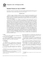
FIG. 3 Measurement Positions for Reference Levels
voltmeters by removing the microphone and driving them directly with an
electrical signal. (Consult instruction manual for applicability.)
10.1.3 Measurements With the Test Specimen: Standard
Survey Path (see Fig. 1):
10.1.3.1 Position the sound source so that the loudspeaker
axis is parallel the floor and 1.2 m (4 ft) above it with the
source point 1.8 m (6 ft) from the centerline of the specimen.
In plan view, center the loudspeaker axis on the specimen (see
Fig. 1).
10.1.3.2 Make measurements on the side of the panel away
from the sound source on the loudspeaker axis at distances of
2.1, 2.4, 2.7, 3.0, 3.3, 3.6, 3.9, and 4.2 m (7, 8, 9, 10, 11, 12,
13 and 14 ft) from the source point (see Fig. 1). Additional
measurements may be made at greater or smaller distances, as
desired.
10.1.3.3 Make all measurements with the microphone or
microphones positioned 1.2 m (4 ft) above the floor.
10.1.4 Measurements With Test Specimen: Near Survey
Path—(see Fig. 2):
10.1.4.1 Additional measurements are made as described in
10.1.4.2-10.1.4.5 to assess the direct transmission of sound
through the specimen or through specimen joints. These
additional measurements are made at positions on the near
survey line parallel to the specimen and 0.3 m (1 ft) from the
specimen on the side away from the sound source (see Fig. 2).
10.1.4.2 Leave the sound source positioned at the same
location and with the same orientation as in 10.1.3.1.
10.1.4.3 Make measurements near the plan-view center of
the specimen (if the specimen consists of a single furniture
panel) or near the plan-view center of the panel closest to the
specimen center line (if the specimen consists of panels joined
as in 8.2). Make measurements at three positions along the near
survey line, including a position directly opposite the panel
center and at positions 0.3 m (1 ft) to either side of this position
(see Fig. 2).
10.1.4.4 If the specimen consists of two or more furniture
panels joined as in 8.2, make measurements near the joint
closest to the plan-view centerline of the specimen. Make
measurements at three positions along the near survey path; at
a position directly opposite the joint, and at positions 0.3 m (1
ft) to either side of this position (see Fig. 2).
10.1.4.5 Make all measurements with the microphone or
microphones positioned 1.2 m (4 ft) above the floor.
10. Procedure
10.1 Measurement of Sound Pressure Levels:
10.1.1 Orient microphones so that for each frequency band
they have a uniform directional response within 61 dB in the
plane that is perpendicular to the floor and that passes through
the source point and the microphone. A vertical orientation of
the microphone axis is preferred. (Measure the directional
responses of the microphones under laboratory-empty conditions, not with the specimen in place, or take them from the
manufacturer’s literature.)
10.1.1.1 Individually calibrate multiple microphones where
they are used and make corrections for differences in sensitivity during the calculations.
10.1.2 Measurement of Reference Levels:
10.1.2.1 Position the sound source so that the loudspeaker
axis is parallel to the floor and 1.2 m (4 ft) above it.
10.1.2.2 The reference sound pressure level in each onethird octave-band is the arithmetic average of the levels on the
loudspeaker axis at 0.6, 0.9, and 1.2-m (2, 3, and 4 ft) from the
source point (see Fig. 3). Obtain these levels with no specimen
or hard surface present in the test facility and with the carpet
exposed. Alternatively, these reference values may be obtained
with the source moved away from the specimen and the walls
provided that any sound reflecting surfaces are covered with
sound absorptive material.
10.1.2.3 Measure the electrical signal fed to the source and
maintain it at the same level during the measurement of the
sound transmitted beyond the test specimen. This may be
accomplished by measuring the voltage fed to the loudspeaker.
NOTE 3—Some precision sound level meters may be used as wide-band
4
E 1375
13.2.1 Report the clearance between the top of the specimen
and the absorptive covering of the test facility ceiling where the
clearance is less than that recommended in 7.4.
13.3 Tabulate the measured interzone attenuations calculated in 11.1 to the nearest 1 dB for all positions and
frequencies examined.
13.4 Report the nominal interzone attenuations calculated in
11.2 and 11.3, and the articulation class values calculated in
12.1.
13.5 Where both faces of a specimen are tested as in 8.5, the
measured interzone attenuations, nominal interzone attenuations, and articulation class values shall be reported for each
orientation separately.
11. Calculation
11.1 Determine the interzone attenuation for each receiving
position in each one-third octave band by calculating the
difference, rounded to the nearest decibel, between the reference sound pressure level and the level measured at the
receiving position.
11.2 Calculate the nominal interzone attenuations along the
standard survey path for each of the 2.4, 2.7, 3.0, 3.3, 3.6, and
3.9-m (8, 9, 10, 11, 12, and 13-ft) positions.
11.3 Calculate the nominal interzone attenuations along the
near survey path as follows. Calculate the nominal interzone
attenuations for the panel-center position by averaging the
values obtained at the three positions described in 10.1.4.3. If
measurements were made as described in 10.1.4.4, calculate
the nominal interzone attenuation for the panel-joint position
by averaging the values obtained at the three positions described in 10.1.4.4.
14. Precision and Bias
14.1 The precision associated with the measurement of
sound pressure levels depends on the interpretation of the
output of the instrumentation used; for example, sound level
meter, level recorder, or digital analyzer.
14.2 The bias of level measurements and differences is
determined by the bias of all the associated instrumentation.
Any inaccuracies in this area should be made negligible by
careful calibration.
14.3 The precision of this test method should be determined
annually by performing several tests on a single specimen. The
test specimen should be removed and reinstalled after each test.
In a laboratory routinely carrying out tests under this test
method, such precision checks should be carried out within 6
months of any tests.
14.4 Studies are planned to evaluate the reproducibility of
this test method.
12. Single Number Classification
12.1 The articulation class (AC) shall be calculated according to Classification E 1110 for the 2.4, 2.7, 3.0, 3.3, 3.6, and
3.9-m (8, 9, 10, 11, 12, and 13-ft) nominal interzone attenuations. The articulation class shall also be calculated for the
panel-center and (if measured) panel-joint positions. The
articulation class values shall be reported for all of these
positions, with the positions clearly identified. The minimum
of these AC values may be reported as the “minimum articulation class,” without a qualifying distance or location.
13. Report
13.1 The report shall include a statement, if true in every
respect, that the tests were conducted in accordance with the
provisions of this test method. Any deviations from this test
method shall be fully reported.
13.2 A complete description of the assembly under test shall
be given, including all of the essential construction and
dimensions. If this description has not been determined by
direct examination, the test report shall so indicate.
15. Keywords
15.1 acoustical barrier; acoustical component; architectural
acoustics; component test; furniture panel; interzone attenuation; open office; open office component; open-plan space;
speech privacy
ANNEX
(Mandatory Information)
A1. GUIDE FOR ACCREDITATION OF TESTING LABORATORIES
A1.1 Scope
A1.1.1 This annex provides guidelines for agencies evaluating testing laboratories for the purpose of granting accreditation for this test method.
E 548 Guide for General Criteria Used for Evaluating
Laboratory Competence5
A1.2 Referenced Documents
A1.2.1 ASTM Standards:
C 634 Terminology Relating to Environmental Acoustics3
5
5
Annual Book of ASTM Standards, Vol 14.02.
E 1375
A1.3 Terminology
A1.8 Requirements for Analysis and Measurement
A1.8.1 The laboratory shall have evidence that the microphones used meet the requirements of 6.2 and 10.1.
A1.8.2 The laboratory shall have evidence that the instruments meet the requirements of 6.3.
A1.8.3 The laboratories shall have evidence that the filters
used meet the requirements of 9.2.
A1.8.4 The laboratory shall produce test data to show that
background noise levels for the facility will meet the requirements of 9.1.1.
A1.3.1 Descriptions of Terms Specific to This Annex—The
acoustical terminology used in this annex is consistent with
Terminology C 634 and Practice E 548.
A1.4 Organization of the Agency
A1.4.1 A description of the organization shall be given
following the requirements of Practice E 548.
A1.5 Human Resources of the Agency
A1.9 Precision and Bias
A1.9.1 Calibration records shall be produced to demonstrate
compliance with 14.2.
A1.9.2 The data obtained from the procedure in 14.3 shall
be produced to demonstrate that the requirements of 14.3 are
satisfied.
A1.5.1 A description of the agency personnel responsible
for testing shall be supplied following the requirements of
Practice E 548.
A1.6 Facility Requirements
A1.6.1 The laboratory shall produce test data demonstrating
compliance with the requirements of 7.2, 7.2.1, 7.3, and 7.5.
A1.10 General
A1.10.1 Instruments, techniques, and individual capabilities
may vary between testing laboratories. The accrediting agency
should ensure that its accrediting personnel are competent to
deal with and correctly evaluate unusual instruments or
techniques.
A1.7 Source Requirements
A1.7.1 The laboratory shall produce test data demonstrating
compliance with 6.1.
ASTM International takes no position respecting the validity of any patent rights asserted in connection with any item mentioned
in this standard. Users of this standard are expressly advised that determination of the validity of any such patent rights, and the risk
of infringement of such rights, are entirely their own responsibility.
This standard is subject to revision at any time by the responsible technical committee and must be reviewed every five years and
if not revised, either reapproved or withdrawn. Your comments are invited either for revision of this standard or for additional standards
and should be addressed to ASTM International Headquarters. Your comments will receive careful consideration at a meeting of the
responsible technical committee, which you may attend. If you feel that your comments have not received a fair hearing you should
make your views known to the ASTM Committee on Standards, at the address shown below.
This standard is copyrighted by ASTM International, 100 Barr Harbor Drive, PO Box C700, West Conshohocken, PA 19428-2959,
United States. Individual reprints (single or multiple copies) of this standard may be obtained by contacting ASTM at the above
address or at 610-832-9585 (phone), 610-832-9555 (fax), or (e-mail); or through the ASTM website
(www.astm.org).
6