Astm e 1417 e 1417m 16
Bạn đang xem bản rút gọn của tài liệu. Xem và tải ngay bản đầy đủ của tài liệu tại đây (187.15 KB, 11 trang )
Designation: E1417/E1417M − 16
Standard Practice for
Liquid Penetrant Testing1
This standard is issued under the fixed designation E1417/E1417M; the number immediately following the designation indicates the year
of original adoption or, in the case of revision, the year of last revision. A number in parentheses indicates the year of last reapproval.
A superscript epsilon (´) indicates an editorial change since the last revision or reapproval.
This standard has been approved for use by agencies of the U.S. Department of Defense.
priate safety and health practices and determine the applicability of regulatory limitations prior to use.
1. Scope*
1.1 This practice establishes the minimum requirements for
conducting liquid penetrant examination of nonporous metal,
and nonmetal components.
2. Referenced Documents
2.1 The following documents form a part of this practice to
the extent specified herein:
NOTE 1—This practice replaces MIL-STD-6866.
1.2 The penetrant examination processes described in this
practice are applicable to in-process, final, and maintenance
(in-service) examinations. These processes are applicable for
the detection of discontinuities, such as lack of fusion,
corrosion, cracks, laps, cold shuts, and porosity, that are open
or connected to the surface of the component under examination.
2.2 ASTM Standards:2
D95 Test Method for Water in Petroleum Products and
Bituminous Materials by Distillation
D2512 Test Method for Compatibility of Materials with
Liquid Oxygen (Impact Sensitivity Threshold and PassFail Techniques)
D6304 Test Method for Determination of Water in Petroleum Products, Lubricating Oils, and Additives by Coulometric Karl Fischer Titration
E165 Practice for Liquid Penetrant Examination for General
Industry
E543 Specification for Agencies Performing Nondestructive
Testing
E1135 Test Method for Comparing the Brightness of Fluorescent Penetrants
E1316 Terminology for Nondestructive Examinations
E2297 Guide for Use of UV-A and Visible Light Sources and
Meters used in the Liquid Penetrant and Magnetic Particle
Methods
E3022 Practice for Measurement of Emission Characteristics and Requirements for LED UV-A Lamps Used in
Fluorescent Penetrant and Magnetic Particle Testing
2.3 ASNT Standards:3
ANSI/ASNT-CP-189 Standard for Qualification and Certification of Nondestructive Testing Personnel
SNT-TC-1A Recommended Practice for Personnel Qualification and Certification in Nondestructive Testing
1.3 Caution must be exercised in the usage of elevated
temperature with components manufactured from thermoplastic materials. Also, some cleaners, penetrants, and developers
can have a deleterious effect on nonmetallic materials such as
plastics. Prior to examination, tests should be conducted to
ensure that none of the cleaning or examination materials are
harmful to the components to be examined.
1.4 Units—The values stated in either SI units or inchpound units are to be regarded separately as standard. The
values stated in each system may not be exact equivalents;
therefore, each system shall be used independently of the other.
Combining values from the two systems may result in nonconformance with the standard.
1.5 All areas of this practice may be open to agreement
between the cognizant engineering organization and the
supplier, or specific direction from the cognizant engineering
organization.
1.6 This standard does not purport to address all of the
safety concerns, if any, associated with its use. It is the
responsibility of the user of this standard to establish appro1
This practice is under the jurisdiction of ASTM Committee E07 on Nondestructive Testing and is the direct responsibility of Subcommittee E07.03 on Liquid
Penetrant and Magnetic Particle Methods.
Current edition approved June 15, 2016. Published July 2016. Originally
approved in 1991. Last previous edition approved in 2013 as E1417/E1417M – 13.
DOI: 10.1520/E1417_E1417M-16.
2
For referenced ASTM standards, visit the ASTM website, www.astm.org, or
contact ASTM Customer Service at For Annual Book of ASTM
Standards volume information, refer to the standard’s Document Summary page on
the ASTM website.
3
Available from American Society for Nondestructive Testing (ASNT), P.O. Box
28518, 1711 Arlingate Ln., Columbus, OH 43228-0518, .
*A Summary of Changes section appears at the end of this standard
Copyright © ASTM International, 100 Barr Harbor Drive, PO Box C700, West Conshohocken, PA 19428-2959. United States
1
E1417/E1417M − 16
2.4 Military Standards:4, 5
MIL-STD-792 Identification Marking Requirements for
Special Purpose Components
QPL-AMS-2644 Qualified Products List, Inspection
Material, Penetrant
MIL-STD-45662 Calibration System Requirements
2.5 ANSI/ISO/AIA Standards:6
ANSI/NCSL Z540-1 General Requirement for Calibration
Laboratories and Measuring Test Equipment
ISO 10012 Measurement
Management
Systems—
Requirements for Measuring Measurement Process and
Measuring Equipment
NAS 410 Certification and Qualification of Nondestructive
Test Personnel
2.6 SAE Standard:7
AMS 2644 Inspection Material, Penetrant
AMS 2175A Castings, Classification and Inspection of
2.7 DoD Contracts—Unless otherwise specified, the issues
of the documents that are DoD adopted are those listed in the
issue of the DoDISS (Department of Defense Index of Specifications and Standards) cited in the solicitation.
3.2.6 in-service—refers to components that are in use or
storage for their intended function.
3.2.7 linear indication—penetrant indications with at least a
three to one length to width ratio.
3.2.8 reprocess—repeat, after cleaning, the application and
appropriate processing of penetrant, emulsifier (as required),
and developer (as required).
3.2.9 rounded indication—penetrant indication whose
length to width ratio is less than three-to-one.
3.2.10 supplier—the organization contracted to supply the
material, parts, or assembly.
3.2.11 turbine engine critical components—any component
on turbine engine designated by the manufacturer as “critical.”
4. Significance and Use
4.1 This practice establishes the basic parameters for controlling the application of the liquid penetrant method. This
practice is written so it can be specified on the engineering
drawing, specification, or contract. It is not a detailed how-to
procedure to be used by the inspector and, therefore, must be
supplemented by a detailed procedure that conforms to the
requirements of this practice. Specification E165 contains
information to help develop detailed requirements.
2.8 Order of Precedence—In the event of conflict between
the text of this practice and the references cited herein, the text
of this practice takes precedence.
5. Classification
5.1 Penetrant examination processes and materials are classified in accordance with the material classification contained
in AMS 2644. Penetrant systems covered by this practice shall
be of the following types, methods, and sensitivity levels:
5.1.1 Type:
5.1.1.1 Type I—Fluorescent dye.
5.1.1.2 Type II—Visible dye.
5.1.2 Method:
5.1.2.1 Method A—Water washable.
5.1.2.2 Method B—Post-emulsifiable, lipophilic.
5.1.2.3 Method C—Solvent-removable.
5.1.2.4 Method D—Post-emulsifiable, hydrophilic.
5.1.3 Sensitivity—(These levels apply to Type I penetrant
systems only. Type II penetrant systems have only a single
sensitivity and it is not represented by any of the levels listed
as follows):
5.1.3.1 Sensitivity Level 1⁄2 —Very low.
5.1.3.2 Sensitivity Level 1—Low.
5.1.3.3 Sensitivity Level 2—Medium.
5.1.3.4 Sensitivity Level 3—High.
5.1.3.5 Sensitivity Level 4—Ultrahigh.
3. Terminology
3.1 Definitions:
3.1.1 The terminology relating to liquid penetrant examination that appears in Terminology E1316 shall apply to the terms
used in this practice.
3.2 Definitions of Terms Specific to This Standard:
3.2.1 aerospace—any component that will be installed on a
system that flies.
3.2.2 cognizant engineering organization (CEO)—
Reference Terminology Standard E1316.
3.2.3 component—the part(s) or element(s) of a system
described, assembled, or processed to the extent specified by
the drawing.
3.2.4 final examination—the final examination performed
for the acceptance of the item. Any change to the item’s surface
such as machining, grinding, welding, heat treatment, or
etching by subsequent manufacturing operation, may render
the previous examination invalid, requiring reexamination of
all affected surfaces, unless otherwise approved in the contract.
3.2.5 in-process—that which occurs during manufacturing
before a component is in final form.
5.2 Developers shall be of the following forms:
5.2.1 Form a—Dry powder.
5.2.2 Form b—Water-soluble.
5.2.3 Form c—Water-suspendable.
5.2.4 Form d—Nonaqueous for Type I fluorescent penetrant.
5.2.5 Form e—Nonaqueous for Type II visible dye.
5.2.6 Form f—Specific application.
4
Copies of specifications, standards, drawings, and publications required by
manufacturers in connection with specific acquisition functions should be obtained
from the contracting activity or as directed by the contracting officer.
5
Available from Standardization Documents Order Desk, DODSSP, Bldg. 4,
Section D, 700 Robbins Ave., Philadelphia, PA 19111-5098, http://
dodssp.daps.dla.mil.
6
Available from American National Standards Institute (ANSI), 25 W. 43rd St.,
4th Floor, New York, NY 10036, .
7
Available from SAE International (SAE), 400 Commonwealth Dr., Warrendale,
PA 15096-0001, .
5.3 Solvent removers shall be of the following classes:
5.3.1 Class 1—Halogenated.
5.3.2 Class 2—Nonhalogenated.
2
E1417/E1417M − 16
stationary fluorescent dye examination, Type I, the ambient
visible light background shall not exceed 2 fc [21.5 lx] at the
examination surface. The black lights shall provide a minimum
of 1000 µW/cm2 at the examination surface. Black lights shall
meet the requirements of 7.8.4.1. Viewing areas for portable
fluorescent dye examination shall utilize dark canvas, photographer’s black cloth, or other methods to reduce the visible
light background to the lowest possible level during examination and black light intensity shall meet the above requirements.
6.6.1.1 Where lamps are physically too large to directly
illuminate the examination surface, special lighting, such as
UV pencil lights, or UV light guides, or remote visual
examination equipment shall be used. When using a borescope,
the image viewed must have sufficient resolution to effectively
evaluate the indication. Light intensity shall be measured at the
expected working distance and shall be a minimum 1000
µW/cm2.
6.6.1.2 LED UV-A lamps used for evaluation purposes shall
comply with Practice E3022.
6.6.2 Drying Oven—When components are oven dried, the
dryer must be a forced-air recirculating type. In automated
systems, where parts are dried by radiant heat and forced air,
the travel speed of the system shall be such as to preclude
overdrying of parts. The forced air does not have to be
recirculating but must preclude contamination of the parts. The
temperature shall be controlled with a calibrated device capable of maintaining the oven temperature at 615°F [8.3°C] of
the temperature for which it is set. The oven shall not exceed
160°F [71°C]. The temperature indicator shall be accurate to
610°F [5.6°C] of the actual oven temperature.
5.3.3 Class 3—Specific application.
6. General Practices
6.1 Responsibility for Examination—Unless otherwise
specified in the contract or purchase order, the cognizant
engineering organization is responsible for the performance of
all examination requirements as specified herein. The cognizant engineering organization may specify more stringent
requirements than the minimum specified in this practice when
necessary to ensure that a component meets its functional and
reliability requirements. Except as otherwise specified, the
supplier may utilize his own facilities or any other facilities
suitable for the performance of the examination requirements
specified herein. The purchaser reserves the right to perform
any of the examinations set forth in this practice where such
examinations are deemed necessary to ensure that supplies and
services conform to prescribed requirements.
6.2 Specifying—When examination is required in accordance with this practice the orders, contracts, or other appropriate documents shall specify the criteria by which the
acceptability of components is to be evaluated. Engineering
drawings or other applicable documents shall indicate the
acceptance criteria for the entire component; zoning may be
used. Examination on a sampling basis shall not be allowed
unless specifically permitted by the contract.
6.3 Personnel Qualification—Personnel performing examinations to this practice shall be qualified and certified in
accordance with ASNT Personnel Qualification SNT-TC-1A,
ANSI/ASNT-CP-189 or NAS 410 for military purposes, or as
specified in the contract or purchase order.
6.4 Agency Qualification—The agency performing this
practice may be evaluated in accordance with Specification
E543.
6.7 Written Procedures—All liquid penetrant examination
procedures are similar for many components, a master written
procedure may be utilized that covers the details common to a
variety of components. All written procedures, including technique sheets for specific parts shall be approved by an
individual who is a qualified and certified Level III for
penetrant examination in accordance with the requirements of
6.3. As a minimum, the following information is required
either in individual procedures, specific technique sheets, or a
master procedure, or a combination thereof:
6.7.1 Details of the precleaning and etching process, including the materials used and specification or other document
controlling the examination process, the drying parameters and
the processing times. If these operations are performed by
other than examination personnel, details concerning the operations may be specified in other documents but must be
referenced in the procedure(s). Reference Test Method E165
for detailed cleaning methods and instructions.
6.7.2 Classification of the penetrant examination materials
required in accordance with Section 5 and AMS 2644.
6.7.3 Complete processing parameters for the penetrant
examination materials including concentrations, application
methods, dwell times, drying times, temperatures, and controls
to prevent excessive drying of penetrant or overheating of
component, as appropriate. Reference Practice E165 for additional details.
6.5 Materials:
6.5.1 Qualified Materials—Only materials listed or approved for listing on QPL-AMS-2644 (reference AMS 2644)
shall be utilized for penetrant examination. Materials not
conforming to the requirements of AMS 2644 may be used
only when a waiver is obtained from the cognizant engineering
organization.
6.5.2 Liquid Oxygen (LOX) Compatible Materials—
Penetrant materials tested in accordance with Test Method
D2512 and passing at 70 ft·lbf [95 J] or higher, shall be used on
LOX wetted surfaces that cannot be thoroughly post-cleaned.
Use of these materials shall be in accordance with the material
supplier instructions and shall require approval of the cognizant engineering organization when such materials do not meet
the requirements of AMS 2644.
6.6 Equipment and Facilities—Processing equipment used
in the penetrant examination process shall be constructed and
arranged to permit a uniform and controlled operation. The
equipment shall meet all applicable national and local safety
requirements as well as the requirements specified herein.
6.6.1 Viewing Areas—Areas where parts are reviewed shall
be kept clean at all times. For visible dye examination, Type II,
the lighting system shall provide at least 100 fc [1076 lx] of
visible light when measured at the examination surface. For
3
E1417/E1417M − 16
examinations where subsequent fabrication/forming operations
remove the surfaces inspected.
6.9.3 The maintenance or overhaul examination of turbine
engine critical components shall be done only with Type I,
Methods C or D (solvent removable or post emulsified,
hydrophilic) processes and either sensitivity Levels 3 or 4
penetrant materials.
6.7.4 Complete examination/evaluation requirements including light intensities (both examination and ambient), the
accept/reject criteria and the method and location of marking.
Reference Practice E165 for additional details.
6.7.4.1 When battery-powered lights are used, define the
frequency for verifying intensity and documentation required.
6.7.4.2 When the examination is performed in accordance
with this Standard Practice, engineering drawings,
specifications, technique sheets, or other applicable documents
shall indicate the accept/reject criteria by which the components are judged acceptable.
6.7.5 Identification of the components or areas within a
component to be examined in accordance with the procedure.
6.7.6 Complete postcleaning procedures. If postcleaning is
performed by other than examination personnel, details concerning this operation may be specified in other documents, but
must be referenced in the procedure. Reference Test Method
E165 for additional details.
6.10 Records—Results of all final penetrant examinations
shall be recorded. All recorded results shall be identified, filed,
and made available to the cognizant engineering organization
upon request. Records shall provide for traceability to the
specific part or lot inspected. As a minimum, the records shall
include: identification of the procedure used, disposition of the
examination; identification of the inspector’s examination
stamp, electronic ID or signature; and the date of examination.
Records shall be kept for a minimum of three years or as
otherwise specified in the purchase order or contract.
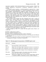
7. Specific Practices (Fig. 1)
6.8 Examination Sequence—Final penetrant examination
shall be performed after completion of all operations that could
cause surface-connected discontinuities or operations that
could expose discontinuities not previously open to the surface.
Such operations include, but are not limited to, grinding,
welding, straightening, machining, and heat treating.
6.8.1 Surface Treatment—Final penetrant examination may
be performed prior to treatments that can smear the surface but
not by themselves cause surface discontinuities. Such treatments include, but are not limited to, vapor blasting, deburring,
sanding, buffing, sandblasting, lapping, or peening. Performance of final penetrant examination after such surface treatments requires that etching be included in the precleaning
operation unless otherwise agreed on between the cognizant
engineering organization and the NDT facility.
7.1 Surface Preparation—All surfaces to be examined shall
be clean, dry, and free of soils, oil, grease, paint and other
coatings (except as allowed by 6.8.2), corrosion products,
scale, smeared metal, welding flux, chemical residues, or any
other material that could prevent the penetrant from entering
discontinuities, suppress dye performance, or produce unacceptable background. Cleaning methods, including etching,
selected for a particular component shall be consistent with the
NOTE 2—Final penetrant examination should always precede peening.
6.8.2 Surface Coatings—All coatings and other surface
conditions, such as, paint, plating, corrosion, etc. shall be
removed from the area to be examined prior to penetrant
examination. The penetrant examination shall precede any
surface finish, such as anodize, except for inservice parts that
may be examined without removing the anodize.
6.9 Material and Process Limitations—Not all penetrant
sensitivity levels, materials, and process methods are applicable to all examination requirements. The sensitivity level
shall be adequate for the intended purpose of the examination.
Unless there is an approval for deviation given by the cognizant engineering organization, the following selections are
mandatory or forbidden, as indicated:
6.9.1 Forms a and b (dry powder and water soluble)
developers shall not be used with Type II (visible dye)
penetrant systems. This is not intended to prohibit the use of a
Form f developer that has been qualified with a particular Type
II system in accordance with AMS 2644.
6.9.2 Type II penetrant examination shall not be used for
final acceptance examination of aerospace products. In
addition, Type II penetrant examination shall not be used prior
to a Type I penetrant examination of the same surface. This is
not intended to eliminate the use of in-process Type II
FIG. 1 Process Flow Chart
4
E1417/E1417M − 16
[30 cm], when possible between the spray nozzle and the part.
Washing shall be conducted under appropriate illumination.
Caution shall be exercised to ensure that over-washing does not
occur. If over-washing occurs, the component(s) shall be
thoroughly dried and reprocessed. After rinsing, drain water
from the component and utilize repositioning, suction, blotting
with clean absorbent materials, or filtered shop air at less than
25 psi [172 kPa] to prevent pooling in cavities, recesses, and
pockets. (Warning— Over-removal of the surface penetrant
shall require that the component be cleaned and reprocessed. A
good indicator of over-wash or over-removal of the surface
penetrant is evidenced by the total lack of residue that may
occur on all or a specific area of the part, see Test Method
E165.)
7.3.1.2 Automated Spray—For automated spray systems,
the wash parameters shall be such that the requirements of
7.8.3 are met. Water temperature shall be maintained between
50 to 100°F [10 to 38°C].
7.3.1.3 Manual Wipe—Excess penetrant shall be removed
with a clean, dry, lint-free cloth or absorbent toweling. The
remainder of the surface penetrant shall then be removed with
a water-dampened cloth or towel. The surface shall not be
flushed with water and the cloth or towel shall not be saturated
with water. The component shall be examined under appropriate illumination to ensure adequate removal of the surface
penetrant. The surface shall be dried by blotting with a clean,
dry towel or cloth, or by evaporation.
7.3.1.4 Immersion—Immersion wash may be utilized if the
water is air agitated and good circulation is maintained
throughout the wash operation. Water temperature shall be
maintained between 50 and 100°F [10 and 38°C].
7.3.2 Method B Process—Lipophilic post-emulsifiable penetrant shall be removed by air agitated water immersion or with
a water spray or hydro-air spray rinse after application of an
emulsifier and an appropriate emulsifier dwell time. Water
pressure and temperature and air pressure shall meet the
requirements specified in 7.3.1.1, 7.3.1.2, and 7.3.1.4.
7.3.2.1 Lipophilic emulsifiers shall be applied by immersion
or flowing. Lipophilic emulsifiers shall not be applied by spray
or brush and shall not be agitated while on the surface of the
component. Maximum dwell times, unless otherwise specified,
shall be 3 min for Type I systems and 30 s for Type II systems,
or as recommended by the manufacturer. Actual dwell times
shall be the minimum necessary to produce an acceptable
background on the component.
7.3.2.2 Rinsing—After the appropriate emulsifier dwell
time, emulsification shall be stopped by immersion or water
spray. For spray removal of the penetrant/emulsifier mixture,
the parameters of 7.3.1.1, 7.3.1.2, and 7.3.1.4 apply. Dwell
time in an agitated immersion rinse, if used, shall be the
minimum required to remove the emulsified penetrant. Examine the components under appropriate illumination after rinsing. Clean and reprocess those components with excessive
background. After rinsing, drain water from the component and
utilize repositioning, suction, blotting with clean absorbent
materials or filtered shop air at less than 25 psi [172 kPa] to
prevent pooling. Caution shall be exercised to ensure that the
air nozzle is held at a sufficient distance from the part to ensure
contaminants to be removed and shall not be detrimental to the
component or its intended function.
7.1.1 One or more appropriate cleaning methods such as
solvent cleaning, vapor degreasing, ultrasonic cleaning,
aqueous-based cleaning, or methods agreed upon with the
cognizant engineering organization shall be used for the
removal of oils, greases, and waxes, and as the final step before
penetrant examination. If etching is required, the parts shall be
appropriately cleaned, then etched and delivered to penetrant
examination.
7.1.2 Chemical cleaning shall be used for the removal of
paints, varnishes, scale, carbon, or other contaminants that are
not removable by solvent cleaning methods. (Warning—
Caution should be exercised when using chemicals because
they may irritate the eyes or skin.)
7.1.3 Mechanical cleaning shall be used for the removal of
soils and other contaminants that cannot be removed by solvent
or chemical cleaning methods.
7.1.4 Grit blasting without etching may be an acceptable
cleaning method if it can be demonstrated that a sufficiently
fine abrasive (150 grit or finer) will not cause peening and can
be removed by a detergent or alkaline cleaner.
7.1.5 Etching, unless otherwise specified, shall be performed when evidence exists that previous cleaning, surface
treatments, or service usage has produced a surface condition
that degrades the effectiveness of penetrant examination. Etching processes shall be developed and controlled to prevent
damage to the component under test. Etching is not required
for those features such as close tolerance holes, close tolerance
surfaces, faying surfaces, etc., where the function of the
component or assembly would be degraded. Etching is not
required for intermediate examination when the surface(s) are
not retained in the final part/component configuration or when
the final penetrant examination is preceded by etching.
7.2 Penetrant Application—Unless otherwise specified, the
entire surface of the component shall be covered with penetrant. Large components may be examined in sections. Penetrant shall be applied by spraying, dipping, brushing, or other
method to provide coverage as required. The component,
penetrant, and ambient temperatures shall all be in the range
from 40 to 125°F [4 to 52°C] unless otherwise specified.
7.2.1 Penetrant Dwell Time—The dwell time, unless otherwise specified, shall be a minimum of 10 min. For temperatures
between 40 and 50°F [4.4 and 10°C], dwell time shall be a
minimum of 20 min. It is recommended to rotate or otherwise
move components as necessary, during dwell to prevent
pooling of the penetrant. For dwell times greater than two
hours, the penetrant shall be reapplied as required.
7.3 Penetrant Removal:
7.3.1 Method A Process—Water-washable penetrants shall
be removed with a manual or automated water spray, or a
manual wipe, or an air agitated immersion wash.
7.3.1.1 Manual Spray—For handheld spray guns water pressure adequate to remove the penetrant shall be used but shall
not exceed 40 psi [275 kPa]. Water temperature shall be
between 50 to 100°F [10 to 38°C]. When hydro-air nozzles are
used the air pressure shall not exceed 25 psi [172 kPa]. A
coarse spray shall be used with a minimum distance of 12 in.
5
E1417/E1417M − 16
systems shall require the use of appropriate black light illumination to ensure adequate penetrant removal.
that the developing indication is not smeared by the air blast. If
over-emulsification is observed, the component must be
cleaned and reprocessed.
7.3.3 Method C Process—Solvent-removable penetrants are
removed by first wiping the excess penetrant with a clean,
lint-free, dry cloth or absorbent toweling. The remainder of the
surface penetrant is then removed with a solvent-dampened
lint-free cloth or towel. The surface of the component shall not
be flushed with solvent and the cloth or towel shall not be
saturated with solvent. The component and cloth or toweling
shall be observed under appropriate illumination to ensure
adequate removal of the surface penetrant. Over-removal of the
surface penetrant shall require the component to be cleaned and
reprocessed. The surface shall be dried by blotting with a
lint-free, dry cloth or towel, or by evaporation. Method C can
also be used for water-washable penetrants using water or
solvent for removal of excess penetrant.
7.3.4 Method D Process—Hydrophilic post emulsifiable
penetrant shall be removed with a water prerinse, application
of the hydrophilic emulsifier and then a postrinse.
7.3.4.1 Rinse—The water prerinse shall be applied for the
minimum amount of time required to achieve removal of the
bulk surface penetrant. The rinse parameters of 7.3.1.1 or
7.3.1.2 shall apply.
(1) For spray application of the emulsifier, a water prerinse
may be omitted.
7.3.4.2 Hydrophilic emulsifier shall be applied by
immersion, flowing, or spray. Hydrophilic emulsifier shall not
be applied by brush. Foaming application of hydrophilic
emulsifier is permissible when approved by the CEO.
(1) For immersion applications, the concentration, percent
volume, shall be no higher than specified by the penetrant
system supplier and shall not exceed that for which the system
was qualified. While immersed, the emulsifier or part should be
mildly agitated. Dwell time shall be the minimum required for
adequate surface penetrant removal, but unless otherwise
approved by the cognizant engineering organization, shall not
exceed 2 minutes.
(2) For spray or flowing applications, the concentration
shall not exceed 5 %. Spray applications may include fixed
spray nozzles, spray wands, pump sprayers, or spray bottles
provided the concentration is tested and meets the requirments
of 7.8.2.6. Dwell time shall be the minimum required for
adequate surface penetrant removal, but unless otherwise
approved by the cognizant engineering organization, shall not
exceed two minutes per surface area.
7.3.4.3 Postrinse—After the application and dwell of the
hydrophilic emulsifier, the component being examined shall be
rinsed with water. The spray rinse parameters of 7.3.1.1,
7.3.1.2, and 7.3.1.4 shall apply. Evidence of over-removal shall
require the part to be cleaned and reprocessed. Excessive
background may be removed by additional (touchup) application of the hydrophilic emulsifier provided its maximum
allowable dwell time is not exceeded. Additional rinsing of the
touch-up area will be required after application and dwell of
the hydrophilic emulsifier. If careful touch-up application of
the hydrophilic emulsifier does not produce an acceptable
background, the part shall be cleaned and reprocessed. Manual
7.4 Drying—The components shall be dried prior to the
application of dry developer, nonaqueous developer, or examination without developer. The components should be drained
of excess water but not dried before the application of aqueous
soluble or suspendable developers. The components shall be
dried after the application of aqueous developers.
7.4.1 Drying Parameters—Components shall be air dried at
room temperature or in a drying oven. Oven temperatures shall
not exceed that specified in 6.6.2. Drying time shall only be
that necessary to adequately dry the part. Components shall be
removed from the oven immediately after drying. Components
shall not be placed in the oven with pooled water or pooled
aqueous solutions/suspensions.
7.5 Developing—Unless otherwise specified, developers
shall be utilized for penetrant examination. Type I penetrants
that are qualified to AMS 2644 may be used without developer
under either one of the following conditions: manufacturing
examination of aluminum and magnesium castings classified
by AMS 2175A as Class 3 or 4, or with the expressed approval
of the cognizant engineering organization. Minimum and
maximum penetrant bleedout times without developer shall be
10 min and 2 h respectively. When developer is used, components that are not inspected before the maximum bleedout time
shall be cleaned and reprocessed. When developer is not used,
components that are not inspected before the maximum bleedout time shall be reprocessed.
7.5.1 Dry Developers—Components shall be dry before the
developer is applied. Dry developer shall be applied in such a
manner as to contact all surfaces to be inspected. Excess dry
developer may be removed after the development time by light
tapping or light air blow-off not exceeding 5 psi [34 kPa].
Minimum and maximum developer dwell times shall be 10 min
and 4 h, respectively. Dry developers shall not be used with
Type II penetrants.
7.5.2 Nonaqueous Developers—Components, or areas requiring examination, shall be dry before application of the
developer. Nonaqueous developer shall be applied by spraying.
For Type I penetrants, the developer shall be applied as a
uniform thin coating over the entire surface to be inspected.
For Type II penetrants, the developer shall be applied over the
entire surface to form a uniform, white coating to provide
suitable color contrast for the penetrant indications. The
uniformity and thickness of the developer coating is important
for both types of penetrant systems. If the developer coating
thickness is too heavy for Type I systems such that the metallic
surface is completely masked, the component shall be cleaned
and reprocessed. Unless otherwise specified, the minimum and
maximum development times for nonaqueous developers are
10 min and 1 h respectively. For nonaqueous suspendable
developer, the developer container shall be frequently agitated
between applications.
7.5.3 Aqueous Developer—Aqueous soluble developers
shall not be used with Type II penetrants or Type I, Method A
penetrants. Aqueous suspendable developers can be used with
both Type I and Type II penetrants. Aqueous developers may
be applied to the component after rinsing. Developers shall be
6
E1417/E1417M − 16
indication shall be carefully evaluated under appropriate lighting (white light for visible dye penetrant and black light for
fluorescent penetrant), after the required development or redevelopment time as applicable. Measure the indication size at its
largest dimension with a measuring device and the appropriate
light that meets the requirements of 6.6.1.
7.6.4.2 Discontinuity Sizing—When sizing discontinuities
for judgment against appropriate acceptance criteria, the area
may be carefully wiped with a solvent-dampened cotton swab
or brush, ensuring rapid evaporation so that the area for
examination is not flooded with solvent. Immediately measure
the discontinuity using a measuring or comparison device and
the appropriate light that meets the requirements of 6.6.1.
applied by spray, flowing, or immersion. The applied developer
shall not be allowed to puddle and shall completely cover all
surfaces to be inspected. Components shall be air dried or oven
dried to the requirements of 7.4.1. Minimum and maximum
development times, after the component is dry, are 10 min and
2 h. Aqueous suspendable developers must be either constantly
agitated to keep the particles from settling out of suspension or
they must be thoroughly agitated prior to use to ensure that
particles are in suspension.
7.6 Examination—The interpretation area shall meet the
appropriate requirements of 7.8.4.5. Components shall be
interpreted before the maximum developing time, and if
required by specific procedures, monitored periodically during
the developing time. Components not interpreted before the
maximum developing time shall be cleaned and reprocessed.
7.6.1 Type I Processes—Inspector’s vision shall be dark
adapted for a minimum of 1 min prior to examining components. Longer times for more complete adaptation should be
used if necessary. Inspectors shall not wear photochromic or
permanently darkened lenses while processing or reviewing
parts under black light. Black lights shall meet the requirements of 7.8.4.1. All areas of fluorescence shall be interpreted.
Components with no indications or only nonrelevant indications shall be accepted. Components with relevant indications
shall be evaluated with respect to the applicable acceptance
criteria. Components with excessive background fluorescence
shall be cleaned and reprocessed.
7.6.2 Type II Processes—All indications shall be interpreted. Components with no indications or only nonrelevant
indications shall be accepted. Components with relevant indications shall be evaluated with respect to the applicable
acceptance criteria. Components with excessive background
shall be cleaned and reprocessed.
7.6.3 Evaluation—All indications found during the examination shall be evaluated in accordance with specified acceptance criteria.
7.6.3.1 Indication Verification—If allowed by the specific
procedure, indications may be evaluated by wiping the indication with a solvent-dampened swab or brush, allowing the area
to dry, and redeveloping. Redevelopment time shall be at least
ten minutes, except nonaqueous redevelopment shall be three
minutes minimum. If no indication reappears, the original
indication is considered false. This procedure may be performed twice for any given original indication.
7.6.3.2 Discontinuity Removal—When allowed by the specific examination procedure, discontinuity(ies) may be removed by an approved procedure such as sanding, either
powered or manual, or grinding to determine the depth and
extent of the discontinuity(ies). After the mechanical operation,
the area shall be cleaned, etched (if permitted), and reexamined. The process used for reexamination shall be at least as
sensitive as the original process.
7.6.4 Sizing—If the acceptance criteria are written in terms
of indication sizes, the indication size shall be measured. If the
acceptance criteria is written in terms of discontinuity or flaw
sizes, the discontinuity shall be measured.
7.6.4.1 Indication Sizing—When sizing indications for judgment against appropriate acceptance criteria, the penetrant
7.7 Postcleaning—Components shall be cleaned after examination to remove developers and other examination material residues if these are detrimental to subsequent operations
or the components’ intended function.
7.8 Quality Control Provisions—This section provides the
controls necessary to ensure that the penetrant system, materials and equipment provide an acceptable level of performance. The frequencies of the required checks in Table 1 are
based on a facility operating daily. For facilities operating less
frequently, the frequency of daily and weekly checks and those
required at the start of each shift may be reduced accordingly,
but must be performed prior to processing of parts. Monthly
and quarterly checks shall be performed at the same frequency
as for full-time operations. The NDT facility may perform
these process control operations or contract for their performance with an independent, laboratory. Records of tests,
except as noted in Table 1, shall be maintained and available
for audit by the customer, the cognizant engineering
organization, or regulatory agencies. Penetrant materials that
are provided ready-for-use and do not require mixing to a
concentration, and are not recovered, or reused, or both, such
as materials packaged in aerosol containers, closed drums or
materials poured into containers for use and are not reused are
not subject to the in-use penetrant requirements of 7.8.2.
7.8.1 New Material Conformance—Prior to being placed
into use, the conformance of materials to the requirements of
AMS 2644 shall be verified, usually by a certified report from
the supplier. Use of materials not conforming to AMS 2644
shall require approval by the cognizant engineering organization prior to use and shall be allowed only when materials
conforming to AMS 2644 are inadequate for the particular
application.
7.8.2 Material Checks (In-Use)—The applicable tests specified in 7.8.2.1 through 7.8.2.9 shall be conducted on in-use
materials at the intervals specified in Table 1. Operators shall
be alert to any changes in performance, color, odor,
consistency, or appearance of all in-use penetrant materials and
shall conduct the appropriate checks and tests if they have
reason to believe the quality of the penetrant may have
deteriorated. Penetrant examination shall be conducted only
after acceptable quality of materials has been established.
7.8.2.1 Penetrant Contamination—The in-use penetrant materials shall be viewed as specified in Table 1 to determine if
any of the following conditions are evident: precipitates, waxy
deposits, white coloration, surface scum, or any other evidence
7
E1417/E1417M − 16
TABLE 1 Required Tests and Frequency
Tests
Penetrant ContaminationA
Penetrant Brightness
Water Content—
Water-Based Penetrant (Method A)
Water Content—
Non-Water-Based Penetrant (Method A)
Lipophilic Emulsifier Water ContentB
Hydrophilic Emulsifier Immersion,
Spray, or Flowing ConcentrationB
Dry Developer ConditionB
Aqueous Developer Contamination—
Soluble and Suspendable
Aqueous Developer Concentration—
Soluble and Suspendable
Penetrant System PerformanceC
Water-Washable Penetrant Removability
Emulsifier Removability
Comparative Penetrant Sensitivity
Black Light IntensityB
Black Light Integrity
Special UV lighting
Battery Powered UV-A lights
Visible Light Intensity
Light Meter CalibrationB
Examination Area CleanlinessA
Examination Area Ambient Light Intensity
Water Wash Pressure CheckA
Water Pressure Gage CalibrationB
Water Wash Temperature CheckA
Water Temperature Gage CalibrationB
Drying Oven CalibrationB
Air Pressure Gauge Check
Air Pressure Gauge Calibration
Frequency
Karl Fischer Method as described in Annex A1. If the water
content of the in-use penetrant exceeds 5 %, the penetrant shall
either be discarded or sufficient unused penetrant added to
reduce the water content to below 5 %.
7.8.2.5 Lipophilic Emulsifier Water Content—Water content
of lipophilic emulsifiers shall be checked at the intervals
specified in Table 1 in accordance with Test Method D95, Test
Method D6304, or the Karl Fischer method as described in
Annex A1. If the in-use emulsifier exceeds the water content of
the original (un-used) emulsifier by more than 5 % it shall be
discarded or corrected, as appropriate.
7.8.2.6 Hydrophilic
Emulsifier
Concentration—
Concentration of the emulsifier solution shall be checked at
initial makeup, during additions and at the intervals specified in
Table 1 using a refractometer. A longer period may be used if
a plan justifying this extension is prepared by the NDT facility
and approved by the CEO. Refractometer values obtained shall
be compared to actual values obtained from known concentrations of emulsifier. For immersion applications, the
concentration, as percent of volume, shall be no higher than
that specified by the penetrant system supplier and shall not
exceed that for which the system was qualified. For spray or
flowing applications, the concentration shall not exceed 5 %.
7.8.2.7 Dry Developer Condition—Recycled or reused dry
developer shall be checked as specified in Table 1 to check for
fluorescence and to ensure it is fluffy and not caked. Caked dry
developer is unsatisfactory and shall be replaced. To check for
fluorescence, apply a thin layer of in-use developer to a 4-in.
[10-cm] or greater flat test panel using the same method of
application used for production parts, and observe under a
black light. Dry developer exhibiting ten or more fluorescent
specks in a 4-in. [10-cm] diameter circle is unsatisfactory and
shall be replaced. The test panel selected shall be nonfluorescent and non-reflective and have a working surface color
which provides a good contrast with the developer powder.
7.8.2.8 Aqueous Developer Contamination—Soluble and
suspendable aqueous developers shall be checked as specified
in Table 1 for fluorescence and coverage. Immerse a clean
aluminum panel, about 3 by 10 in. [8 by 25 cm] in the in-use
developer, dry it, and observe it under a black light. Observed
fluorescence or failure to uniformly wet the panel is unsatisfactory and the developer shall be discarded or otherwise
corrected, as appropriate.
7.8.2.9 Aqueous Developer Concentration—Soluble and
suspendable aqueous developer concentration shall be maintained and checked with a hydrometer or in accordance with
the manufacturer’s instructions at the intervals specified in
Table 1. Concentration shall be in accordance with the manufacturer’s recommendation and shall be replaced or corrected
accordingly.
7.8.3 Penetrant System Performance—The penetrant system’s overall performance shall be checked as specified in
Table 1. The check shall be performed by processing a known
defect standard through the system using in-use penetrant,
emulsifier (if used) and developer and appropriate processing
parameters. The resulting indications will then be compared to
the indications obtained using unused penetrant, emulsifier (if
used) and developer. This comparison may be made with
Paragraph
Daily
Quarterly
Weekly
7.8.2.1
7.8.2.2
7.8.2.3
Monthly
7.8.2.4
Monthly
Weekly
7.8.2.5
7.8.2.6
Daily
Daily
7.8.2.7
7.8.2.8
Weekly
7.8.2.9
Daily
As required
per 7.8.3
As required
per 7.8.3
As required
per 7.8.3
Daily
Weekly
Daily
Prior to and
after use
Weekly
Semi-annually
Daily
Quarterly
Start of each
working shift
Semi-annually
Start of each
working shift
Semi-annually
Quarterly
Start of each
working shift
Semi-annually
7.8.3
7.8.3.2
7.8.3.3
7.8.3.4
7.8.4.1
7.8.4.1
7.8.4.2
6.7.4.1,
7.8.4.2(1)
7.8.4.3
7.8.4.4
7.8.4.5
7.8.4.5
7.8.4.6
7.8.4.6
7.8.4.6
7.8.4.6
7.8.4.7
7.8.4.9
7.8.4.9
A
Need not be recorded.
B
The maximum time between verifications or checks may be extended when
substantiated by technical data and approved by the Cognizant Engineering
Organization.
C
Not required for Method C examinations.
of contamination or breakdown. When any of the above
conditions are determined to be detrimental, the material shall
be discarded or otherwise corrected, as appropriate.
7.8.2.2 Penetrant Brightness—Brightness tests of in-use
fluorescent penetrants shall be conducted at the intervals
specified in Table 1. Tests shall be in accordance with Test
Method E1135 with a representative sample of the unused
penetrant serving as the reference. Brightness values less than
90 % of the unused penetrant brightness are unsatisfactory and
the in-use penetrants shall be discarded or otherwise corrected,
as appropriate.
7.8.2.3 Water Content of Water-Based Water-Washable
Penetrants—The water content of water-based Method A
penetrants shall be checked at the intervals specified in Table 1
using a refractometer. The water content must be maintained
according to the manufacturer’s recommendation.
7.8.2.4 Water Content of Non-Water-Based Water-Washable
Penetrants—Water content of non-water-based Method A penetrants shall be checked at the intervals specified in Table 1 in
accordance with Test Method D95, Test Method D6304, or
8
E1417/E1417M − 16
records of previously obtained indications or with a similar
known defect standard processed with unused materials from a
hold-out sample. When required by the CEO or when the
sensitivity or performance of the in-use materials falls below
the performance of the unused materials, the in-use materials
shall be checked in accordance with paragraphs 7.8.3.2 through
7.8.3.4 as appropriate, prior to conducting any further penetrant
examinations. Unacceptable materials shall be discarded or
otherwise corrected in accordance with the manufacturer’s
instruction.
7.8.3.1 Known Defect Standards—The known defect standard used shall be approved by the cognizant engineering
organization. The user shall establish and document effective
cleaning procedures based on the manufacturer’s instructions,
if applicable. The user shall ensure that cleaning of the
standards between uses is adequate and that physical changes
in the standard that make it unrepresentative of the indications
found using the hold-out sample are detected.
7.8.3.2 Water-Washable
(Method
A)
Penetrant
Removability—When required in accordance with 7.8.3, the
removability of water-washable (Method A) penetrants shall be
tested using a AMS 2644-specified test panel or any other
commercially available grit blasted panel. The test shall be
performed using a sample of unused penetrant serving as a
reference. Place a streak of the unused reference sample on one
portion of a panel and a separate streak of the in-use penetrant
on a separate area of the panel. Allow the panel to drain for five
minutes and then wash the panel using the temperature,
pressure and wash times in use on the examination line. Dry
the panel, coat with developer, and examine under UV light. If
the background of the in-use sample is visibly greater than that
of the reference, then the in-use penetrant shall be discarded or
otherwise corrected, as appropriate.
7.8.3.3 Emulsifier Removability—When required in accordance with 7.8.3, the removability of the in-use emulsifier shall
be tested using an unused sample of the same brand of
emulsifier serving as a reference. The test shall be conducted
using two test panels and processing parameters specified in
AMS 2644 or any other commercially available grit blasted
panel. The in-use emulsifier shall be used with the unused
penetrant on one panel and compared to the reference system
of unused emulsifier with unused penetrant on a second panel.
Allow both panels to drain for five minutes and then wash
using the temperature, pressure and wash times used on the
examination line. Dry both panels, coat with developer, and
examine under UV light. If the background is visibly greater
than that of the reference system the emulsifier shall be
discarded or otherwise corrected, as appropriate.
7.8.3.4 Comparative Penetrant Sensitivity—When required
in accordance with 7.8.3, the comparative sensitivity of in-use
penetrant shall be checked using the procedures in 7.8.3 except
that the check shall be performed by comparing the in-use
penetrant to the reference (hold-out) unused penetrant by
processing both with unused emulsifier, if applicable, and
unused developer. If the comparative sensitivity of the in-use
penetrant is noticeably less than the reference penetrant, the
in-use penetrant is unsatisfactory for use.
penetrant or for determining the sensitivity level of the penetrant neither
of which can be performed using a starburst-type panel.
7.8.4 Equipment Checks—The following equipment checks
shall be conducted at the intervals specified in Table 1 and
recorded, as required. Records shall be maintained and available for audit by the customer, cognizant engineering organization or regulatory agencies. The calibration of equipment
shall be traceable to the National Institute of Standards and
Technology (NIST) or other recognized national standards,
where applicable.
7.8.4.1 Black Lights—Portable, hand-held, permanently
mounted or fixed black lights used to inspect parts shall be
checked for intensity as specified in Table 1 or prior to use, and
after bulb replacement. A longer period may be used if a plan
justifying this extension is prepared by the NDT facility and
approved by the cognizant engineering organization. The
minimum acceptable intensity is 1000 µW/cm2 (10 W/m2) at
15 in. [38.1 cm] from the front of the filter to the face of the
sensor. Black lights shall be checked at the intervals specified
in Table 1 for cleanliness and integrity and shall be cleaned,
repaired or replaced as appropriate.
(1) Black lights that use an UV-A LED source shall comply
with the requirements of Practice E3022.
NOTE—Some UV-A sources other than mercury vapor, for
example, micro-discharge, LED, etc., have been shown to have
emission characteristics such as excessive visible light, and UV
intensity that may result in fluorescent fade, veiling glare, etc.,
all of which can significantly degrade examination reliability.
(2) Since visible light contamination may interfere with
UV-A inspection, it is recommended that a visible light
contamination be taken at the viewing surface, when the UV-A
lamp is on and is held at the angle and distance used for
interpretation. The white light reading shall not exceed 2 fc
[21.5 lx].
7.8.4.2 Special UV Lighting—As specified in Table 1 or
prior to use, the light intensity of UV pencil lamps, UV light
guides, borescopes or remote UV examination equipment shall
be measured at the expected working distance and shall
provide at least 1000 µW/cm2 (10 W/m2) at the intended
examination surface. When using borescopes or remote video
examination equipment, the image or interpretation area being
viewed shall have sufficient resolution to effectively evaluate
the area of examination.
(1) Battery powered black lights used to inspect parts shall
have their intensity measured prior to and at the end of each
use, inspection, shift or day as defined by the Written Procedures (see 6.7.4.1). The minimum UV light intensity shall be
1000 µW/cm2 at 15 in. [38.1 cm].
7.8.4.3 Visible Lights—For Type II visible dye
examinations, the lighting systems shall be checked at intervals
specified in Table 1 to ensure a minimum of 100 fc [1076 lx]
when measured at the examination surface.
7.8.4.4 Light Meters—Ultraviolet and visible light meters
shall be calibrated at intervals specified in Table 1 in accordance with MIL-STD-45662, ANSI/NCSL Z540-1, or
ISO 10012-1.
NOTE 4—More information on UV-A.visible lights and meters can be
found in ASTM E2297.
NOTE 3—This test is not for determining the absolute sensitivity of the
9
E1417/E1417M − 16
7.8.4.5 Examination Area—The interpretation area for stationary systems for Type I penetrants shall be checked as
specified in Table 1 and shall be clean and free from excessive
fluorescent contamination and excessive visible light background. The ambient visible light background shall be checked
at intervals specified in Table 1 or when any changes, or
construction, or both, in the interpretation area are made.
Ambient visible light shall not exceed 2 fc [21.5 lx] at the
examination surface.
7.8.4.6 Water Wash Operating Pressures/Temperatures—
Indicators and controls shall be checked as specified in Table 1
to ensure proper settings. Non-compliant water pressure and
temperature settings shall be adjusted to the proper settings
prior to performing penetrant examinations. Indicators and
controls shall be calibrated at intervals specified in Table 1 in
accordance with MIL-STD-45662, ANSI/NCSL Z540, or
ISO 10012.
7.8.4.7 Drying Oven Calibration—The temperature controlling device and the temperature indicating device, if separate
from the controller, on the drying oven shall meet the requirements of 6.6.2 and shall be calibrated at intervals specified in
Table 1 in accordance with the requirements of MIL-STD45662, ANSI/NCSL Z540, or ISO 10012.
7.8.4.8 Timers—Timing devices used to measure or monitor
processing times, such as dwell times and eye adaptation times,
need not be calibrated.
7.8.4.9 Air Pressure Gauges—Air pressure gauges that are
used to regulate air pressure of hydro-air spray guns, removal
of water prior to drying, and blow off of dry developer shall be
checked and calibrated at intervals specified in Table I and in
accordance with MIL-STD-45662, ANSI/NCSL Z540, or ISO
10012.
move such identification, the records accompanying the component shall be marked or shall specify components to the
applicable documents. The methods of marking are listed in
7.9.2. Marking shall conform to MIL-STD-792, unless otherwise specified.
7.9.2 Impression Stamping Ink Stamping, Dyeing, Laser
Marking, Vibro Engraving, Peening or Etching—The specific
method to be used shall be specified in the contract document
(purchase order, drawing, specification, and so forth). If not
specified, ink stamping shall be used. Marking shall be located
in areas adjacent to the part number or an area specified by the
contract documents.
7.9.3 Other Identification—Other means of identification,
such as tagging, may be applied when the construction, finish,
or functional requirements of the component preclude etching,
dyeing, or stamping. Items such as bolts, nuts, or other small
parts may be identified by conspicuously marking each package.
7.9.4 Symbols—Each component that has successfully
passed examination shall be marked as follows:
7.9.4.1 When etching or stamping is applicable, symbols
shall be used. The stamping may contain an identification
symbol or supplier number of the facility and a unique number
or symbol identifying the examiner. Except for specialized
applications, use the symbol “P” to denote 100 % examination.
All components, in the lot sampled, accepted on sampling basis
shall be marked with the symbol “P” enclosed by an ellipse.
7.9.4.2 When dyeing is used, maroon dye shall be used to
denote components accepted on a 100 % examination basis.
Yellow dye shall be used to denote a sampling basis when
sampling is permitted.
7.9 Marking and Identification—Components successfully
passing the penetrant examination shall be identified and
marked as follows:
7.9.1 Marking—Marking shall be applied in a manner and
location that is harmless to the component, or its intended
function, and to preclude removal, smearing, or obliteration by
subsequent handling. When subsequent processing would re-
8. Keywords
8.1 dye liquid penetrant examination; dye penetrant examination; fluorescent liquid penetrant examination; fluorescent
penetrant examination; liquid penetrant examination; liquid
penetrant testing; nondestructive; nondestructive evaluation;
nondestructive examination; nondestructive testing; penetrant
examination; penetrant testing
ANNEX
(Mandatory Information)
A1. METHOD FOR MEASURING WATER CONTENT
A1.2 Apparatus:
A1.1 Scope and Application—This modified Karl Fischer
volumetric procedure is a practical alternative to Test Method
D95 for undiluted hydrophilic emulsifiers and water contamination of in-use lipophilic emulsifiers and Method A penetrants. The amount of sample used is adjusted to meet the
water equivalent capacity of the titration agent employed (1
mL = 5 mg H2O). For most materials required to meet the five
percent (5 %) maximum allowable water content limit, 0.5 to
1.0 g sample size is sufficient.
A1.2.1 Buret, glass, 50-mL,
A1.2.2 Flask, wide-mouth Erlenmeyer type, 250-mL,
A1.2.3 Pipets, volumetric, two, 10-mL,
A1.2.4 Weighing scale, reads to at least two decimal places,
and
A1.2.5 White paper.
10
E1417/E1417M − 16
A1.4.5 Record titrant reading.
A1.3 Reagents:
A1.3.1 Buffer solution, Hydranal (Riedel de Haen) or
Hydra-Point (J.T. Baker), 500 mL,
A1.4.6 Place the flask on balance and add about 0.5 g of test
sample, and record weight. Gently swirl flask to mix sample.
A1.3.2 Titrant, Hydranal Composite 5 (Riedel de Haen) or
Hydra-Point Titrant 5, 1 L, and
A1.4.7 Place flask under buret and titrate back to the same
yellow-brown color and record the reading.
A1.3.3 Methanol, reagent grade, 500 mL.
A1.4.8 Repeat and average % H2O readings.
A1.4 Analytical Procedure:
A1.5 Calculate Water Content as follows:
A1.4.1 Charge buret with Hydranal titrant.
% H 2 O 5 @ consumption titrant 3 titer value 3 100# ÷sample weight
(A1.1)
A1.4.2 Pipet 10 mL of methanol into clean dry Erlenmeyer
flask.
where:
consumption
= second buret reading of Hydranal Composite 5 Titrant minus the first buret reading,
mL,
titer value
= 5 mg/mL H2O, mg/mL, and
sample weight = weight of sample added, mg.
A1.4.3 Pipet 10 mL of Hydranal buffer into the same flask
and gently swirl to mix.
A1.4.4 Place white paper below buret. Place the flask under
the buret and slowly titrate, with gently swirling the Hydranal
titrant into the flask until a light yellow-brown color persists
(about 3 mL).
A1.6 Repeat and average % H2O readings.
SUMMARY OF CHANGES
Committee E07 has identified the location of selected editorial changes to this standard since the last issue
(E1417/E1417M – 13) that may impact the use of this standard. (June 15, 2016).
(1) Added E3022 to the list of Reference Documents.
(2) Revised 6.6.1.2 and 7.8.4.1(1) to refer to E3022.
ASTM International takes no position respecting the validity of any patent rights asserted in connection with any item mentioned
in this standard. Users of this standard are expressly advised that determination of the validity of any such patent rights, and the risk
of infringement of such rights, are entirely their own responsibility.
This standard is subject to revision at any time by the responsible technical committee and must be reviewed every five years and
if not revised, either reapproved or withdrawn. Your comments are invited either for revision of this standard or for additional standards
and should be addressed to ASTM International Headquarters. Your comments will receive careful consideration at a meeting of the
responsible technical committee, which you may attend. If you feel that your comments have not received a fair hearing you should
make your views known to the ASTM Committee on Standards, at the address shown below.
This standard is copyrighted by ASTM International, 100 Barr Harbor Drive, PO Box C700, West Conshohocken, PA 19428-2959,
United States. Individual reprints (single or multiple copies) of this standard may be obtained by contacting ASTM at the above
address or at 610-832-9585 (phone), 610-832-9555 (fax), or (e-mail); or through the ASTM website
(www.astm.org). Permission rights to photocopy the standard may also be secured from the Copyright Clearance Center, 222
Rosewood Drive, Danvers, MA 01923, Tel: (978) 646-2600; />
11

![E:Tuan 16 CKTKN[2].doc](https://media.store123doc.com/images/document/2014_07/04/medium_nkp1382471123.jpg)