Astm e 1515 14
Bạn đang xem bản rút gọn của tài liệu. Xem và tải ngay bản đầy đủ của tài liệu tại đây (377.56 KB, 9 trang )
Designation: E1515 − 14
Standard Test Method for
Minimum Explosible Concentration of Combustible Dusts1
This standard is issued under the fixed designation E1515; the number immediately following the designation indicates the year of
original adoption or, in the case of revision, the year of last revision. A number in parentheses indicates the year of last reapproval. A
superscript epsilon (´) indicates an editorial change since the last revision or reapproval.
INTRODUCTION
This test method describes procedures for measuring the minimum concentration of a combustible
dust (dispersed in air) that is capable of propagating a deflagration. The tests are made in laboratory
chambers that have volumes of 20 L or larger.
2. Referenced Documents
1. Scope
2.1 ASTM Standards:2
D3173 Test Method for Moisture in the Analysis Sample of
Coal and Coke
D3175 Test Method for Volatile Matter in the Analysis
Sample of Coal and Coke
E681 Test Method for Concentration Limits of Flammability
of Chemicals (Vapors and Gases)
E1226 Test Method for Explosibility of Dust Clouds
1.1 This test method covers the determination of the minimum concentration of a dust-air mixture that will propagate a
deflagration in a near-spherical closed vessel of 20 L or greater
volume.
NOTE 1—The minimum explosible concentration (MEC) is also referred to as the lower explosibility limit (LEL) or lean flammability limit
(LFL).
1.2 Data obtained from this test method provide a relative
measure of the deflagration characteristics of dust clouds.
2.2 CEN/CENELEC Publications:3
EN 14034–3 Determination of Explosion Characteristics of
Dust Clouds – Part 3: Determination of the Lower
Explosion Limit LEL of Dust Clouds
1.3 This test method should be used to measure and describe
the properties of materials in response to heat and flame under
controlled laboratory conditions and should not be used to
describe or appraise the fire hazard or fire risk of materials,
products, or assemblies under actual fire conditions. However,
results of this test may be used as elements of a fire risk
assessment that takes into account all of the factors that are
pertinent to an assessment of the fire hazard of a particular end
use.
3. Terminology
1.5 This standard does not purport to address all of the
safety concerns, if any, associated with its use. It is the
responsibility of the user of this standard to establish appropriate safety and health practices and determine the applicability of regulatory limitations prior to use. Specific precautionary statements are given in Section 8.
3.1 Definitions of Terms Specific to This Standard:
3.1.1 dust concentration, n—the mass of dust divided by the
internal volume of the test chamber.
3.1.2 (dP/dt)ex, n—the maximum rate of pressure rise during
the course of a single deflagration test.
3.1.3 minimum explosible concentration (MEC), n—the
minimum concentration of a combustible dust cloud that is
capable of propagating a deflagration through a well dispersed
mixture of the dust and air under the specified conditions of
test.
3.1.4 Pignition, n—the absolute pressure at the time the
ignitor is activated, see Fig. 1.
3.1.5 ∆Pignitor, n—the pressure rise in the chamber due to
the ignitor by itself in air at atmospheric pressure
1
This test method is under the jurisdiction of ASTM Committee E27 on Hazard
Potential of Chemicals and is the direct responsibility of Subcommittee E27.05 on
Explosibility and Ignitability of Dust Clouds.
Current edition approved Dec. 1, 2014. Published January 2015. Originally
approved in 1993. Last previous edition approved in 2007 as E1515 – 07. DOI:
10.1520/E1515-14.
2
For referenced ASTM standards, visit the ASTM website, www.astm.org, or
contact ASTM Customer Service at For Annual Book of ASTM
Standards volume information, refer to the standard’s Document Summary page on
the ASTM website.
3
Available from European Committee for Standardization (CEN), Avenue
Marnix 17, B-1000, Brussels, Belgium, .
1.4 The values stated in SI units are to be regarded as
standard. No other units of measurement are included in this
standard.
Copyright © ASTM International, 100 Barr Harbor Drive, PO Box C700, West Conshohocken, PA 19428-2959. United States
1
E1515 − 14
FIG. 1 Typical Recorder Tracings for a Weak Dust Deflagration in a 20-L Chamber, using a 2500 J Ignitor
4.2 Ignition of this dust-air mixture is then attempted after a
specified delay time by an ignition source located near the
center of the chamber.
3.1.6 Pex,a, n—the maximum explosion pressure (absolute)
reached during the course of a single deflagration test (see Figs.
1 and 2).
3.1.7 Pm, n—maximum pressure rise produced during the
course of a single deflagration test that is corrected for the
effects of ignitor pressure and cooling in the 20-L vessel (see
Test Method E1226, Sections X1.8 and X1.9).
3.1.7.1 Discussion—When testing in the Siwek 20-L vessel
(see Test Method E1226, Appendix X1) PR may be calculated
using the corrected explosion pressure:
PR 5 ~ P m 1 P ignition ! ⁄P ignition
3.1.8 pressure ratio (PR), n—defined as:
PR 5 ~ P ex,a 1 ∆ P ignitor ! ⁄P ignition
4.3 The pressure time curve is recorded on a suitable piece
of equipment.
5. Significance and Use
5.1 This test method provides a procedure for performing
laboratory tests to evaluate relative deflagration parameters of
dusts.
(1)
5.2 The MEC as measured by this test method provides a
relative measure of the concentration of a dust cloud necessary
for an explosion.
(2)
4. Summary of Test Method
5.3 Since the MEC as measured by this test method may
vary with the uniformity of the dust dispersion, energy of the
ignitor, and propagation criteria, the MEC should be considered a relative rather than absolute measurement.
4.1 A dust cloud is formed in a closed combustion chamber
by an introduction of the material with air. The test is normally
made at atmospheric pressure.
FIG. 2 Typical Recorder Tracings for a Moderate Dust Deflagration in a 20-L Chamber, using a 2500 J Ignitor
2
E1515 − 14
7.4 Optical dust probes, such as those described in
Footnotes7,8 may be used to monitor the uniformity of the dust
dispersion.
5.4 If too weak an ignition source is used, the measured
MEC would be higher than the “true” value. This is an
ignitability limit rather than a flammability limit, and the test
could be described as “underdriven.” Ideally, the ignition
energy is increased until the measured MEC is independent of
ignition energy. However, at some point the ignition energy
may become too strong for the size of the test chamber, and the
system becomes “overdriven.” When the ignitor flame becomes too large relative to the chamber volume, a test could
appear to result in an explosion, while it is actually just dust
burning in the ignitor flame with no real propagation beyond
the ignitor.
7.5 The pressure transducer and recording equipment must
have a combined response rate that is greater than the maximum measured rate of pressure rise.
7.6 An example of a chamber and specific procedures that
have been found suitable are shown in Appendix X1.
NOTE 2—Another 20 L chamber design is described in Appendix X1 of
Test Method E1226.
8. Safety Precautions
5.5 The recommended ignition source for measuring the
MEC of dusts in 20-L chambers is a 2500 or 5000 J
pyrotechnic ignitor.4 Measuring the MEC at both ignition
energies will provide information on the possible overdriving
of the system.5 To evaluate the effect of possible overdriving in
a 20-L chamber, comparison tests may also be made in a larger
chamber, such as a 1 m3-chamber.
8.1 Prior to handling a dust, the toxicity of the sample and
its combustion products must be considered. This information
is generally obtained from the manufacturer or supplier.
Appropriate safety precautions must be taken if the material
has toxic or irritating characteristics. Tests using this apparatus
should be conducted in a ventilated hood or other area having
adequate ventilation.
5.6 If a dust ignites with a 5000 J ignitor but not with a 2500
J ignitor in a 20-L chamber, this may be an overdriven system.5
In this case, it is recommended that the dust be tested with a
10 000 J ignitor in a larger chamber, such as a 1 m3-chamber,
to determine if it is actually explosible.
8.2 Before initiating a test, a physical check of all gaskets
and fittings should be made to prevent leakage.
8.3 If chemical ignitors are used as an ignitor source, safety
in handling and use is a primary consideration. Premature
ignition by electrostatic discharge must be considered a possibility. When handling these ignitors, eye protection must be
worn at all times. A grounded, conductive tabletop is recommended for preparation. Federal, state, and local regulations
for the procurement, use, and storage of chemical ignitors must
be followed.
5.7 The values obtained by this test method are specific to
the sample tested (particularly the particle size distribution)
and the method used and are not to be considered intrinsic
material constants.
6. Interferences
8.4 All testing should initially be conducted with small
quantities of sample to prevent overpressurization due to high
energy material.
6.1 Unburned dust or combustion products remaining in the
chamber or disperser from a previous test may affect results.
The chamber and disperser should both be cleaned thoroughly
before each test is made.
8.5 Explosive, highly reactive, or easily decomposed materials should not be tested unless they have been characterized
by prior testing. Procedures such as the use of barricades,
hoods, and personal protective equipment should be used as
judgment indicates.
7. Apparatus
7.1 The equipment consists of a closed steel combustion
chamber with an internal volume of at least 20 L, spherical or
cylindrical (with a length to diameter ratio between 1.3:1 and
0.7:1) in shape.
9. Sampling, Test Specimens, and Test Units
9.1 It is not practical to specify a single method of sampling
dust for test purposes because the character of the material and
its available form affect selection of the sampling procedure.
Generally accepted sampling procedures should be used as
described in MNL 32.9
7.2 The vessel should be designed and fabricated in accordance with the ASME Boiler and Pressure Vessel Code,
Section VIII.6 A maximum allowable working pressure
(MAWP) of at least 15 bar is recommended.
9.2 Tests may be run on an as-received sample. However,
due to the possible accumulation of fines at some location in a
processing system, it is recommended that the test sample be at
least 95 % minus 200 mesh (75 µm).
7.3 The apparatus must be capable of dispersing a fairly
uniform dust cloud of the material.
4
The pyrotechnic ignitors are available commercially from Cesana Corp., PO
Box 182, Verona, NY 13478, or from Fr. Sobbe, GmbH, Beylingstrasse 59, Postfach
140128, D-4600 Dortmund-Derne, Germany.
5
Cashdollar, K. L., and Chatrathi, K., “Minimum Explosible Dust Concentrations Measured in 20-L and 1-m3 Chambers,” Combustion Science and Technology,
Vol 87, 1993, pp. 157–171.
6
Available from American Society of Mechanical Engineers (ASME), ASME
International Headquarters, Three Park Ave., New York, NY 10016-5990, http://
www.asme.org.
7
Cashdollar, K. L., Liebman, I., and Conti, R. S., “Three Bureau of Mines Dust
Probes,” RI 8542, U.S. Bureau of Mines, 1981.
8
Conti, R. S., Cashdollar, K. L., and Liebman, I., “Improved Optical Dust Probe
for Monitoring Dust Explosions,” Review of Scientific Instruments, Vol 53, 1982, pp.
311–313.
9
MNL 32, Manual on testing Sieving Methods, is available from ASTM
Headquarters, 100 Barr Harbor Drive, West Conshohocken, PA 19428.
3
E1515 − 14
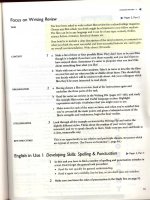
minus 200 mesh, a mass median diameter of ;48 µm, and
36 % volatility. The lycopodium is a natural plant spore having
a narrow size distribution with 100 % minus 200 mesh and a
mass median diameter of ;28 µm. The gilsonite has ;91 %
minus 200 mesh, a mass median diameter of ;28 µm, and
84 % volatility. The polyethylene has ;98 % minus 200 mesh,
a mass median diameter of ;29 µm, and 100 % volatility.
9.3 To achieve this particle fineness (≥95 % minus 200
mesh), the sample may be ground or pulverized or it may be
sieved.
NOTE 3—The operator should consider the thermal stability and the
friction and impact sensitivity of the dust during any grinding or
pulverizing. In sieving the material, the operator must verify that there is
no selective separation of components in a dust that is not a pure
substance.
10.3 In addition to the initial calibration and standardization
procedure, at least one reference dust sample should be retested
periodically to verify that the dispersion and other characteristics of the chamber have not changed.
9.4 Dust samples that are much finer than 200 mesh (75 µm)
may have even lower MEC values.
NOTE 4—It may be desirable in some cases to conduct dust deflagration
tests on materials as sampled from a process because process dust streams
may contain a wide range of particle sizes or have a well-defined specific
moisture content. Materials consisting of a mixture of chemicals may be
selectively separated on sieves and certain fibrous materials that may not
pass through a relatively coarse screen may produce dust deflagrations.
When a material is tested in the as-received state, it should be recognized
that the test results may not represent the most severe dust deflagration
possible. Any process change resulting in a higher fraction of fines than
normal or drier product than normal may increase the explosion severity.
11. Procedure
11.1 These general procedures are applicable for all suitable
chambers. The detailed procedures specific to each chamber
are listed in Appendix X1.
11.2 Inspect equipment to be sure it is thoroughly clean and
in good operational condition.
9.5 The moisture content of the test sample should not
exceed 5 % in order to avoid test results of a given dust being
noticeably influenced.
NOTE 6—A high frequency of tests could increase the operating
temperature in some chambers. Tests should not be run at chamber
temperatures more than 20°C above ambient as this may affect the
measured MEC value.
NOTE 5—There is no single method for determining the moisture
content or for drying a sample. ASTM lists many methods for moisture
determination in the Annual Book of ASTM Standards. Sample drying is
equally complex due to the presence of volatiles, lack of or varying
porosity (see Test Methods D3173 and D3175), and sensitivity of the
sample to heat. Therefore, each must be dried in a manner that will not
modify or destroy the integrity of the sample. Hygroscopic materials must
be desiccated.
11.3 Ensure that the oxygen content of the dispersion air is
20.9 6 0.5 %. Higher or lower oxygen contents will affect the
MEC value.
NOTE 7—The oxygen content of some synthetic air cylinders may range
from 19 to 26 %.
11.4 Place a weighed amount of dust in the disperser
according to detailed instructions in Appendix X1.
10. Calibration and Standardization
10.1 Because a number of factors (uniformity of dispersion,
ignition energy, sample age, etc.) can affect the test results, any
test vessel design other than that listed in Appendix X1 must be
standardized using dust samples whose minimum explosible
concentrations are known. A minimum of five dust samples
over a range of MEC values is required. The MEC for each
dust must agree to within 610 % or 5 g/m3, whichever is
larger. The comparison must be made using the same dust,
ignitor energy, and chamber volume.
11.5 Place ignition source in the chamber. The recommended ignition source for measuring the MEC in 20-L
chambers is a 2500 or 5000 J pyrotechnic ignitor (see 5.4 –
5.6).
11.6 Seal chamber; all valves must be closed.
11.7 Partially evacuate chamber so that, after addition of
dispersing air, the desired normal chamber pressure of 1 bar
absolute will be reached prior to initiation of the deflagration
test.
10.2 Representative MEC data in grams per cubic metre
(g/m3) for five dusts samples are listed as follows:
Bureau of Mines
20-L ChamberA
Bituminous coal, Pocahontas seam
Bituminous coal, Pittsburgh seam
Lycopodium
Gilsonite
Polyethylene
11.8 Actuate the timing circuit to conduct the test.
Fike
1 m3 ChamberB
2500 J
5000 J
10 000 J
120
80
45
35
32
85
60
30
30
28
...
80
42
36
...
NOTE 8—The dust sample is automatically dispersed through a dispersion system in the chamber. The deflagration is then initiated when a
defined ignition delay time has elapsed. This effective ignition delay time,
td, is the length of time between the first pressure rise due to dust
dispersion and the moment normal pressure has been reached in the
chamber and ignition is activated (see Fig. 1). The length of this time
defines the degree of turbulence and in some cases the concentration of the
dust dispersed in the chamber at the moment of ignition.
A
20-L Chamber at Pittsburgh, PA. See Appendix X1 and Cashdollar, K. L. and
Hertzberg, M. “20-L Explosibility Test Chamber for Dusts and Gases,” Review of
Scientific Instruments, Vol 56, 1985, pp. 596–602.
B
1-m3 Chamber at Blue Springs, MO. See Cashdollar, K. L. and Chatrathi, K.,
“Minimum Explosible Concentrations in 20-L and 1-m3 Chambers,” Combustion
Science and Technology, Vol 87, 1993, pp. 157–171.
11.9 Record pressure time curve on a suitable piece of
equipment, such as a high speed chart recorder, storage
oscilloscope, or computer-based data acquisition system. Obtain the explosion data, Pignition, Pex,a, and dP/dtex, according to
Figs. 1 and 2.
The Pocahontas seam bituminous coal has ;75 % minus
200 mesh, a mass median diameter of ;52 µm, and 17 %
volatility. The Pittsburgh seam bituminous coal has ;80 %
11.10 After the test, open a valve to vent pressure from the
chamber. Open the chamber, remove residue, and thoroughly
clean the chamber and dispersion system.
4
E1515 − 14
11.11 It is recommended that an initial concentration of 100
g/m3 be tested. If the initial concentration produces a
deflagration, decrease the concentration until no deflagration
occurs (see Fig. 3). If the initial concentration does not produce
a deflagration, increase the concentration in steps of 100 g/m3
until a deflagration is obtained.
NOTE 9—The rate of pressure rise can be size-normalized by multiplying by the cube root of the chamber volume, giving (dP/dt)ex V1/3.
12.4 The pressure ratio is: PR = (Pex,a – ∆Pignitor)/Pignition.
12.5 The PR (or Pex,a – ∆Pignitor) data and (dP/dtex)V1/3 (or
dP/dtex) data are then plotted as a function of concentration as
shown in Fig. 3.
11.12 For the final determination of the MEC, the concentration increments should be no greater than 25 % of the MEC.
It is necessary that at least two tests be made at each
concentration near the MEC.
12.6 The minimum explosible concentration (MEC) is defined as the lowest concentration for which PR ≥ 2.0. The MEC
is usually rounded to the nearest 5 g/m3 or 10 %, whichever is
larger. For the example shown in Fig. 3, the MEC would be 120
g/m3.
11.13 Plot the explosibility data from individual tests versus
dust concentration as shown in Fig. 3.
NOTE 10—For most dusts, the rich explosibility limit is at a concentration of greater than several thousand grams per cubic metre.10
Therefore, it is usually not practical to try to measure the rich limit for
dusts. This is in contrast to the normal rich limits of gases as measured by
Test Method E681.9
12. Calculation
12.1 The dust concentration is the mass of dust divided by
the volume of the test chamber.
12.7 If testing in a Siwek 20-L vessel from Test Method
E1226, Appendix X1, and using the corrected explosion
pressure Pm to evaluate PR (see the Discussion in 3.1.7), the
PR less than 2 criterion is equivalent to a criterion of Pm less
than 1 bar(g) when the ignition pressure Pignition is nominally 1
bar(a) (between 940 and 1060 mbar(a)). More generally, the
PR less than 2 criterion is equivalent to a criterion of Pm less
than the ignition pressure Pignition for all values of Pignition.
12.2 Determine pressures and rates of pressure rise from
pressure-time records. Figs. 1 and 2 are typical records from
which these values are obtained. Pignition is the absolute
pressure in the chamber at the time of ignition. The value of
Pex,a for a test at a given concentration is the highest deflagration pressure (absolute) as shown in Fig. 1(a) and 2(a). The
value of dP/dtex for a given test is the maximum slope of the
pressure trace (see Fig. 2(a)) or the highest value on the rate of
pressure rise trace (see Fig. 2(b)).
12.8 An alternative to the procedures in 12.5 and 12.6 is to
plot the pressure rise ([P ex,a 2P ignition 2∆P ignitor ] or Pm if using
the Siwek Chamber) as a function of concentration. In this
case, the MEC is the interpolated concentration for which the
pressure rise equals 1 bar, gauge.
12.3 If a low dP/dt is obtained (see Fig. 1(b)), a weak
deflagration may have occurred. Under these conditions, it is
important that the dP/dt measurement is not taken from the
ignition source but from the dust-air mixture itself. In order for
a test to be considered a deflagration, there must be a
measureable dP/dt, beyond the effects of the ignitor.
12.9 The values of ∆Pignitor and (dP/dt)ignitor for the ignition
source by itself must be established in the apparatus.
NOTE 11—The European method of limiting explosible concentration
determination EN 14034–3 uses an ignition/explosion criterion of Pex,a –
Pignition ≥ 0.3 bar in the 1-m3 chamber using two 5-kJ ignitors as an
ignition source and Pex,a – Pignition ≥ 0.5 bar in the 20-L chamber using two
1-kJ ignitors as an ignition source. As a result direct comparisons of
ASTM MEC determinations and European CEN/CENELEC LEL determinations may not be possible.
13. Report
13.1 Report the following information:
13.1.1 Complete identification of the materials tested; including type of dust, source, code numbers, forms, and
previous history,
13.1.2 Particle size distribution of the sample as received
and as tested,
13.1.3 Moisture or volatile content, or both, of the asreceived and as-tested material, if applicable,
13.1.4 Minimum explosible concentration,
13.1.5 Test pressure, that is, pressure at time of ignition,
13.1.6 Type and energy of the ignition source, and
13.1.7 Test chamber used and any deviation from the
normal procedure.
FIG. 3 Explosibility Test Data as a Function of Concentration for
a Typical Dust in a 20-L Chamber, using a 2500 J Ignitor
10
Cashdollar, K. L., and Hertzberg, M., “20-L Explosibility Test Chamber for
Dusts and Gases,” Review of Scientific Instruments, Vol 56, 1985, pp. 596–602.
5
E1515 − 14
14.2 Bias—Because the values obtained are relative measures of deflagration characteristics, no statement on bias can
be made.
13.2 If the dust does not ignite (according to the criterion in
12.6 and 12.8) at any of the dust concentrations tested, report
this fact and the range of dust concentrations tested.
14. Precision and Bias
15. Keywords
14.1 Precision—Measurement of the MEC of a dust should
be repeatable to within 610 % for a particular ignitor.
15.1 dust explosion; minimum explosible concentration
APPENDIX
(Nonmandatory Information)
X1. BUREAU OF MINES 20-L CHAMBER
X1.1 General Description
X1.1.1 Figs. X1.1 and X1.2 are vertical and horizontal cross
section drawings of the Bureau of Mines 20-L explosibility test
chamber. Further details on the chamber and its operation may
be found in Footnotes5,10.
X1.1.2 The chamber is made of Type 304 stainless steel and
has a pressure rating of 21 bar. It has a volume of 20 L and a
FIG. X1.2 Horizontal Cross Section of Bureau of Mines 20-L
Chamber
wall thickness of 13 mm. The hinged top is secured with six
19-mm-diameter steel bolts that are not shown on the drawings.
X1.1.3 One or two optical dust probes (see Footnotes7,8) are
used to monitor the uniformity of the dust dispersion. The
optical probes measure the transmission over a 38-mm path
length through the dust cloud. Thin jets of air keep the
windows of the probes clean.
X1.1.4 The absolute pressure is measured with a strain gage
pressure transducer.
X1.1.5 The data from the various instruments are collected
by a high speed personal computer-based data acquisition
system. It can sample data from 16 channels at a maximum rate
of 9 kHz if all channels are used or at faster rates if fewer
channels are used.
FIG. X1.1 Vertical Cross Section of Bureau of Mines 20-L Chamber
6
E1515 − 14
initiated, the ignitor flame will shoot across the center of the
chamber to the opposite wall.
X1.2.3 After the dust and ignitor have been placed in the
chamber, secure the top of the chamber with the six bolts.
X1.2.4 Partially evacuate the chamber to 0.14 bar absolute.
X1.2.5 Start the automatic timing sequence. A short blast of
air (0.3 s duration at 9 bar from the reservoir) disperses the dust
and returns the chamber pressure to about 1 bar absolute. There
is a 0.1 s delay after dispersion before the ignitor is activated.
The personal computer automatically collects the data and
displays them after the test.
X1.2.6 After the test, the chamber is vented and thoroughly
cleaned.
X1.1.6 The dispersion air comes from a 16-L reservoir (see
Fig. X1.3) that is connected by tubing to the chamber. A
solenoid valve and a swing check valve are in the air line.
X1.1.7 The standard ignitors are electrically activated, pyrotechnic ignitors with energies of 1000, 2500, or 5000 J.
These ignitors contain a mixture of 40 % zirconium, 30 %
barium nitrate, and 30 % barium peroxide. See also Figs. X1.4
and X1.5.
X1.2 Test Procedures
X1.2.1 Calculate and weigh the amount of dust necessary to
give the desired dust cloud concentration in the 20-L chamber.
Place the dust in the dispersion nozzle or on top of the nozzle
if there is too much dust to fit in the nozzle or if the dust
particles are too large for the holes in the nozzle.
X1.3 Calculation
X1.3.1 The minimum explosible concentration (MEC) is
defined as the lowest concentration for which PR ≥ 2.0 and
X1.2.2 Place the ignitor in the ignitor holder, which is at a
height of 17 cm and is 7 cm from the center axis. When
FIG. X1.3 Schematic of Bureau of Mines 20-L Chamber, Showing Air Reserve Cylinder and Dispersion Plumbing
7
E1515 − 14
FIG. X1.4
Machine Drawings of Bureau of Mines 20-L Chamber
(dP/dt)V1/3 ≥ 1.5 bar·m/s. The second part of the criterion is
added to require that there be some real propagation of the dust
flame and not just a pressure rise due to dust burning within the
ignitor flame. This additional MEC criterion for the Bureau of
Mines 20-L chamber partially corrects for the possible overdriving (see 5.4 – 5.6) of the 20-L system by strong ignitors.5
8
E1515 − 14
FIG. X1.5 Machine Drawings of Window Flanges and Dispersion Systems for Bureau of Mines 20-L Chamber
ASTM International takes no position respecting the validity of any patent rights asserted in connection with any item mentioned
in this standard. Users of this standard are expressly advised that determination of the validity of any such patent rights, and the risk
of infringement of such rights, are entirely their own responsibility.
This standard is subject to revision at any time by the responsible technical committee and must be reviewed every five years and
if not revised, either reapproved or withdrawn. Your comments are invited either for revision of this standard or for additional standards
and should be addressed to ASTM International Headquarters. Your comments will receive careful consideration at a meeting of the
responsible technical committee, which you may attend. If you feel that your comments have not received a fair hearing you should
make your views known to the ASTM Committee on Standards, at the address shown below.
This standard is copyrighted by ASTM International, 100 Barr Harbor Drive, PO Box C700, West Conshohocken, PA 19428-2959,
United States. Individual reprints (single or multiple copies) of this standard may be obtained by contacting ASTM at the above
address or at 610-832-9585 (phone), 610-832-9555 (fax), or (e-mail); or through the ASTM website
(www.astm.org). Permission rights to photocopy the standard may also be secured from the Copyright Clearance Center, 222
Rosewood Drive, Danvers, MA 01923, Tel: (978) 646-2600; />
9