Astm f 521 16
Bạn đang xem bản rút gọn của tài liệu. Xem và tải ngay bản đầy đủ của tài liệu tại đây (349.55 KB, 9 trang )
Designation: F521 − 16
Standard Test Methods for
Bond Integrity of Transparent Laminates1
This standard is issued under the fixed designation F521; the number immediately following the designation indicates the year of original
adoption or, in the case of revision, the year of last revision. A number in parentheses indicates the year of last reapproval. A superscript
epsilon (´) indicates an editorial change since the last revision or reapproval.
3.1.3 interlayer, n—transparent material used as the bonding
agent between two or more hard, transparent materials.
1. Scope
1.1 These test methods cover determination of the bond
integrity of transparent laminates. The laminates are usually
made of two or more glass or hard plastic sheets held together
by an elastomeric material. These test methods are intended to
provide a means of determining the strength of the bond
between the glass or plastic and the elastomeric interlayer
under various mechanical or thermal loading conditions.
3.2 Definitions of Terms Specific to This Standard:
3.2.1 number of plies, n—a three-ply laminate is one having
two transparent glass or plastic plies and one interlayer ply. A
five-ply laminate has three glass or plastic plies and two
interlayer plies.
4. Significance and Use
1.2 The test methods appear as follows:
Test
Test
Test
Test
Test Methods
Method A—Flatwise Bond Tensile Strength
Method B—Interlaminar Shear Strength
Method C—Creep Rupture
Method D—Thermal Exposure
4.1 These test methods provide a means to measure quantitatively the bond integrity between the outer layers of the
transparency and the interlayer, or to measure the cohesive
properties of the interlayer, under various loading conditions.
Sections
5 – 11
12 – 17
18 – 25
26 – 30
4.2 These test methods provide empirical results useful for
control purposes, correlation with service results, and as
quality control tests for acceptance of production parts.
1.3 This standard does not purport to address all of the
safety concerns, if any, associated with its use. It is the
responsibility of the user of this standard to establish appropriate safety and health practices and determine the applicability of regulatory limitations prior to use.
4.3 Test results obtained on small, laboratory-size samples
shown herein are indicative of full-size part capability, but not
necessarily usable for design purposes.
2. Referenced Documents
TEST METHOD A—FLATWISE BOND TENSILE
STRENGTH
2.1 ASTM Standards:2
D952 Test Method for Bond or Cohesive Strength of Sheet
Plastics and Electrical Insulating Materials
2.2 ANSI Standard:3
B1.1 Standard for Unified Screw Threads
5. Summary of Test Method
5.1 The bond is subjected to a mechanical load in a direction
perpendicular to the plane of the bond. The adhesive or
cohesive strength between the interlayer and the outer layers
(flatwise tensile strength) is determined, and expressed in terms
of pascals (or pounds-force per square inch).
3. Terminology
3.1 Definitions:
3.1.1 delamination, n—a visible separation between two
layers of bonded material.
3.1.2 face plies, n—transparent glass or plastic outer materials joined together with an interlayer.
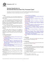
6. Apparatus
6.1 Metal Blocks—A pair of 50-mm (2-in.) square metal
blocks of 24 ST aluminum alloy, each having a maximum
height of 50 mm (2 in.). Each block shall have in one end a
hole (see Fig. 1) tapped 22.2 mm (7⁄8 in.) in accordance with
ANSI B1.1, to accommodate threaded 22.2-mm (7⁄8-in.) studs
of convenient length (see Test Method D952). Alternative
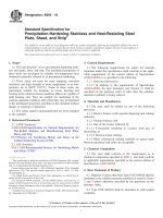
metal blocks utilize an aluminum “T” section, cut to 50 mm
(2 in.) square. A hole shall be drilled in the upright section of
each “T” block (see Fig. 2) to accommodate a metal pin or
holding device compatible with the test machine used.
1
These test methods are under the jurisdiction of ASTM Committee F07 on
Aerospace and Aircraft and are the direct responsibility of Subcommittee F07.08 on
Transparent Enclosures and Materials.
Current edition approved April 1, 2016. Published April 2016. Originally
approved in 1977. Last previous edition approved in 2010 as F521 – 83 (2010).
DOI: 10.1520/F0521-16.
2
For referenced ASTM standards, visit the ASTM website, www.astm.org, or
contact ASTM Customer Service at For Annual Book of ASTM
Standards volume information, refer to the standard’s Document Summary page on
the ASTM website.
3
Available from American National Standards Institute (ANSI), 25 W. 43rd St.,
4th Floor, New York, NY 10036, .
6.2 Testing Machine—Any suitable machine of the constantrate-of-crosshead movement type. The testing machine shall be
Copyright © ASTM International, 100 Barr Harbor Drive, PO Box C700, West Conshohocken, PA 19428-2959. United States
1
F521 − 16
FIG. 1 Test Assembly for Flatwise Tensile Strength Test
2
F521 − 16
FIG. 2 Optional Tensile Strength Test Specimen
the thickness of the laminate. The upper and lower surfaces
shall be parallel to each other and reasonably flat. Test five
specimens.
equipped with the necessary drive mechanism for imparting to
the crosshead a uniform, controlled velocity with respect to the
base. The testing machine shall also be equipped with a
load-indicating mechanism capable of showing the total load
applied to the test specimen. This mechanism shall be essentially free from inertial-lag at the specified rate of testing and
shall indicate the load with an accuracy of 61.0 % of the
indicated value, or better.
8. Preparation of Apparatus
8.1 Determine the cross-sectional area of the test specimen
in a plane parallel to the surface.
8.2 Gently abrade the bonding surfaces of the metal blocks
and the specimen (except glass—see Note 1) using 200–400
grit paper or light sandblasting. Do not abrade the edges and
corners of the specimen or the metal blocks. Do not round the
corners.
6.3 Adhesive—Any suitable adhesive.4
7. Test Specimen
7.1 The test specimen shall consist of a 50-mm (2-in.)
square sample of laminate prepared in such a manner as to
produce smooth edges to minimize the possibility of edge
chipping during testing. The thickness of the specimen shall be
NOTE 1—Do not abrade glass surfaces unless absolutely necessary to
obtain adhesion to the thoroughly cleaned surface.
8.3 Clean all contact surfaces of the specimens and metal or
“T” blocks with a soft cloth saturated with a suitable solvent or
clean dry air blast. Thereafter, do not touch the cleaned
surfaces with the hands. Apply a thin coating of adhesive to
both contact surfaces being careful to remove all air bubbles
from the adhesive. Place the specimen between the coated
blocks, being certain the blocks are aligned, then clamp the
assembly until the adhesive is cured.
4
Hysol Adhesive 907, a two-part epoxy adhesive available from E. V. Roberts
Co., 9601 West Jefferson Blvd., Culver City, CA 90230, has been found satisfactory
for use in this test. The instructions in Section 8 for preparation of the test assembly
are based on the use of this material. Any adhesive that is found to perform
satisfactorily under this test may be used provided that the procedure for the
preparation of the test assembly is suitably modified to follow the manufacturer’s
recommendation for the use of the adhesive.
3
F521 − 16
tion is preferred, especially for specimens with relatively thick
interlayers of 2.5 mm (0.1 in.) or more.
9. Conditioning
9.1 Condition the test specimen at 23 6 2°C (73.4 6 3.6°F)
and 50 6 5 % relative humidity for not less than 24 h prior to
testing.
9.2 Conduct tests in the Standard Laboratory Atmosphere of
23 6 2°C (73.4 6 3.6°F) and 50 6 5 % relative humidity
unless otherwise specified.
14.2 The test specimen shall be 50 mm (2 in.) square
minimum. Increasing specimen size will give slightly better
accuracy up to the point where the face plies begin to fracture.
Prepare the specimens in such a manner as to produce smooth
edges to minimize premature edge chipping during testing.
10. Procedure
14.3 Orient the samples to duplicate the actual loading
conditions in service whenever possible.
10.1 Unless otherwise specified, test five specimens. Insert
the specimen assembly in the tension testing machine with
self-aligning holders and load to failure at a rate of 1.25 mm
(0.05 in.)/min.
14.4 Number of Test Specimens:
14.4.1 Test at least five specimens for each sample in the
case of isotropic materials.
14.4.2 Test ten specimens, five normal to, and five parallel
with the principal axis of anisotropy, for each sample of
anisotropic material.
14.4.3 Discard specimens that break at some obvious flaw
and retest, unless such flaws constitute a variable whose effect
is desired for study.
10.2 If block adhesive failure occurs, discard the test and
test another specimen.
NOTE 2—If aluminum blocks are to be reused, one method of removing
the adhesive is to insert the blocks in an oven at 150°C (300°F) for 1.5 h.
When the blocks have cooled, the remaining portion of the test specimen
is easily removed by a surface sanding wheel or sandblast. In order to
maintain a plane surface, it is recommended that the metal blocks be
finished on a flat emery surface.
15. Conditioning
15.1 Condition the specimens in accordance with Section 9.
11. Report
11.1 The report shall include the following:
11.1.1 Complete identification of the material tested, including type or grade of substrate and interlayer, thickness,
manufacturing history, and so forth,
11.1.2 The block adhesive used,
11.1.3 The atmospheric conditions in the test room,
11.1.4 The total load, in newtons (or pounds-force), required to break each specimen,
11.1.5 The unit stress, in pascals (or pounds-force per
square inch), required for failure (calculate the unit stress by
dividing the load by the area of the test specimen), and
11.1.6 Failure mode (such as within the interlayer, or at
which interface).
16. Procedure
16.1 Measure and record the length and width of the bond
area with a suitable micrometer to the nearest 0.025 mm
(0.001 in.).
16.2 Place the specimen in the test fixture, taking care to
align the loaded end of the specimen parallel to the loading bar.
16.3 Set the speed of testing at 1.25 mm (0.05 in.)/min and
start the testing machine.
16.4 Record the maximum load carried by the specimen up
to the point of rupture.
16.5 Remove and examine the test specimen for evidence of
premature failure due to edge chipping or slippage of the
specimen in the fixture. If premature failure has occurred,
discard the sample and retest another sample.
TEST METHOD B—INTERLAMINAR SHEAR
STRENGTH
12. Summary of Test Method
16.6 Calculate the bond stress by dividing the maximum
load by the bond area. For three-ply tests, the bond area is the
area of one of the bond-line surfaces; for five-ply tests, the area
is two times the area of one of the bond-line surfaces.
12.1 The bond is subjected to mechanical load in the
direction of the plane of the interlayer. The maximum adhesive
or cohesive strength between the interlayer and the outer plies
(shear strength) is determined, and is expressed in pascals (or
pounds-force per square inch).
17. Report
17.1 The report shall include the following:
17.1.1 Complete identification of the material tested, including type, source, manufacturer’s code number, configuration
principal dimensions, and previous history,
17.1.2 The size of the specimen and direction of loading,
17.1.3 The conditioning procedure,
17.1.4 The total load, in newtons (or pounds-force), required to break each specimen,
17.1.5 The bond shear stress, in pascals (or pounds-force
per square inch), and
17.1.6 Failure mode (such as within the interlayer or at
which interface).
13. Apparatus
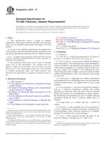
13.1 Shear Tool—A shear test fixture of the sliding type
which is so constructed that the specimen faces are firmly
supported between the stationary and movable blocks to
minimize peel effects. Suitable forms of shear tools are shown
in Figs. 3 and 4, depending on specimen type.
13.2 Testing Machine—See 6.2.
14. Test Specimen
14.1 The test specimens shall be either three-ply or five-ply
construction as shown in Figs. 5 and 6. The five-ply construc4
F521 − 16
1. Three-ply shear test specimen.
2. Female steel housing.
3. Male steel housing.
4. Loading bar (hardened steel).
5. Shim (same thickness as the interlayer).
6. Bolts.
FIG. 3 Three-Ply Shear Test Fixture
TEST METHOD C—CREEP RUPTURE
configurations such as bus bars, separator films, or coated
substrates and symmetric or asymmetric loading conditions.
18. Summary of Test Method
19.2 The test is generally not suitable for quality control
acceptance testing due to the extended time periods required to
obtain results.
18.1 The bond is subjected to a specified duration of load
application under a variety of environmental conditions. The
time to failure or mode of failure, with a given load, is
determined.
20. Apparatus
20.1 Metal Blocks—See 6.1.
19. Significance and Use
20.2 Testing Machine—A tension testing machine with a
constant load setting and a load indicator is suitable for
performing this testing. This type of loading affords a wide
range of applied loads, but due to the time-consuming nature of
19.1 Data from creep tests are of considerable importance in
predicting the performance of materials with variations of
design or interlayer materials. Variations include elevated or
low-temperature testing, incorporation of specific edge design
5
F521 − 16
1. Five-ply shear test specimens.
2. Steel housing.
3. Shim (same thickness as the interlayer).
4. Steel spacer.
5. Loading bar (hardened steel).
6. Bolts.
FIG. 4 Five-Ply Shear Test Fixture
22. Preparation of Apparatus
the test, limits the number of specimens that can be tested
within a period of time. The preferred testing machine is either
a commercial creep machine, or a weighted lever mounted on
a steel frame (see Fig. 7). It is possible to construct test systems
with several stations and a variation of loads by appropriately
positioning a slotted lead weight along the loading lever arm.
22.1 Prepare assembly in accordance with Section 8. If
eccentric loading is desired, prepare assembly in accordance
with Note 3 and Fig. 8.
NOTE 3—In reference to Fig. 8, the specimen shall be mounted
concentrically (solid lines) or eccentrically (dotted lines) according to the
loading area. Instead of the eccentrically mounted specimen, the holes in
the “T” block are moved on a horizontal centerline toward each edge of
the “T” block to produce an eccentric load when the specimen is
concentrically mounted. Variations of the specimen such as separators or
inserts in the interlayer are evaluated by this test method.
4
20.3 Adhesive—Any suitable adhesive.
21. Test Specimen
21.1 See Section 7.
6
F521 − 16
1. Face plies.
2. Interlayer.
FIG. 5 Three-Ply Shear Test Specimen
occur. If failure does occur between adhesive and metal,
discard the test and test another specimen.
25. Report
25.1 The report shall include the following:
25.1.1 Complete identification of the laminate tested, including type or grade of substrate and interlayer, thickness of
each component, manufacturing history, supplier, and so forth,
25.1.2 The block adhesive used,
25.1.3 The total load applied,
25.1.4 The preconditioning data,
25.1.5 The testing environment (temperature and humidity),
25.1.6 The unit stress in pascals (or pounds-force per square
inch),
25.1.7 Time to failure or strain measurement, or both, up to
failure, and
25.1.8 Failure mode.
1. Face plies.
2. Center ply.
3. Interlayer.
FIG. 6 Five-Ply Shear Test Specimen
TEST METHOD D—THERMAL EXPOSURE
26. Summary of Test Method
23. Conditioning
23.1 Condition test specimens for creep testing to obtain
consistent moisture content and temperature. Unless otherwise
specified, condition specimens in accordance with Section 9,
with conditions remaining constant during the test.
26.1 The bond is subjected to extreme temperature changes
(thermal shock). This usually refers to low temperatures since
most multilayer fabrication is done at elevated temperatures.
The resistance of the transparency to cracking, spalling, or
delamination (thermal exposure resistance) is determined.
24. Procedure
27. Apparatus
24.1 When the adhesive has cured, insert the specimen
assembly in the tension machine or test frame and apply the
specified dead-weight load. Record time at application of the
load, at initiation of failure, and at complete failure. Initiation
is often indicated by the appearance of a small delamination,
void, or bubble. This void or bubble is observed through the
polished sides of the specimen.
27.1 Suitable cooling and heating apparatus shall be used to
effect the desired rate of change of temperature. Cooling is
usually accomplished by refrigeration. Heating methods include a circulating air oven, or by built-in heaters on the
transparency.
24.2 If the specimen does not fail after the specified time
interval, remove the load from the test assembly.
28.1 Because thermal expansion stresses are related to
specimen size, the sample shall be the full-size transparency,
unless otherwise agreed upon between the supplier and the
user.
28. Test Specimen
24.3 For testing the material specified, this test method is so
designed that failure between the adhesive and metal shall not
7
F521 − 16
FIG. 7 Lever Loading Frame for Dead Weight Specimen
FIG. 8 Creep Test Specimen
8
F521 − 16
29. Procedure
29.1 Rates of heating and cooling vary with each usage.
Therefore, the exact procedure to be used to determine the
thermal shock resistance shall be as agreed upon between the
supplier and the user. Some guidelines which shall be considered are:
29.2 Mechanically restraining the part so as not to relieve
stresses or break a component by bending.
29.3 Soaking the part at the lowest soak temperature anticipated in service for a time necessary to reach steady state
(thickness dependent, usually less than 4 h).
29.4 Application of full aircraft voltage to the anti-ice
coating until control temperature is achieved. Sometimes a
ramp warm-up feature is included in the controller function,
which is duplicated in the test. In the event an oven is used, the
test part temperature at insertion and the rate of rise shall be as
agreed upon between the supplier and the user.
30.1.2 Complete description of apparatus, set-up method of
measurement, temperature, tolerances, and so forth,
30.1.3 Method of exposure to temperature extreme (including thermal profiles and number of exposures),
30.1.4 Time of failure (if any), and
30.1.5 Description of failure mode.
31. Precision and Bias
31.1 Precision—The task force responsible for this test
method is planning to initiate an interlaboratory test to obtain
data for this precision section. Upon completion this test
method will be submitted for ballot with the new precision
section. Interested parties are encouraged to contact the task
force chairman through ASTM headquarters to obtain the latest
status on this endeavor.
31.2 Bias—Bias cannot be evaluated as there are no absolute or accepted standards for the properties measured.
30. Report
30.1 The report shall include the following:
30.1.1 Complete identification of the laminate tested, including type or grade of substrate and interlayer, thickness of
each component, manufacturing history, supplier, and so forth,
32. Keywords
32.1 adhesion; bond integrity; bond strength; interlayer;
shear strength; tensile strength; transparent laminates
ASTM International takes no position respecting the validity of any patent rights asserted in connection with any item mentioned
in this standard. Users of this standard are expressly advised that determination of the validity of any such patent rights, and the risk
of infringement of such rights, are entirely their own responsibility.
This standard is subject to revision at any time by the responsible technical committee and must be reviewed every five years and
if not revised, either reapproved or withdrawn. Your comments are invited either for revision of this standard or for additional standards
and should be addressed to ASTM International Headquarters. Your comments will receive careful consideration at a meeting of the
responsible technical committee, which you may attend. If you feel that your comments have not received a fair hearing you should
make your views known to the ASTM Committee on Standards, at the address shown below.
This standard is copyrighted by ASTM International, 100 Barr Harbor Drive, PO Box C700, West Conshohocken, PA 19428-2959,
United States. Individual reprints (single or multiple copies) of this standard may be obtained by contacting ASTM at the above
address or at 610-832-9585 (phone), 610-832-9555 (fax), or (e-mail); or through the ASTM website
(www.astm.org). Permission rights to photocopy the standard may also be secured from the Copyright Clearance Center, 222
Rosewood Drive, Danvers, MA 01923, Tel: (978) 646-2600; />
9