Astm f 409 17
Bạn đang xem bản rút gọn của tài liệu. Xem và tải ngay bản đầy đủ của tài liệu tại đây (485.14 KB, 16 trang )
This international standard was developed in accordance with internationally recognized principles on standardization established in the Decision on Principles for the
Development of International Standards, Guides and Recommendations issued by the World Trade Organization Technical Barriers to Trade (TBT) Committee.
Designation: F409 − 17
An American National Standard
Standard Specification for
Thermoplastic Accessible and Replaceable Plastic Tube and
Tubular Fittings1
This standard is issued under the fixed designation F409; the number immediately following the designation indicates the year of original
adoption or, in the case of revision, the year of last revision. A number in parentheses indicates the year of last reapproval. A superscript
epsilon (´) indicates an editorial change since the last revision or reapproval.
This standard has been approved for use by agencies of the U.S. Department of Defense.
1. Scope*
2. Referenced Documents
2.1 ASTM Standards:2
D618 Practice for Conditioning Plastics for Testing
D1600 Terminology for Abbreviated Terms Relating to Plastics
D1784 Specification for Rigid Poly(Vinyl Chloride) (PVC)
Compounds and Chlorinated Poly(Vinyl Chloride)
(CPVC) Compounds
D2122 Test Method for Determining Dimensions of Thermoplastic Pipe and Fittings
D2235 Specification for Solvent Cement for AcrylonitrileButadiene-Styrene (ABS) Plastic Pipe and Fittings
D2564 Specification for Solvent Cements for Poly(Vinyl
Chloride) (PVC) Plastic Piping Systems
D2657 Practice for Heat Fusion Joining of Polyolefin Pipe
and Fittings
D2661 Specification for Acrylonitrile-Butadiene-Styrene
(ABS) Schedule 40 Plastic Drain, Waste, and Vent Pipe
and Fittings
D2665 Specification for Poly(Vinyl Chloride) (PVC) Plastic
Drain, Waste, and Vent Pipe and Fittings
D3965 Classification System and Basis for Specifications for
Rigid Acrylonitrile-Butadiene-Styrene (ABS) Materials
for Pipe and Fittings
D4101 Specification for Polypropylene Injection and Extrusion Materials
F402 Practice for Safe Handling of Solvent Cements,
Primers, and Cleaners Used for Joining Thermoplastic
Pipe and Fittings
F412 Terminology Relating to Plastic Piping Systems
F1498 Specification for Taper Pipe Threads 60° for Thermoplastic Pipe and Fittings
2.2 Federal Standard:
Fed. Std. No. 123 Marking for Shipment (Civil Agencies)3
1.1 This specification covers requirements and test methods
for materials, dimensions and tolerances, hydrostatic pressure,
joint integrity, and solvent cement for thermoplastic tube and
fittings for accessible and replaceable domestic waste connections. Marking requirements are also included. Thermoplastic
that does not meet the material requirements specified in
Section 5 is excluded.
1.2 The text of this specification references notes, footnotes,
and appendixes which provide explanatory material. These
notes and footnotes (excluding those in tables and figures) shall
not be considered as requirements of the specification.
1.3 Units—The values stated in inch-pound units are to be
regarded as standard. The values given in parentheses are
mathematical conversions to SI units that are provided for
information only and are not considered standard.
1.4 The following safety hazards caveat pertains only to the
test methods portion, Section 8, of this specification: This
standard does not purport to address all of the safety concerns,
if any, associated with its use. It is the responsibility of the user
of this standard to establish appropriate safety and health
practices and determine the applicability of regulatory limitations prior to use.
1.5 This international standard was developed in accordance with internationally recognized principles on standardization established in the Decision on Principles for the
Development of International Standards, Guides and Recommendations issued by the World Trade Organization Technical
Barriers to Trade (TBT) Committee.
2
For referenced ASTM standards, visit the ASTM website, www.astm.org, or
contact ASTM Customer Service at For Annual Book of ASTM
Standards volume information, refer to the standard’s Document Summary page on
the ASTM website.
3
Available from DLA Document Services, Building 4/D, 700 Robbins Ave.,
Philadelphia, PA 19111-5094, .
1
This specification is under the jurisdiction of ASTM Committee F17 on Plastic
Piping Systems and is the direct responsibility of Subcommittee F17.63 on DWV.
Current edition approved April 1, 2017. Published May 2017. Originally
approved in 1975. Last previous edition approved in 2012 as F409 – 12. DOI:
10.1520/F0409-17.
*A Summary of Changes section appears at the end of this standard
Copyright © ASTM International, 100 Barr Harbor Drive, PO Box C700, West Conshohocken, PA 19428-2959. United States
1
F409 − 17
TABLE 1 Dimensions and Tolerances for Outside Diameters and Thickness of Plastic Tube
Nominal Tube Size
Average
in.
1 1⁄ 4
1 1⁄ 2
in. (mm)
1.250 (31.75)
1.500 (38.10)
Outside Diameter
Tolerance on Average
in. (mm)
±0.005 (±0.127)
±0.005 (±0.127)
Out-of-Roundness
(maximum minus minimum)
in. (mm)
0.020 (0.51)
0.020 (0.51)
Wall Thickness
Minimum
in. (mm)
0.062 (1.575)
0.062 (1.575)
5.4 Solvent Cement—The ABS solvent cement shall meet
the requirements of Specification D2235. The PVC solvent
cement shall meet the requirements of Specification D2564. No
solvent cement or adhesive joining of propylene plastic (PP) is
permissible.
2.3 Military Standard:
MIL-STD-129 Marking for Shipment and Storage3
2.4 ASME Standard:
B1.20.1 Pipe Threads, General Purpose (Inch)4
3. Terminology
6. Mechanical Connections
3.1 Definitions—Definitions are in accordance with Terminology F412, and abbreviations are in accordance with Terminology D1600, unless otherwise specified.
6.1 Compression or threaded connections shall incorporate
American National Straight Pipe Thread, Mechanical Joints for
Fixtures (NPSM). The thread form shall be the form of
American National Straight Pipe Thread and the dimensions
shall be in accordance with ASME B1.20.1 (NPSM). All
threads shall have a minimum three-thread engagement for
fittings and plastic nuts.
4. Significance and Use
4.1 The requirements of this specification are intended to
provide accessible and replaceable tube and fittings to convey
domestic waste from fixtures to the drain, waste, and vent
(DWV) system.
6.2 Taper Pipe Threads—For all fittings having taper pipe
threads, threads shall conform to Specification F1498 and be
gaged in accordance with 8.5.
5. Materials and Manufacture
6.3 Straight Pipe Threads (NPSM)—For all fittings having
straight pipe threads, threads shall conform to ASME B1.20.1
(NPSM) and be gaged in accordance with 8.6.
5.1 Tube—The tube shall be made of one of the following
materials:
5.1.1 Virgin acrylonitrile-butadiene-styrene (ABS) plastic
which shall meet the requirements of Specification D3965, Cell
Classification 4-2-2-2-2.
5.1.2 Virgin poly(vinyl chloride) (PVC) plastic which shall
meet the requirements for 12454 materials in accordance with
Specification D1784, or
5.1.3 Virgin polypropylene plastic which shall meet the
requirements of Specification D4101, Cell Classification
PP0110B55140 and PP0105G20A33350.
6.4 All tube and fittings made from propylene plastic shall
be assembled by either mechanical connections or by heat
fusion, in accordance with Practice D2657.
7. Requirements
7.1 General—The tube and fittings shall be homogeneous
throughout and free of visible cracks, holes, foreign inclusions,
or other injurious defects. They shall be as uniform as
commercially practicable in color, opacity, density, and other
physical properties.
5.2 Fittings and Mechanical Joint Components—The fittings and components of mechanical joints shall be comprised
of one or more of the following materials:
5.2.1 Virgin ABS plastic which shall meet the requirements
of Specification D3965, Cell Classification 2-0-2-1-1.
5.2.2 Virgin PVC plastics which shall meet the requirements
of 12454 materials as defined in Specification D1784, or
5.2.3 Virgin polypropylene plastic which shall meet the
requirements of Specification D4101, Cell Classification
PP0110B55140, and PP0105G20A33350.
7.2 Dimensions and Tolerances:
7.2.1 Tube:
7.2.1.1 Tube Dimensions—The tube dimensions shall meet
the requirements given in Table 1 when measured in accordance with Test Method D2122.
7.2.1.2 Tube Length—The tolerance on tube lengths is 61⁄8
in. (63 mm).
7.2.2 Fittings:
7.2.2.1 Fitting Dimensions—The dimensions of fittings
shall meet the requirements of Table 2 when measured in
accordance with Test Method D2122.
7.2.2.2 Fitting Laying Length Dimensions—The laying
lengths and other critical dimensions of fittings are shown in
Tables 3-13.
7.2.2.3 Where applicable for assembly, refer to Table A1.1
in Specification D2661, ABS Schedule 40 Fittings.
7.2.2.4 Where applicable for assembly, refer to Table 1 in
Specification D2665, PVC Schedule 40 Fittings.
5.3 Rework Material—The manufacturers shall use only
their own clean rework tube and fitting material and the tube or
fittings produced shall meet all the requirements of this
specification. The different types of material shall not be
mixed.
4
Available from American Society of Mechanical Engineers (ASME), ASME
International Headquarters, Three Park Ave., New York, NY 10016-5990, http://
www.asme.org.
2
F409 − 17
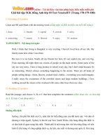
TABLE 2 Dimensions and Tolerances for Plastic Tubular Fittings
NOTE 1—Chamfer or flat, optional.
NOTE 2—Radius or 45° chamfer, optional.
NOTE 3—Radius or chamfer, optional.
Nominal Tube Size
Thread
in.
in.
1 1 ⁄4
1 1 ⁄2
FB
Minimum
in. (mm)
0.062 (1.58)
0.062 (1.58)
11⁄4- 111⁄2 NPSM
11⁄2- 111⁄2 NPSM
S
Minimum
in. (mm)
17⁄64 (6.75)
17⁄64 (6.75)
AA
±0.005 in.
(±0.127 mm)
1.265 (32.13)
1.515 (38.48)
X
±0.005 in.
(±0.127 mm)
1.250 (31.75)
1.500 (38.10)
BA
±0.005 in.
(±0.127 mm)
1.250 (31.75)
1.500 (38.10)
AB
Minimum
in. (mm)
1.258 (31.95)
1.508 (38.30)
C1
Minimum
in. (mm)
11⁄16 (17.46)
11⁄16 (17.46)
EX
±0.010 in.
(±0.254 mm)
0.066 (1.68)
0.066 (1.68)
EB
Minimum
in. (mm)
0.062 (1.58)
0.062 (1.58)
C2
Minimum
in. (mm)
13⁄8 (34.9)
2 (50.8)
BD
Minimum
in. (mm)
0.015 (0.38)
0.015 (0.38)
Maximum
in. (mm)
0.070 (1.78)
0.070 (1.78)
A
Average diameter, the maximum plus minimum diameter divided by 2. The permissible deviation of the diameter from the measured average, often called
out-of-roundness, is +0.010 to −0.010 in. (+0.254 to −0.254 mm).
B
The wall thickness is a minimum value except that a ±10 % variation resulting from core shift is allowable. In such a case, the average of the two opposite wall thicknesses
shall equal or exceed the value shown in the table.
7.4 Axial Stress—Threaded connections shall withstand a
minimum axial load of 50 lbf (220 N) when tested in
accordance with 8.4.
7.3 Hydrostatic Pressure—Tube, fittings, and assemblies
shall withstand a hydrostatic pressure of 25 psi (170 kPa) when
tested in accordance with 8.3.
3
F409 − 17
TABLE 3 FittingsA
NOTE 1—Baffle optional.
NOTE 2—See Table 2 for solvent cement or slip socket hub dimensions.
Nominal
Tube Size
in.
1 1⁄ 2
A
B
G
⁄
13 16
N
J
in. (mm)
⁄ (20.6)
(20.6)
13 16
⁄
1 16
(1.6)B
All dimensions are minimum.
See Table 2.
8. Test Methods
listed in ASME B1.20.1 (NPSM).
8.1 Sampling—Take at random a sample of the tube, fittings,
or assemblies from each lot or shipment that is sufficient to
determine conformance with this specification.
9. Retest and Rejection
9.1 If the results of any test(s) do not meet the requirements
of this specification, the test(s) shall be conducted again only
by agreement between the purchaser and seller. Under such
agreement, minimum requirements shall not be lowered,
changed, or modified, nor shall specification limits be changed.
If upon request, failure occurs, the quantity of product represented by the test(s) does not meet the requirements of this
specification.
8.2 Conditioning—Unless otherwise specified, condition the
specimens prior to test at 70 to 77°F (23 6 2°C) and 50 6 5 %
relative humidity for not less than 40 h in accordance with
Procedure A of Practice D618 for those tests where conditioning is required and in all cases of disagreement.
8.3 Hydrostatic Pressure—Subject the tube and fittings, as
an assembly, to an internal hydrostatic pressure of 25 psi (170
kPa) for 1 h. The tube, fittings, and joints shall show no
evidence of leaking.
10. Product Marking
10.1 Tube—The tube shall be marked in letters not less than
⁄ in. (3 mm) high in a contrasting color and shall at least
consist of the nominal size, manufacturer’s name or trademark,
and “ABS Tubular F409,” “PVC Tubular F409,” or “PP
Tubular F409” at intervals of not greater than 2 ft (610 mm).
18
8.4 Axial Stress—Mount threaded connections in a tensiontesting machine to apply an axial load. Crosshead speed shall
be 0.20 to 0.25 in. (5.0 to 6.3 mm)/min. The connection shall
show no evidence of cracking or separation at the minimum
load specified in 7.4.
10.2 Fittings—All fittings shall be marked on the body or
hub on both sides. The marking shall consist, at least, of the
manufacturer’s name or trademark, the size, and “ABS Tubular
F409,” “PVC Tubular F409,” or “P Tubular F409.”
8.5 Taper Pipe Threads—All taper pipe threads shall be
gaged in accordance with Specification F1498.
8.6 Straight Pipe Threads (NPSM)—For all fittings having
straight pipe threads, threads shall be gaged in accordance with
ASME B1.20.1 (NPSM).
10.3 All baffle tees and such fittings as so required shall be
marked with arrows indicating the direction of flow when
correctly installed.
NOTE 1—Some threads listed in Table 6, Table 9, and Table 12 are not
4
F409 − 17
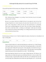
TABLE 4 End Outlet Continuous Waste
NOTE 1—Radius optional.
NOTE 2—Baffle optional.
NOTE 3—Arm shall either be one-piece construction or assembled. If assembled, socket shall conform to Table 2.
NOTE 4—Shall be swivel nut, slip nut, or slip socket connection (shown in Table 5).
NOTE 5—Dishwasher branch optional.
NOTE 6—See Table 6.
NOTE 7—See Table 2.
L
Minimum
in. (mm)
6 (152.4)
HJ
Minimum
in. (mm)
11⁄2 (38.1)
GG
Adjustable in four sizes, in. (mm)
12 (305)
16 (406)
21 (533)
25 (635)
11. Quality Assurance
12. Keywords
11.1 When the product is marked with this designation,
F409, the manufacturer affirms that the product was
manufactured, inspected, sampled, and tested in accordance
with this specification and has been found to meet the
require-ments of this specification.
12.1 ABS; cellular; DWV; fittings; pipe; plastic; Schedule
40; thermoplastic
5
F409 − 17
TABLE 5 Center Outlet Continuous Waste
NOTE 1—See Table 2.
NOTE 2—Radius optional.
NOTE 3—Baffle optional.
NOTE 4—Arm shall be either one-piece construction or assembled. If assembled, socket shall conform to Table 2.
NOTE 5—Shall also be swivel connection as shown in Table 4.
H
Minimum
in. (mm)
11⁄2 (38.1)
L
Minimum
in. (mm)
6 (152.4)
GG
Adjustable in four sizes, in. (mm)
12 (305)
16 (406)
6
21 (533)
25 (635)
F409 − 17
TABLE 6 Dishwasher Branch TailpieceA
NOTE 1—May be swivel or slip connect construction.
NOTE 2—Baffle optional.
NOTE 3—See Table 2.
NOTE 4—See footnote below.B
H
P
in. (mm)
in. (mm)
11⁄4 (31.8)
A
B
C
⁄ (12.7)
12
S
Minimum
in. (mm)
1⁄4 (6.4)
Z
LJC
in. (mm)
in. (mm)
⁄ (15.9) or 7⁄8 (22.2)
4 (102) to 24 (610)
58
All fractional dimensions are minimum.
Threads not listed in ASME B1.20.1 (NPSM).
Lengths shall be agreed upon between the purchaser and the manufacturer.
7
XN
in. (mm)
⁄ (15.9) or 7⁄8 (22.2)
58
F409 − 17
TABLE 7 Extension Tubes and Tail Pieces
NOTE 1—Bondable, belled, or two-piece bondable construction acceptable.
NOTE 2—See Table 2.
NOTE 3—Shall be swivel nut, slip nut, (with flanged tailpiece), or slip socket connection. See Table 8.
F, min
L, min
in. (mm)
in. (mm)
0.062 (1.58)
A
0.75 (19.1)
Lengths shall be agreed upon between the purchaser and the manufacturer. Tubes shall be single- or double-ended.
8
A
F409 − 17
TABLE 8 Swivel Nut and Slip Nut
NOTE 1—Chamfer or radius optional.
NOTE 2—Wing nut design optional.
Size
Thread
in.
in.
1 1⁄4
1 1⁄2
1 1 ⁄ 2 x 1 1 ⁄4
11⁄4- 111⁄2 NPSM
11⁄2- 111⁄2 NPSM
11⁄2- 111⁄2 NPSM
E
in. (mm)
min
0.09 (2.3)
0.09 (2.3)
0.09 (2.3)
L
in. (mm)
min
5⁄8 (15.9)
5⁄8 (15.9)
5⁄8 (15.9)
DJA
in. (mm)
DNA
in. (mm)
max
min
1.665 (42.29)
1.580 (40.13)
max
1.390 (35.31)
1.655 (42.04)
1.390 (35.31)
min
1.260 (32.00)
1.525 (38.74)
1.260 (32.00)
FJ
in. (mm)
min
0.09 (2.3)
FN
in. (mm)
min
1⁄8 (3.2)
1⁄8 (3.2)
1⁄8 (3.2)
A
The part diameter shall be within this dimensional range. The out-of-roundness tolerance from the average measured diameter is +0.010 to –0.010 in. (+0.254 to –0.254
mm).
9
F409 − 17
TABLE 9 DrainsA
NOTE 1—Metal flanges or inserts shall be molded or crimped in accordance with the manufacturer’s specifications.
A
C
E
in. (mm)
min
in. (mm)
min
15⁄16 (33.3)
0.062 (1.57)
M1
in. (mm)
0.062
(±1.58)
13
2 ⁄16 (71.4)
M2
in. (mm)
0.062
(±1.58)
1
2 ⁄8 (54.0)
M3
in. (mm)
0.062
(±1.58)
7
4 ⁄16 (112.7)
Minimum wall thickness 0.062 (1.58).
B
Threads not listed in ASME B1.20.1 (NPSM) .
10
L1
L2
L3
S
in. (mm)
min
in. (mm)
min
in. (mm)
min
in. (mm)
min
11⁄8 (28.6)
5 (127.0)
2 (50.8)
⁄
7 16
(11.1)
F409 − 17
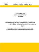
TABLE 10 P TrapsA
NOTE 1—Dimensions shall be suitable for solvent welding to Schedule 40 DWV or threads shall be in accordance with 6.2.
NOTE 2—Radius optional.
NOTE 3—Ribs optional.
NOTE 4—Ground joint construction optional.
NOTE 5—Single-radius or multi-radius traps shall provide a 2-in. minimum water seal.
NOTE 6—See Table 2 for P-trap inlet slip socket and spigot end dimensions.
NOTE 7—Socket dimensions suitable for solvent welding to 11 ⁄4 or 11⁄2-in. tubular trap arm as required.
NOTE 8—Threads and socket dimensions for compression joint connection optional. Threads to be either 11⁄4-111⁄2 NPSM or 11⁄2 -111⁄2 NPSM as
required.
A
Size
C
E
in.
in. (mm)
in. (mm)
1 1⁄ 4
1 1⁄ 2
13⁄8 (34.9)
2 (50.8)
0.062 (1.57)
0.062 (1.57)
X
in. (mm)
±0.010 (±0.254)
1.250 (31.75)
1.500 (38.10)
CM
GJ
GN
GGN
L1
L2
in. (mm)
in. (mm)
in. (mm)
in. (mm)
in. (mm)
in. (mm)
⁄ (6.4)
⁄ (6.4)
91⁄4 (235.0)
11 (279.4)
33⁄8 (87.5)
4 (101.6)
3 (76.2)
31⁄4 (82.6)
14
14
All dimensions are minimum unless otherwise indicated.
11
⁄
⁄
13 16
13 16
(20.6)
(20.6)
11⁄2 (38.1)
11⁄2 (38.1)
F409 − 17
TABLE 11 Lavatory Pop-up Drain
NOTE 1—Plastic or metal flanges shall be secured in accordance with the manufacturer’s specifications.
NOTE 2—Overflow openings are optional, when used they must have a combined area of at least 1 in.2 (654.2 mm2).
NOTE 3—See Table 2.
NOTE 4—Stop movement shall be 0 to 0.50 in. (0 to 12.7 mm) min.
NOTE 5—Must be adjustable between 0 to 2 in. (0 to 50.8 mm), or 11⁄2 to 2 in. (38.1 to 50.8 mm) when optional overflow is used.
NOTE 6—Pop-up shall operate at a minimum adjustable range from 41⁄8 to 7 in. (104.8 to 177.8 mm).
min
H
max
in. (mm)
L
min
in. (mm)
M
in. (mm)
0.062 (1.57)
33⁄8 (85.7)
53⁄8 (137)
81⁄2 (215.9)
21⁄8 (54.0)
12
F409 − 17
TABLE 12 Bath DrainA
NOTE 1—Tee seat-, pop-up-, and rubber stopper-type models are allowed.
NOTE 2—3⁄4 IPS condensate connection permissible on overflow.
NOTE 3—See Table 2.
NOTE 4—Slip joint or one-piece construction optional.
G
in. (mm)
11⁄8 (28.6)
A
B
N
in. (mm)
⁄
3 32
(2.4)
GG
in. (mm)
LJ
in. (mm)
LN
in. (mm)
MJ
in. (mm)
MN
in. (mm)
THR’D
in.
6 (152.4)
107⁄8 (276.2)
4 (101.6)
223⁄32 (69.1)
3 (76.2)
11⁄2- 111⁄2 NPSM
15⁄8- 16 NPSMB
All dimensions are minimum unless otherwise specified.
Threads not listed in ASME B1.20.1 (NPSM).
13
F409 − 17
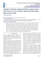
TABLE 13 Transition Adapter
L
in. (mm)
2.070 (52.58)
J
in. (mm)
0.380 (9.65)
LM
in. (mm)
0.550 (13.97)
LH
in. (mm)
0.410 (10.41)
G
in. (mm)
0.807 (20.50), min
N
in. (mm)
0.452 (10.80)
A
in. (mm)
0.300 (7.62)
C
in. (mm)
0.150 (3.81)
JG
in. (mm)
0.547 (13.89)
E
in. (mm)
0.100 (2.54), min
GT
in. (mm)
1.272 (32.31), min
S
in. (mm)
0.455 (11.56)
GB
in. (mm)
1.760 (44.70), min
NA
in. (mm)
0.507 (12.88)
JA
in. (mm)
0.255 (6.48)
GA
in. (mm)
0.424 (10.77)
EA
in. (mm)
0.050 (1.27), min
ZA
in. (mm)
0.308 (7.82)
Z
in. (mm)
0.465 (11.81)
B
in. (mm)
0.510 (12.95)
SUPPLEMENTARY REQUIREMENTS
GOVERNMENT/MILITARY PROCUREMENT
These requirements apply only to federal/military procurement, not domestic sales or transfers.
S2.1 Packaging—Unless otherwise specified in the
contract, the materials shall be packaged in accordance with
the supplier’s standard practice in a manner ensuring arrival at
destination in satisfactory condition and which will be acceptable to the carrier at lowest rates. Containers and packing shall
comply with Uniform Freight Classification rules or National
Freight Classification rules.
S1. Responsibility for Inspection—Unless otherwise specified in the contract or purchase order, the producer is responsible for the performance of all inspection and test requirements specified herein. The producer may use his own or any
other suitable facilities for the performance of the inspection
and test requirements specified herein, unless the purchaser
disapproves. The purchaser shall have the right to perform any
of the inspections and tests set forth in this specification where
such inspections are deemed necessary to ensure that material
conforms to prescribed requirements.
S2.2 Marking—Marking for shipment shall be in accordance with Fed. Std. No. 123 for civil agencies and MIL-STD129 for military agencies.
NOTE S1.1—In U.S. federal contracts, the contractor is responsible for
inspection.
NOTE S2.1—The inclusion of U.S. Government procurement requirements should not be construed as an indication that the U.S. Government
uses or endorses the products described in this specification.
S2. Packaging and Marking for U.S. Government Procurement:
14
F409 − 17
APPENDIX
(Nonmandatory Information)
X1. STORAGE AND INSTALLATION PROCEDURES FOR PLASTIC TUBE AND TUBULAR FITTINGS
completely covering the pipe joining surfaces only. Heavy or
excessive applications of cement may become an obstruction
inside of the piping. Quickly apply a heavy even coat of
cement to the outside of the pipe. Make sure that the coated
distance on the pipe is equal to the depth of the fitting socket.
X1.1 Storage—Do not store tubing and fittings in direct
sunlight for long periods. Store tubing in such a manner as to
prevent sagging or bending.
X1.2 Visibility of Marking—Position tubing and fittings so
that identifying markings are readily visible to inspection when
installed.
X1.5.5 Assembly—Make the joint as quickly as possible
after application of the cement and before the cement dries.
Insert the pipe into the fitting socket, turning the pipe slightly
to ensure even distribution of cement. Make sure that the pipe
is inserted to the full depth of the socket. Remove excess
solvent cement from the exterior of the joint with a clean, dry
cloth. Reasonable handling of the assembly is permissible
within 2 min after joining. Do not attempt to disturb the
pipe-fitting joint until after the cement has set; damage to the
joint and loss of fit may result. Should the cement dry partially
before the joint is made up, reapply cement before assembling.
Allow 15 min for the joint to develop good handling strength.
X1.3 Solvent Cement—Use solvent cements meeting the
requirements of Specification D2235 for ABS tube and fittings.
Poly(vinyl chloride) requires solvent cements meeting the
requirements of Specification D2564. No cement joining of PP
is permissible. Cements should be packaged in containers
suitable for size of pipe being joined. Do not thin the cement.
Discard cement that has thickened. Solvent cements are flammable. Keep away from heat, spark, and open flame. Avoid
prolonged breathing of vapors. Prolonged contact with skin is
harmful. Use with adequate ventilation and avoid contact with
eyes and skin. For further information, see Practice F402.
X1.6 Threaded Connections—Do not cut threads on tubular
pipe. Molded threads are permitted. Only approved thread tape
or thread lubricant specifically intended for use with plastic
pipe should be used. Conventional pipe thread compounds,
putty, linseed oil-based products, and unknown mixtures shall
be avoided.
X1.4 Socket Fit—Tubular pipe and fittings are manufactured to close tolerances. Close tolerances are required to
ensure satisfactory“ interference’’ fit between pipe and fitting
during the solvent cement joining. Use only pipe and fitting
combinations that give interference fits. Pipe loose in the
socket may not properly fuse chemically. The allowable
tolerances ensure a forced fit and when solvent is applied will
readily mate, thus ensuring a chemical fusion equal in strength
to pipe or fitting. Attempting to correct a loose fit after
assembly by additional cement may result in an unsatisfactory
joint.
X1.6.1 Thread Tightness—Where a threaded joint is made,
obtain tightness by maximum hand tightening plus tightening
with a strap wrench not to exceed one full turn.
X1.6.2 Connection to Traps—Connect traps by means of
approved threaded trap adaptors.
X1.6.3 Connection to Non-Plastic Pipe—When connecting
plastic tube to other types of piping, use only approved types of
fittings and adaptors, designed for the specific transition
intended.
X1.5 Joining Technique:
X1.5.1 Cutting the Pipe—Cut the pipe square with saws or
pipe cutters designed specifically for this material; protect pipe
and fittings from serrated holding devices and abrasion.
X1.7 Alignment and Grade—Align all piping system components properly without strain. Do not bend or pull pipe into
position after being solvent welded. The grade of horizontal
drainage and vent piping shall be as specified for other
materials in the applicable code.
X1.5.2 Deburring Pipe—Remove burrs from inside and
outside pipe edges.
X1.5.3 Cleaning Joining Surfaces—Wipe off all dust, dirt,
and moisture from surfaces to be cemented with a clean, dry
rag or paper towel. Remove gloss and any oily film from the
pipe and mating socket with clean steel wool, fine abrasive
paper, chemical cleaner, or primer. In case of conflicting
solvent cementing instructions, the instructions of the cement
manufacturer should be followed.
X1.8 Antifreeze Protection—When necessary protect traps
and fixtures from freezing. Do not use alcohol or petroleum
products. Use only approved plastic pipe antifreeze packaged
for this purpose or one of the following solutions:
X1.8.1 Sixty weight percent of glycerin in water mixed at
23°C (73°F).
X1.5.4 Application of Cement—Use a natural bristle or
nylon brush of adequate size (usually at least 1⁄2 the pipe
diameter) or applicator supplied with the can of cement. First
apply a moderate even coating of cement in the fitting socket
X1.8.2 Twenty-two percent of magnesium chloride in water.
Strong solutions of common table salt (sodium chloride) may
also be used.
15
F409 − 17
SUMMARY OF CHANGES
Committee F17 has identified the location of selected changes to this standard since the last issue (F409 – 12)
that may impact the use of this standard.
(5) Updated URL in footnote 3.
(6) Revised PVC cell class designation in 5.1.2 and 5.2.2.
(7) Spelling corrections in Note 3 of Table 7.
(8) Replaced “Thr’d” with “Thread” in Table 8.
(1) Added Summary of Changes section, including required
note at bottom of first page.
(2) Revised wording of 1.1 for additional clarity.
(3) Revised 1.3 to comply with Form and Style Manual.
(4) Revised designation for ASME B1.20.1 in 2.4, 6.2, 6.3, 8.6,
and Table 6, Table 9, and Table 12.
ASTM International takes no position respecting the validity of any patent rights asserted in connection with any item mentioned
in this standard. Users of this standard are expressly advised that determination of the validity of any such patent rights, and the risk
of infringement of such rights, are entirely their own responsibility.
This standard is subject to revision at any time by the responsible technical committee and must be reviewed every five years and
if not revised, either reapproved or withdrawn. Your comments are invited either for revision of this standard or for additional standards
and should be addressed to ASTM International Headquarters. Your comments will receive careful consideration at a meeting of the
responsible technical committee, which you may attend. If you feel that your comments have not received a fair hearing you should
make your views known to the ASTM Committee on Standards, at the address shown below.
This standard is copyrighted by ASTM International, 100 Barr Harbor Drive, PO Box C700, West Conshohocken, PA 19428-2959,
United States. Individual reprints (single or multiple copies) of this standard may be obtained by contacting ASTM at the above
address or at 610-832-9585 (phone), 610-832-9555 (fax), or (e-mail); or through the ASTM website
(www.astm.org). Permission rights to photocopy the standard may also be secured from the Copyright Clearance Center, 222
Rosewood Drive, Danvers, MA 01923, Tel: (978) 646-2600; />
16