Astm f 450 13
Bạn đang xem bản rút gọn của tài liệu. Xem và tải ngay bản đầy đủ của tài liệu tại đây (214.84 KB, 7 trang )
Designation: F450 − 13
An American National Standard
Standard Test Methods for
Vacuum Cleaner Hose—Durability and Reliability (Plastic)1
This standard is issued under the fixed designation F450; the number immediately following the designation indicates the year of original
adoption or, in the case of revision, the year of last revision. A number in parentheses indicates the year of last reapproval. A superscript
epsilon (´) indicates an editorial change since the last revision or reapproval.
F595 Test Methods for Vacuum Cleaner Hose—Durability
and Reliability (All-Plastic Hose) (Withdrawn 2010)3
1. Scope
1.1 These test methods cover the determination of the effect
of anticipated stresses and strains that vacuum cleaner and
extractor hoses will receive in normal use.
3. Terminology
3.1 Definitions—Refer to Terminology F395.
1.2 These test methods apply to plastic (regular and reinforced) vacuum cleaner and extractor hoses for household use.
4. Significance and Use
1.3 The following tests are included:
Torsional flex
Hot and cold flex with aging
Abrasion, external surfaces
Flex
Pull test on hose fittings with aging
Crush
Stretch ratio
Extractor hoses
4.1 These test methods can be used by buyers of vacuum
cleaner hose to specify the test criteria the hose must meet to
be acceptable for their purposes.
Section
6
7
8
9
10
11
12
13
5. Sampling
5.1 The sample size shall be one that is mutually agreed
upon between the hose manufacturer and the vacuum cleaner
manufacturer.
1.4 These test methods are individual tests as agreed upon
between the hose and vacuum manufacturer.
TEST METHODS
1.5 The values stated in inch-pound units are to be regarded
as standard. The values given in parentheses are mathematical
conversions to SI units that are provided for information only
and are not considered standard.
1.6 This standard does not purport to address all of the
safety concerns, if any, associated with its use. It is the
responsibility of the user of this standard to establish appropriate safety and health practices and determine the applicability of regulatory limitations prior to use.
6. Torsional Flex Test
6.1 Scope—This test method covers the determination of the
adhesion of the reinforcement wire coating to the hose jacket,
the jacket strength, and the strength of the reinforcement wire
for plastic hose with inside diameter from 1 to 2 in. (25 to 51
mm).
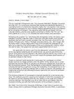
6.2 Apparatus—The apparatus shown in Fig. 1 is suitable
for this test method with the following provisions:
6.2.1 Means to rotate test mandrel in a horizontal plane at 20
6 1 rpm, both clockwise and counter-clockwise.
6.2.2 Test weight of 48 6 1 oz (1360 6 28 g) with provision
to attach to sample hose.
6.2.3 Suitable clamp to attach sample hose to mandrel that
retains the hose without causing failure at the clamp during the
test.
6.2.4 Test mandrel with diameter same as inside diameter of
hose with 0.078 in. (2.0 mm) radius at the ends of the mandrel
(see Fig. 1).
6.2.5 Guide for weight to prevent hose sample from swinging during test cycle.
6.2.6 Instrument to measure cycles to failure or to a specified end point.
2. Referenced Documents
2.1 ASTM Standards:2
D638 Test Method for Tensile Properties of Plastics
D695 Test Method for Compressive Properties of Rigid
Plastics
F395 Terminology Relating to Vacuum Cleaners
1
These methods are under the jurisdiction of ASTM Committee F11 on Vacuum
Cleaners and are the direct responsibility of Subcommittee F11.30 on DurabilityReliability.
Current edition approved May 1, 2013. Published June 2013. Originally
approved in 1979. Last previous edition approved in 2009 as F450 – 09. DOI:
10.1520/F0450-13.
2
For referenced ASTM standards, visit the ASTM website, www.astm.org, or
contact ASTM Customer Service at For Annual Book of ASTM
Standards volume information, refer to the standard’s Document Summary page on
the ASTM website.
3
The last approved version of this historical standard is referenced on
www.astm.org.
Copyright © ASTM International, 100 Barr Harbor Drive, PO Box C700, West Conshohocken, PA 19428-2959. United States
1
F450 − 13
FIG. 1 Schematic for Torsional Flex Test
7.5 Procedure:
7.5.1 Bend a specimen in a “U” shape and tie the ends
together at a position 1 in. (25 mm) from the ends as shown in
Fig. 2.
7.5.2 Place the specimen into the oven, which has been
brought to a steady test temperature of 156 6 2°F (69 6 1°C),
and soak the sample for 201⁄2 h.
7.5.3 Remove the specimen from the oven and allow 30 min
for samples to come to ambient temperature in accordance with
7.4.
7.5.4 Next, place the specimen in the cold box, which has
been brought to a steady temperature of 20 6 1°F (−6.7 6
0.5°C) for 2 h.
7.5.5 Remove the specimen from the cold box, untie and
immediately flex it 360°, three times, 1 s per flex, as shown in
Fig. 3.
7.5.6 Failure may be evidenced by a tear or hole that
penetrates the hose jacket to cause air leak, or a collapsed coil
or ply for a lined-type hose, or any combination thereof.
Reinforcement wires that pull away or holes worn in outer
jacket that do not cause air leaks are not determined to be
failures.
7.5.7 Retie the hose in its original position.
7.5.8 Allow 1 h for conditioning as specified in 7.4 before
starting next cycle.
7.5.9 The steps covered in 7.5.1 – 7.5.8 constitute one cycle.
Conduct this complete cycle of tests for four successive days,
then permit the specimens to remain at ambient conditions for
the unused balance of a 7-day period, then repeat until a failure
occurs or until a specified end point is reached, whichever
occurs first.
6.3 Test Specimen—The specimen shall be a length of hose
24 6 1 in. (610 6 25 mm) without fittings.
6.4 Conditioning—Condition the specimens at an ambient
temperature of 68 to 81°F (20 to 27°C) for not less than 1 h
prior to test.
6.5 Procedure:
6.5.1 Conduct the tests at 68 to 81°F (20 to 27°C).
6.5.2 Clamp the specimen to the test hose mandrel as shown
in Fig. 1 and attach a weight to other end of hose sample.
6.5.3 Set measuring instrument at zero or record the initial
reading.
6.5.4 Test half of the specimens by rotating clockwise and
the other half by rotating counter-clockwise at 20 6 1 rpm until
failure or to a specified end point.
6.5.5 Failure may be evidenced by a broken reinforcing
wire, tear, or hole that penetrates the hose jacket, or a collapsed
coil or ply for a lined-type hose, or any combination thereof.
6.5.6 Additionally, breaking or damaging of the conductors,
or an increase of more than 10 % of the conductor resistance,
is considered to be a failure for current-carrying hoses.
7. Hot and Cold Flex Test with Aging
7.1 Scope—This test method covers the determination of the
effect of temperature and flexing upon a hose sample with
inside diameters from 1 to 2 in. (25 to 51 cm).
7.2 Apparatus:
7.2.1 Air-Circulating Oven or Environmental Chamber, to
maintain 156°F (69°C) controlled to 62°F (61°C).
7.2.2 Cold Box—A cold box able to maintain 20°F (−6.7°C)
controlled to 61°F (60.5°C).
7.3 Test Specimen—The specimen shall be a length of hose
in which the length in inches or millimetres shall be determined
as follows:
7.6 Report—The report shall include the following:
7.6.1 Number of cycles to failure or to a specified end point,
whichever occurs first,
7.6.2 Condition of the specimen,
7.6.3 Ambient test temperature,
7.6.4 Description of specimen, and
7.6.5 Number of specimens tested.
11.2 3 inside diameter, in inches12 in.
~ 11.2 3 inside diameter, in millimetres151 mm!
7.4 Conditioning—Condition the specimens at an ambient
temperature of 68 to 81°F (20 to 27°C) for not less than 1 h
prior to test.
2
F450 − 13
8.5.5 Cycle the specimen against the surface of the abrasive
paper until failure of jacket or to a specified end point.
8.5.6 Failure may be evidenced by a tear or hole that
penetrates the hose jacket to cause air leak, or a collapsed coil
or ply for a lined-type hose, or any combination thereof.
Reinforcement wires that pull away or holes worn in outer
jacket that do not cause air leaks are not determined to be
failures.
8.5.7 Additionally, exposure of the bare conductor wire is
considered a failure in a current-carrying hose.
FIG. 2 Hose Position During Heat and Cold Soak
8.6 Report—The report shall include the following:
8.6.1 Number of cycles to failure or to a specified end point,
whichever occurs first,
8.6.2 Description of failure,
8.6.3 Ambient test temperature,
8.6.4 Description of specimen, and
8.6.5 Number of pieces tested.
FIG. 3 Hose Flex Cycle
9. Flex Test
9.1 Scope—This test method covers the determination of the
vacuum cleaner hose resistance to bending under an applied
stress.
8. Abrasion Test of External Surface
8.1 Scope—This test method measures the wear characteristics of a vacuum cleaner hose subjected to an abrasive
surface.
8.2 Apparatus:
8.2.1 Special Abrasion Test Fixture, as described in Fig. 4 to
produce a rate of 20 6 1 cycles/min.
8.2.2 Cylindrical Segment, as described in Fig. 5.
8.2.3 Test Weight, 16 6 1 oz (454 6 3 g) with provision to
attach to the specimen.
8.2.4 Abrasive Paper, wet-dry, 500-grit, for abrasion test
surface.4
8.2.5 Instrument, to measure cycles to failure or to a
specified end point.
8.2.6 Weight Guide, to prevent weight from swinging during
test cycling.
8.2.7 Clamps, suitable for attaching the hose to the mechanism coupling on one end and attaching the weight to the other
end without causing failure of the hose at these clamps.
9.2 Apparatus:
9.2.1 Special Abrasion Test Fixture, as described in 8.2.1
and Fig. 4 except with driving arm rotating at 36 6 1
cycles/min and the cylindrical segment replaced with pulley
(9.2.2).
9.2.2 Pulley, a cold-rolled steel (or similar) grooved pulley
as described in Fig. 6.
9.2.3 Test Weight, 160 6 1 oz (4536 6 28 g) for reinforced
hoses and 80 6 1 oz (2268 6 28 g) for plastic hoses with
provision for attaching to the specimen.
9.2.4 Weight Guide, to prevent weight from swinging during
test cycling.
9.2.5 Instrument, to measure cycles to failure or to a
specified end point.
9.2.6 Clamps, suitable for attaching the hose to the mechanism coupling on one end and attaching the weight to the other
end without causing failure of the hose at these clamps.
8.3 Test Specimen—The specimen shall be a full length
hose, or a length of hose suitable for the test unit.
9.3 Test Specimen—The specimen shall be a full length
hose, or a length of hose suitable for the test unit.
8.4 Conditioning—Condition the specimen at 68 to 81°F (20
to 27°C) ambient temperature for not less than 1 h prior to test.
9.4 Conditioning—Condition the specimen at 68 to 81°F (20
to 27°C) ambient temperature for not less than 1 h prior to test.
8.5 Procedure:
8.5.1 Conduct the tests at 68 to 81°F (20 to 27°C).
8.5.2 Clamp a new sheet of standard wet-dry, 500-grit
abrasive paper to the cylinder.
8.5.3 Clamp the specimen to the mechanism coupling.
Attach the weight and place in the weight guide. The weight
shall be in free suspension throughout the cycle.
8.5.4 Set the measuring instrument to zero or record starting
value.
9.5 Procedure:
9.5.1 Conduct tests at 68 to 81°F (20 to 27°C).
9.5.2 Clamp the specimen to the mechanism coupling.
Attach the weight and place in weight guide. The weight shall
be in free suspension throughout the cycle.
9.5.3 Set the measuring instrument to zero or record the
starting value.
9.5.4 Run the test until failure or until a specified end point
is reached, whichever occurs first.
9.5.5 Failure may be evidenced by a tear or hole that
penetrates the hose jacket to cause air leak, or a collapsed coil
or ply for a lined-type hose, or any combination thereof.
4
Wet-dry, 500-grit, Tri-M-Ite Abrasive Paper, available from 3M Co., St. Paul,
MN, has been found suitable for this purpose.
3
F450 − 13
FIG. 4 Abrasion and Flex Test Fixture (Abrasion Set Up Shown)
FIG. 5 Cylindrical Segment (Abrasion Test)
FIG. 6 Pulley Flex Test Fixture
Reinforcement wires that pull away or holes worn in outer
jacket that do not cause air leaks are not determined to be
failures.
9.5.6 Additionally, breaking or damaging of the conductors,
or an increase of more than 10 % of the conductor resistance,
is considered to be a failure for current-carrying hoses.
4
F450 − 13
10.5.3.4 Repeat the test with slightly decreasing amounts of
force until the greatest force applied to the sample for 1 min
without pulling the fitting from the hose is reached. Note this
value.
10.5.3.5 If the hose failure occurs before either the fitting or
fitting to hose bond, report as hose failure and note the load
applied.
9.6 Report—The report shall include the following:
9.6.1 Number of cycles to failure or specified end point,
whichever occurs first,
9.6.2 Type of failure,
9.6.3 Ambient test temperature,
9.6.4 Description of specimen, and
9.6.5 Number of pieces tested.
10.6 Report—The report shall include the following:
10.6.1 Maximum weight or load supported without failure,
10.6.2 Location of failure,
10.6.3 Ambient test temperature,
10.6.4 Hose and fitting description, and
10.6.5 Number of specimens tested.
10. Pull Test on Hose Fittings with Aging
10.1 Scope—This test method covers the determination of
the ability of the vacuum cleaner hose fitting connection to
withstand maximum forces during use.
10.2 Apparatus:
10.2.1 Oven and Cold Box, as specified in 7.2,
10.2.2 Total Test Weight, in 80 6 0.5-oz (2268 6 14-g)
increments.
10.2.3 Testing Machine (alternative to the dead weight)—A
properly calibrated machine of the constant-rate-of crosshead
movement type meeting the requirements of Test Method D638
(see 10.5.3 for tension method).
11. Crush Test (Relaxed and Stretched)
11.1 Scope—This test method covers the determination of
the resistance to crushing of the hose.
11.2 Apparatus:
11.2.1 Total Dead Weight, in convenient weight increments
to apply a steady, non-impact compression force.
11.2.2 Testing Machine (alternative for the dead weight)—A
properly calibrated compression testing machine of the
constant-rate-of-crosshead movement type meeting the requirements of Test Method D695.
11.2.3 Loading Plates—The load shall be applied to the
specimen through a 21⁄2 in. (63.5 mm) wide plate with 0.062-in.
(1.6-mm) radius edges. Thickness of the plate shall not be less
than 0.50 in. (12.7 mm).
10.3 Test Specimen—The test specimen shall be a 1-ft
(0.3-m) long section from each end of the hose containing the
cleaner attachment fittings, or the hose fittings, or both. Its
length shall conform to the requirements of 10.5.3.1 if the
tensile machine test method is used.
10.4 Conditioning—Prior to test on fittings, age the specimens by performing the following heat/cold soak.
10.4.1 Place the specimen, in straight configuration, in an
air-circulating oven at 156° 6 2°F (69 6 1°C) for 201⁄2 h.
10.4.2 Remove the specimen from the oven and allow 30
min for the specimens to come to equilibrium with ambient
temperature 68 to 81°F (20 to 27°C).
10.4.3 Place the specimen in cold box at 20 6 1°F (−6.7 6
0.5°C) for 2 h.
10.4.4 Remove the specimens from the cold box and allow
1 h for them to return to ambient temperature before conducting the pull test.
11.3 Test Specimen—The specimen shall be a minimum
length hose of 8 in. (203 mm) with force applied in the center
of the specimen. Length applies for both relaxed and stretched
positions.
11.4 Conditioning—Condition the specimen at 68 to 81°F
(20 to 27°C) prior to test for not less than 1 h.
11.5 Procedure:
11.5.1 Conduct tests at 68 to 81°F (20 to 27°C).
11.5.2 Measure the outside diameter of the specimen at the
center.
11.5.3 Dead Weight Method:
11.5.3.1 Locate the hose with its axis parallel to the plane
surface and loading plate (see Fig. 7).
11.5.3.2 Apply the dead test weight to the bearing plate at
the hose center.
11.5.3.3 Apply a non-impact load in convenient dead weight
increments for 30 s which results in a permanent deformation
of 25 % reduction in the original diameter as measured after
allowing a 30-min relaxation period.
11.5.4 Compression Testing Machine Method:
11.5.4.1 Set up compression fixture in testing machine.
11.5.4.2 Locate the hose area to be tested in a plane surface,
then place loading plate with the hose axis parallel to the plate.
11.5.4.3 Apply the load at the rate of 0.50 6 0.2 in. (12.7 6
5.1 mm)/min until 25 % reduction in diameter is reached. Hold
for 30 s. Stop the machine and remove the load. Allow 30 min
for the test specimen to relax before measuring.
11.5.5 The hose may then be restored to its original shape
after final reduction by hand only.
10.5 Procedure:
10.5.1 Conduct the tests at ambient temperature of 68 to
81°F (20 to 27°C).
10.5.2 Dead Weight Method:
10.5.2.1 Clamp the fitting of the specimen to the dead
weight.
10.5.2.2 Holding the hose, lift the weight slowly. Hold off
the floor for 1 min.
10.5.2.3 With dead weight hold 1 min, otherwise pull until
failure with increasing load on the fitting in 80-oz (2268-g)
increments.
10.5.2.4 Test both ends.
10.5.3 Tension Testing Machine Method:
10.5.3.1 Select a specimen length short enough so that the
end treatment is pulled off before the hose stretches the entire
distance of travel of the instrument.
10.5.3.2 Fasten both ends of the hose firmly in the machine.
10.5.3.3 Stretch the sample at the rate of 0.50 6 0.2 in.
(12.7 6 6.1 mm)/min until the hose pulls away from the fitting.
Note the force applied.
5
F450 − 13
FIG. 7 Crush Test Fixture
12.5.3 Attach clamp to within 2 in. of bottom of hose that
will attach to dead weight.
12.5.4 Measure the distance between the 2 inside edges of
the hose clamps with the hose laid straight and in the relaxed
condition (distance T1).
12.5.5 Attach test weight to clamp on bottom of hose.
12.5.6 Holding the top clamp, slowly lift the hose until the
weight is clear from the floor. Hold for 10 s.
12.5.7 Measure distance between the inside edges of the
hose clamps (distance T2).
12.5.8 Stretch ratio = T2/T1.
11.5.6 Calculate the percent reduction in diameter as follows:
Percent reduction in diameter = (original – final minor diameter)/original
diameter.
11.6 Report—The report shall include the following:
11.6.1 Original diameter,
11.6.2 State hose was tested in (relaxed or stretched),
11.6.3 Load applied to produce 25 % permanent reduction,
11.6.4 Load applied and percent reduction in diameter if
25 % permanent reduction could not be obtained,
11.6.5 Percent reduction after restoration by hand,
11.6.6 Ambient test temperature,
11.6.7 Specimen description, and
11.6.8 Number of specimens tested.
12.6 Report—The report shall include the following:
12.6.1 Values of T2, T1, and stretch ratio.
12.6.2 Ambient test temperature.
12.6.3 Hose description.
12.6.4 Number of pieces tested.
12. Stretch Ratio
12.1 Scope—This test method covers the determination of
the stretch ratio of vacuum and extractor hoses under a
prescribed weight.
13. Extractor Hoses
13.1 Scope—This test method covers the pre-conditioning
of the hoses used in wet conditions with extractors. This
pre-conditioning shall be done prior to any of the tests outlined
in Sections 6 – 12.
12.2 Apparatus:
12.2.1 Test Weight, 10 6 0.1 lb.
12.2.2 Clamps, suitable for attaching the hose to the fixture
on one end and attaching the weight to the other end without
causing failure of the hose at these clamps.
12.2.3 Tape Measure.
13.2 Conditioning—Prior to test, age the specimens by
performing the following heat/cold/wet soak:
13.2.1 Place the specimen, in straight configuration, in an
air-circulating oven at 156 6 2°F (69 6 1°C) for 201⁄2 h.
13.2.2 Remove the specimen from the oven and allow 30
min for the specimens to come to equilibrium with ambient
temperature 68 to 81°F (20 to 27°C).
13.2.3 Place the specimen in cold box at 20 6 1°F (6.7 6
0.5°C) for 2 h.
13.2.4 Remove the specimens from the cold box and allow
1 h for them to return to equilibrium with ambient temperature
68 to 81°F (20 to 27°C).
13.2.5 Soak the specimen (inside and out) at 3× concentration of the chemical fluid (68 to 81°F) that will be used in the
wet appliance for a period of 24 h.
13.2.6 Proceed to perform tests from Sections 6 – 12.
12.3 Test Specimen—The test specimen shall be 24 in. in
length (relaxed state).
12.4 Conditioning—Prior to test, age the specimens by
performing the following heat/cold soak.
12.4.1 Place the specimen, in straight configuration, in an
air-circulating oven at 156 6 2°F (69 6 1°C) for 201⁄2 h.
12.4.2 Remove the specimen from the oven and allow 30
min for the specimens to come to equilibrium with ambient
temperature 68 to 81°F (20 to 27°C).
12.4.3 Place the specimen in cold box at 20 6 1°F (6.7 6
0.5°C) for 2 h.
12.4.4 Remove the specimens from the cold box and allow
1 h for them to return to ambient temperature before conducting the test.
12.5 Procedure:
12.5.1 Conduct the tests at ambient temperature of 68 to
81°F (20 to 27°C).
12.5.2 Attach clamp to within 2 in. of top end of hose.
14. Precision and Bias
14.1 Precision—No meaningful precision statement can be
made due to the variability inherent in durability testing.
6
F450 − 13
14.2 Bias—A bias statement cannot be applied to these test
methods as there is no standard reference for comparison.
15. Keywords
15.1 durability; vacuum cleaner hose; vacuum cleaners
ASTM International takes no position respecting the validity of any patent rights asserted in connection with any item mentioned
in this standard. Users of this standard are expressly advised that determination of the validity of any such patent rights, and the risk
of infringement of such rights, are entirely their own responsibility.
This standard is subject to revision at any time by the responsible technical committee and must be reviewed every five years and
if not revised, either reapproved or withdrawn. Your comments are invited either for revision of this standard or for additional standards
and should be addressed to ASTM International Headquarters. Your comments will receive careful consideration at a meeting of the
responsible technical committee, which you may attend. If you feel that your comments have not received a fair hearing you should
make your views known to the ASTM Committee on Standards, at the address shown below.
This standard is copyrighted by ASTM International, 100 Barr Harbor Drive, PO Box C700, West Conshohocken, PA 19428-2959,
United States. Individual reprints (single or multiple copies) of this standard may be obtained by contacting ASTM at the above
address or at 610-832-9585 (phone), 610-832-9555 (fax), or (e-mail); or through the ASTM website
(www.astm.org). Permission rights to photocopy the standard may also be secured from the Copyright Clearance Center, 222
Rosewood Drive, Danvers, MA 01923, Tel: (978) 646-2600; />
7