Astm f 336 02 (2016)
Bạn đang xem bản rút gọn của tài liệu. Xem và tải ngay bản đầy đủ của tài liệu tại đây (181.81 KB, 4 trang )
Designation: F336 − 02 (Reapproved 2016)
Standard Practice for
Design and Construction of Nonmetallic Enveloped Gaskets
for Corrosive Service1
This standard is issued under the fixed designation F336; the number immediately following the designation indicates the year of original
adoption or, in the case of revision, the year of last revision. A number in parentheses indicates the year of last reapproval. A superscript
epsilon (´) indicates an editorial change since the last revision or reapproval.
1. Scope
3. Significance and Use
1.1 This practice covers the designs, sizes, classifications,
and construction of enveloped gaskets for severe corrosive
applications. The envelope serves as the corrosion resistant
member of the composite gasket and is a nonmetallic material
such as polytetrafluoroethylene, PTFE, or related materials.
The inserts are nonmetallic gasketing materials with or without
metal reinforcement. Other types of composite gaskets are
covered in Classification F868.
3.1 The gaskets covered by this practice can be used on, but
are not limited to, equipment constructed of the following
materials: (a) stoneware, (b) glass and glass-lined, (c) tantalum
(solid and lined), (d) titanium (solid and lined or clad), (e)
zirconium (solid and lined or clad), (f) silver (solid and lined),
and (g) nickel and nickel alloys (solid and clad).
3.2 The gaskets provided for herein are for the following:
(a) pipe flanges (flat or raised face), (b) vessel nozzles, (c)
circular openings in vessels in excess of 12 in. (305 mm)
diameter, and (d) oval openings in vessels.
1.2 This standard is based directly upon ANSI
B16.21–2011; for that reason units are as ANSI stated in
inches.
1.3 This standard does not purport to address all of the
safety concerns, if any, associated with its use. It is the
responsibility of the user of this standard to establish appropriate safety and health practices and determine the applicability of regulatory limitations prior to use.
4. Sizes
4.1 The gasket nominal size listed in inches, Table 1, will be
the same as used on the following pipe flanges in accordance
with ASME B16.21 – 2011:
2. Referenced Documents
2.1 ASTM Standards:2
D3294 Specification for Polytetrafluoroethylene (PTFE)
Resin Molded Sheet and Molded Basic Shapes
D3308 Specification for PTFE Resin Skived Tape
F104 Classification System for Nonmetallic Gasket Materials
F112 Test Method for Sealability of Enveloped Gaskets
F868 Classification for Laminated Composite Gasket Materials
2.2 Other Document:
ASME B16.21 – 2011 Nonmetallic Flat Gaskets for Pipe
Flanges3
Pipe Size
ASME
1⁄2 to 24 in.
Over 24 in.
B16.21 – 1992, Table 5 and 6
B16.21 – 1992, Table 1 and 2
4.2 Commercial dimensional tolerances apply, unless otherwise agreed upon between the seller and the purchaser.
5. Materials and Manufacture
5.1 The gaskets covered by this practice shall be made of
nonmetallic materials, except when a metal support is desired
in the insert.
5.2 Materials should be selected, both for inserts and
envelopes, that will withstand the conditions under which they
are to be subjected in service.
5.3 A list of reference literature for determining material
suitability in corrosive environments is available from ASTM
Headquarters. It is entitled, “Materials of Construction ASTM
F-3.50.10 Corrosion Data Literature.”4
1
This practice is under the jurisdiction of ASTM Committee F03 on Gaskets and
is the direct responsibility of Subcommittee F03.10 on Composite Gaskets.
Current edition approved April 1, 2016. Published April 2016. Originally
approved in 1971. Last previous edition approved in 2009 as F336 – 02 (2009).
DOI: 10.1520/F0336-02R16.
2
For referenced ASTM standards, visit the ASTM website, www.astm.org, or
contact ASTM Customer Service at For Annual Book of ASTM
Standards volume information, refer to the standard’s Document Summary page on
the ASTM website.
3
Available from American Society of Mechanical Engineers, Three Park
Avenue, New York, NY 10016.
5.4 The design of the envelope classifies the enveloped
gasket as follows:
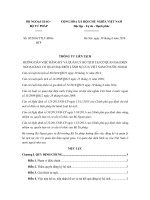
5.4.1 Split, knife cut (Fig. 1 and Fig. 2).
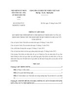
5.4.2 Machined (Fig. 3 and Fig. 4).
4
Supporting data have been filed at ASTM International Headquarters and may
be obtained by requesting Research Report RR:F03-1001.
Copyright © ASTM International, 100 Barr Harbor Drive, PO Box C700, West Conshohocken, PA 19428-2959. United States
1
F336 − 02 (2016)
TABLE 1 Nominal Gasket SizesA
NOTE 1—Refer to Fig. 1 through Fig. 6 for explanation of gasket
component details.
NOTE 2—Split design inserts not to be smaller than nominal pipe size.
NOTE 3—Inside diameter of folded and machined design envelopes will
adjoin the insert inside diameter assuring noninterference with flow
through pipe.
NOTE 4—Full face gaskets shall have envelope outside diameter same
as ring gasket outside diameter.
NOTE 5—Sizes 14 in. (356 mm) and larger may be made from machined
envelopes depending upon material shape availability.
Insert (2) (See Note 1)
Envelope (1) (See Note 1)
IV. Flat
III. Full
Ring
Face
V. (Each VI. Inside
Gasket
VII. Outside
Outside
Side)
Diameter
Outside
Diameter (C)
Diameter
Thickness
(A)
Diameter
(D)
(C)
Nominal
Pipe
Size, in.
II. Inside
Diameter
(B)
in.
in.
in.
in.
⁄
3⁄4
1
1 1⁄ 4
1 1⁄ 2
2
2 1⁄ 2
3
3 1⁄ 2
4
5
6
8
10
12
14
0.84
1.06
1.31
1.66
1.91
2.38
2.88
3.50
4.00
4.50
5.56
6.62
8.62
10.75
12.75
14.00
3.50
3.88
4.25
4.63
5.00
6.00
7.00
7.50
8.50
9.00
10.00
11.00
13.50
16.00
19.00
21.00
1.88
2.25
2.62
3.00
3.38
4.12
4.88
5.38
6.38
6.88
7.75
8.75
11.00
13.38
16.13
17.75
0.015
0.015
0.020
0.020
0.020
0.020
0.020
0.020
0.020
0.020
0.020
0.020
0.020
0.020
0.020
0.015
16
18
20
24
30
36
42
48
54
60
72
84
96
16.00
18.00
20.00
24.00
30.00
36.00
42.00
48.00
54.00
60.00
72.00
84.00
96.00
23.50
25.00
27.50
32.00
38.75
46.00
53.00
59.50
66.25
73.00
86.50
99.75
113.25
20.25
21.62
23.88
28.25
34.75
41.25
48.00
54.50
61.75
68.12
81.38
94.25
107.25
12
in.
0.50
0.75
1.00
1.25
1.50
2.00
2.50
3.00
3.50
4.00
5.00
6.00
8.00
10.00
12.00
not
applicable—
0.015 see Note 5
0.015
0.015
0.015
0.015
0.015
0.015
0.015
0.015
0.015
0.015
0.015
0.015
in.
1.88
2.25
2.62
3.00
3.38
4.12
4.88
5.38
6.38
6.88
7.75
8.75
11.00
13.38
16.12
17.00
FIG. 1 Split Design (Flat Ring)
19.00
21.00
23.00
27.00
33.00
39.00
45.00
51.00
57.00
63.00
75.00
87.00
99.00
A
Extracted from American National Standard Neometallic Gaskets for Pipe Sizes
(ANSI B16.21–2011), with the permission of the publisher. The American Society
of Mechanical Engineers, United Engineering Center, Three Park Avenue, New
York, NY 10016.
FIG. 2 Split Design (Full Face)
5.4.3 Tape Folded, made endless by joining tape ends with
a heat sealing procedure (Fig. 5 and Fig. 6).
6. Insert Classification5
6.2 Grades—Multiple layer constructions include the following:
6.2.1 Grade 1—Two layers, any combination of nonmetallic
homogenous materials.
6.2.2 Grade 2—Three layers, any combination of nonmetallic homogenous materials.
6.2.3 Grade 3, Three layers, the two outer layers nonmetallic homogenous materials, the inner layer (core) metallic.
6.1 Constructions—Two insert constructions are covered as
follows:
6.1.1 Construction 1—Single layer.
6.1.2 Construction 2—Multiple layer.
5
See Fig. 1 through Fig. 6.
2
F336 − 02 (2016)
FIG. 3 Machined Design (Flat Ring)
FIG. 5 Folded Design (Flat Ring)
FIG. 4 Machined Design (Full Face)
FIG. 6 Folded Design (Full Face)
6.3 Type—This classification covers insert material types as
follows:
6.3.1 Nonmetallic—Any recognized nonmetallic gasket material in accordance with Classification F104, taking into
consideration limitations with regard to temperature and pressure.
6.3.2 Metallic—Inner layer (core) metallic material in Construction 2, Grade 3.
6.3.2.1 Flat solid metal center.
6.3.2.2 Corrugated metal center.
6.3.2.3 Perforated metal center.
6.3.2.4 Braided metal center.
6.3.2.5 As specified.
6.4 Construction 2, multiple layer inserts may be preassembled by gluing, taping, or any other suitable method
before inserting in the envelope.
6.5 Elastomeric materials with high flow or creep properties
have a tendency to stretch and split the envelope and are not
recommended unless special provisions are made in the design.
3
F336 − 02 (2016)
6.6 Insert materials are not required to be corrosion-resistant
in most cases since they are separated from the corrosives by
the corrosion-resistant envelope.
forming has been completed, using the methods described in
Specifications D3308 for tape and D3294 for machined
articles, Type 1, Grade 1.
6.7 Extremely hard materials (such as solid metal or phenolic laminates) are not recommended for single layer construction inserts or the outer inserts in multiple layer constructions since excessive bolt torquing would be required to effect
a satisfactory seal.
7.2 Commercial dimensional tolerances apply unless otherwise agreed upon between the seller and the purchaser.
8. Keywords
8.1 corrosive service; enveloped; gaskets; nonmetallic;
polytetrafluoroethylene (PTFE)
6.8 For determining the suitability of inserts to seal
satisfactorily, Test Method F112 is recommended.
7. Inspection
7.1 Inspect electrically the corrosion-resistant materials
used as shields for enveloped gaskets after all machining and
ASTM International takes no position respecting the validity of any patent rights asserted in connection with any item mentioned
in this standard. Users of this standard are expressly advised that determination of the validity of any such patent rights, and the risk
of infringement of such rights, are entirely their own responsibility.
This standard is subject to revision at any time by the responsible technical committee and must be reviewed every five years and
if not revised, either reapproved or withdrawn. Your comments are invited either for revision of this standard or for additional standards
and should be addressed to ASTM International Headquarters. Your comments will receive careful consideration at a meeting of the
responsible technical committee, which you may attend. If you feel that your comments have not received a fair hearing you should
make your views known to the ASTM Committee on Standards, at the address shown below.
This standard is copyrighted by ASTM International, 100 Barr Harbor Drive, PO Box C700, West Conshohocken, PA 19428-2959,
United States. Individual reprints (single or multiple copies) of this standard may be obtained by contacting ASTM at the above
address or at 610-832-9585 (phone), 610-832-9555 (fax), or (e-mail); or through the ASTM website
(www.astm.org). Permission rights to photocopy the standard may also be secured from the Copyright Clearance Center, 222
Rosewood Drive, Danvers, MA 01923, Tel: (978) 646-2600; />
4