Astm f 593 17
Bạn đang xem bản rút gọn của tài liệu. Xem và tải ngay bản đầy đủ của tài liệu tại đây (133.29 KB, 9 trang )
This international standard was developed in accordance with internationally recognized principles on standardization established in the Decision on Principles for the
Development of International Standards, Guides and Recommendations issued by the World Trade Organization Technical Barriers to Trade (TBT) Committee.
Designation: F593 − 17
Standard Specification for
Stainless Steel Bolts, Hex Cap Screws, and Studs1
This standard is issued under the fixed designation F593; the number immediately following the designation indicates the year of original
adoption or, in the case of revision, the year of last revision. A number in parentheses indicates the year of last reapproval. A superscript
epsilon (´) indicates an editorial change since the last revision or reapproval.
This standard has been approved for use by agencies of the U.S. Department of Defense.
1.5 The values stated in inch-pound units are to be regarded
as standard. The values given in parentheses are mathematical
conversions to SI units that are provided for information only
and are not considered standard.
1.6 This standard does not purport to address all of the
safety concerns, if any, associated with its use. It is the
responsibility of the user of this standard to establish appropriate safety and health practices and determine the applicability of regulatory limitations prior to use.
1.7 This international standard was developed in accordance with internationally recognized principles on standardization established in the Decision on Principles for the
Development of International Standards, Guides and Recommendations issued by the World Trade Organization Technical
Barriers to Trade (TBT) Committee.
1. Scope*
1.1 This specification covers the requirements for stainless
steel bolts, hex cap screws, and studs 0.25 to 1.50 in., inclusive,
in nominal diameter in a number of alloys in common use and
intended for service applications requiring general corrosion
resistance.
1.2 Seven groups of stainless steel alloys are covered,
including fourteen austenitic, two ferritic, four martensitic, and
one precipitation hardening.
Group
1
2
3
4
5
6
7
AlloysA
304, 305, 384, 304 L,
18-9LW, 302HQ, 304J3D
316, 316 L
321, 347
430E
410F
431
630
ConditionB
(CW) cold workedC
(CW) cold workedC
(CW) cold workedC
(CW) cold workedC
(H) hardened and tempered
(H) hardened and tempered
(AH) age hardened
2. Referenced Documents
2.1 ASTM Standards:2
A262 Practices for Detecting Susceptibility to Intergranular
Attack in Austenitic Stainless Steels
A276 Specification for Stainless Steel Bars and Shapes
A342/A342M Test Methods for Permeability of Weakly
Magnetic Materials
A380 Practice for Cleaning, Descaling, and Passivation of
Stainless Steel Parts, Equipment, and Systems
A484/A484M Specification for General Requirements for
Stainless Steel Bars, Billets, and Forgings
A493 Specification for Stainless Steel Wire and Wire Rods
for Cold Heading and Cold Forging
A555/A555M Specification for General Requirements for
Stainless Steel Wire and Wire Rods
A564/A564M Specification for Hot-Rolled and ColdFinished Age-Hardening Stainless Steel Bars and Shapes
A582/A582M Specification for Free-Machining Stainless
Steel Bars
A751 Test Methods, Practices, and Terminology for Chemical Analysis of Steel Products
A
Unless otherwise specified on the inquiry and order, the choice of an alloy from
within a group shall be at the discretion of the fastener manufacturer (see 6.1).
B
See 4.2 for options.
C
Sizes 0.75 in. and larger may be hot worked and solution annealed, provided the
bolts comply with the cold worked (CW) mechanical property requirements.
D
When approved by the purchaser, Alloys 303, 303Se, or XM1 may be furnished.
E
When approved by the purchaser, Alloy 430F may be furnished.
F
When approved by the purchaser, Alloys 416 or 416Se may be furnished.
1.3 Supplementary requirements of an optional nature are
provided, applicable only when agreed upon between the
manufacturer and the purchaser at the time of the inquiry and
order.
1.4 Suitable nuts for use with bolts, hex cap screws, and
studs included in this specification are covered by Specification
F594. Unless otherwise specified, all nuts used on these
fasteners shall conform to the requirements of Specification
F594, shall be of the same alloy group, and shall have a
specified minimum proof stress equal to or greater than the
specified minimum full-size tensile strength of the externally
threaded fastener.
1
This specification is under the jurisdiction of ASTM Committee F16 on
Fasteners and is the direct responsibility of Subcommittee F16.04 on Nonferrous
Fasteners.
Current edition approved June 1, 2017. Published June 2017. Originally
approved in 1978. Last previous edition approved in 2013 as F593 – 13aɛ1. DOI:
10.1520/F0593-17.
2
For referenced ASTM standards, visit the ASTM website, www.astm.org, or
contact ASTM Customer Service at For Annual Book of ASTM
Standards volume information, refer to the standard’s Document Summary page on
the ASTM website.
*A Summary of Changes section appears at the end of this standard
Copyright © ASTM International, 100 Barr Harbor Drive, PO Box C700, West Conshohocken, PA 19428-2959. United States
1
F593 − 17
4.1.3 Threads—Unless otherwise specified, the threads shall
be rolled or cut at the option of the manufacturer.
A967 Specification for Chemical Passivation Treatments for
Stainless Steel Parts
D3951 Practice for Commercial Packaging
E29 Practice for Using Significant Digits in Test Data to
Determine Conformance with Specifications
F594 Specification for Stainless Steel Nuts
F606/F606M Test Methods for Determining the Mechanical
Properties of Externally and Internally Threaded
Fasteners, Washers, Direct Tension Indicators, and Rivets
F1470 Practice for Fastener Sampling for Specified Mechanical Properties and Performance Inspection
2.2 ASME Standards:3
B1.1 Unified Inch Screw Threads
B18.2.1 Square and Hex Bolts and Screws, Including Hex
Cap Screws
2.3 JIS Standard:4
JIS G4309 Stainless Steel Wires
4.2 Condition—The fasteners shall be furnished in the
following conditions, unless specified to be furnished in one of
the optional conditions:
Alloy Group
1, 2, 3
4
5
6
7
Condition Furnished Unless
Otherwise Specified
CW
CW
H
H
AH
Optional Conditions (must
be specified)
AF, A, SH
A
HT
HT
none
A— Machined from annealed or solution-annealed stock thus retaining the
properties of the original material; or hot-formed and solution annealed.
AF— Headed and rolled from annealed stock and then reannealed.
AH— Solution-annealed and age-hardened after forming.
CW— Headed and rolled from annealed stock thus acquiring a degree of cold
work. Sizes 0.75 in. and larger may be hot-worked and solutionannealed.
H— Hardened and tempered at 1050°F (565°C) minimum.
HT— Hardened and tempered at 525°F (274°C) minimum.
SH— Machined from strain-hardened stock or cold-worked to develop the
specific properties.
3. Ordering Information
3.1 Orders for bolts, hex cap screws, and studs under this
specification shall include the following:
3.1.1 Quantity (number of pieces of each item and size),
3.1.2 Name of item (bolt, hex cap screw, stud, etc.),
3.1.3 Size (nominal diameter, threads per inch, length; see
Section 9),
3.1.4 Alloy group number (see 6.1), and
3.1.5 Condition (see 4.2).
5. Heat Treatment
5.1 Alloy Groups 1, 2, and 3 (Austenitic Alloys 303, 303Se,
304, 304 L, 305, 316, 316 L, 321, 347, 384, XM1, 18-9LW,
302HQ, and 304J3):
5.1.1 Condition A—When Condition A is specified, the
austenitic alloys shall be heated to 1900 6 50°F (1038 6
28°C), at which time the chromium carbide will go into the
solution, be held for a sufficient time, and then be cooled at a
rate sufficient to prevent precipitation of the carbide and to
provide the specified properties.
5.1.2 Condition CW—When Condition CW is specified, the
austenitic alloys shall be annealed in accordance with 5.1.1,
generally by the raw material manufacturer and then cold
worked to develop the specified properties.
5.1.3 Condition AF—When Condition AF is specified, the
austenitic alloys shall be annealed in accordance with 5.1.1
after all cold working (including heading and threading) has
been completed.
3.2 Orders for bolts, hex cap screws, and studs under this
specification may include the following optional requirements:
3.2.1 Forming (see 4.1.2),
3.2.2 Rolled or cut threads (see 4.1.3),
3.2.3 Composition (see 6.2),
3.2.4 Corrosion Resistance (see 8.1),
3.2.5 Finish (see 10.3),
3.2.6 Rejection (see 16.1), and
3.2.7 Test report (see 17.2).
3.2.8 Supplementary requirements, if any, to be specified on
the order (see S1 through S8), and
3.2.9 ASTM specification and year of issue. When year of
issue is not specified, fasteners shall be furnished to the latest
issue.
5.2 Alloy Group 4 (Ferritic Alloys 430 and 430F):
5.2.1 Condition A—The ferritic alloys shall be heated to a
temperature of 1450 6 50°F (788 6 28°C), held for an
appropriate time, and then air cooled to provide the specified
properties.
5.2.2 Condition CW—When Condition CW is specified, the
ferritic alloys shall be annealed in accordance with 5.2.1,
generally by the raw material manufacturer and then cold
worked to develop the specified properties.
5.2.3 Condition AF—When Condition AF is specified, the
ferritic alloys shall be annealed in accordance with 5.2.1 after
all cold working (including heading and threading) has been
completed.
NOTE 1—Example 10 000 pieces, Hex Cap Screw, 0.250 in. −20 × 3.00
in., Alloy Group 1, Condition CW, Furnish Test Report, Supplementary
Requirement S3.
4. Manufacture
4.1 Manufacture:
4.1.1 Specifications A276, A493, A564/A564M, and A582/
A582M are noted for information only as suitable sources of
material for the manufacture of bolts, hex cap screws, and studs
to this specification.
4.1.2 Forming—Unless otherwise specified, the fasteners
shall be cold formed, hot formed, or machined from suitable
material at the option of the manufacturer.
5.3 Alloy Group 5 (Martensitic Alloys 410, 416, and 416Se):
5.3.1 Condition H—When Condition H is specified, the
Martensitic Alloys 410, 416, and 416Se shall be hardened and
tempered by heating to 1850 6 50°F (1010 6 28°C) sufficient
for austenitization, held for at least 1⁄2 h and rapid air- or
3
Available from Global Engineering Documents, 15 Inverness Way, East
Englewood, CO 80112-5704, .
4
Available from Japanese Industrial Standards Committee (JIS) 1-3-1
Kasumigaski, Chiyoda-ku, Tokyo 100-8901, Japan. http:www.jisc.go.jp
2
F593 − 17
oil-quenched, and then reheating to 1050°F (565°C) minimum
for at least 1 h and air cooled to provide the specified
properties.
5.3.2 Condition HT—When Condition HT is specified, the
Martensitic Alloys 410, 416, and 416Se shall be hardened and
tempered by heating to 1850 6 50°F (1010 6 28°C) sufficient
for austenitization, held for at least 1⁄2 h and rapid air- or
oil-quenched, and then reheating to 525°F (274°C) minimum
for at least 1 h and air cooled to provide the specified
properties.
Alloy Group
1
Alloys
304, 304 L, 305, 384, 18-9LW, 302HQ,
304J3A
316, 316 L
321, 347
430B
410C
431
630
2
3
4
5
6
7
A
When approved by the purchaser, Alloys 303, 303Se, or XM1 may be furnished.
When approved by the purchaser, Alloy 430F may be furnished.
C
When approved by the purchaser, Alloys 416 or 416Se may be furnished.
B
5.4 Alloy Group 6 (Martensitic Alloy 431):
5.4.1 Conditions H and HT—Martensitic Alloy 431 shall be
hardened and tempered in accordance with 5.3.1 and 5.3.2 as
applicable.
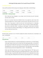
6. Chemical Composition
6.2 Chemical Composition Limits:
6.2.1 Ordering by Alloy Group—Unless otherwise specified
on the inquiry and order (see Supplementary Requirement S4),
the choice of an alloy from within a group shall be at the
discretion of the fastener manufacturer as required by his
method of fastener fabrication and material availability. The
specific alloy used by the fastener manufacturer shall be clearly
identified on any certification required by the order and shall
have a chemical composition conforming to the requirements
of Table 1 for the specific alloy.
6.2.2 Ordering by Specific Alloy—When ordered by a specific alloy number, the fasteners shall conform to the chemical
composition limits of Table 1 for the specific alloy.
6.1 Alloy Groups—It is the intent of this specification that
fasteners shall be ordered by alloy group numbers, which
include alloys considered to be chemically equivalent for
general purpose use. The alloy groupings are shown as follows.
The purchaser has the option of ordering a specific alloy, in
stead of an alloy group number, as permitted in 6.2.2.
6.3 Product Analysis:
6.3.1 When performed, product analysis to determine
chemical composition shall be performed on at least one fully
manufactured finished fastener representing each lot. The
chemical composition thus determined shall conform to the
requirements of Table 1 for the specified alloy or alloy group as
5.5 Alloy Group 7 (Precipitation Hardening Alloy 630):
5.5.1 Condition AH—Precipitation Hardening Alloy 630
shall be solution annealed and aged by heating to 1900 6 25°F
(1038 6 14°C) for at least 1⁄2 h and rapid air- or oil-quenched
to 80°F (27°C) maximum, then reheating to a temperature of
1150 6 15°F (621 6 8°C) for 4 h and air cooled to provide the
specified properties.
TABLE 1 Chemical Requirements
Alloy
UNS
Group Designation
Alloy
Composition, % maximum except as shown
Carbon
Manganese
Phosphorus
Sulfur
0.15 min
0.060
0.030
0.030
0.030
0.030
0.18 to 0.35
0.030
0.030
0.030
0.030
0.030
0.030
0.030
1
1
1
1
1
1
1
1
1
1
2
2
3
3
S30300
S30323
S30400
S30403
S30500
S38400
S20300
S30430
S30433
...
S31600
S31603
S32100
S34700
303
303 Se
304
304 L
305
384
XM1
18–9LW
302HQ
304J3B
316
316 L
321
347
0.15
0.15
0.08
0.03
0.12
0.08
0.08
0.10
0.03
0.08
0.08
0.03
0.08
0.08
2.00
2.00
2.00
2.00
2.00
2.00
5.0 to 6.5
2.00
2.00
2.00
2.00
2.00
2.00
2.00
0.20
0.20
0.045
0.045
0.045
0.045
0.040
0.045
0.045
0.045
0.045
0.045
0.045
0.045
4
4
S43000
S43020
430
430F
0.12
0.12
1.00
1.25
0.040
0.060
5
5
5
6
S41000
S41600
S41623
S43100
410
416
416Se
431
0.15
0.15
0.15
0.20
1.00
1.25
1.25
1.00
0.040
0.060
0.060
0.040
7
S17400
630
0.07
1.00
0.040
Silicon
Chromium
Nickel
Austenitic Alloys
1.00
17.0 to 19.0
8.0 to 10.0
1.00
17.0 to 19.0
8.0 to 10.0
1.00
18.0 to 20.0
8.0 to 10.5
1.00
18.0 to 20.0
8.0 to 12.0
1.00
17.0 to 19.0
10.5 to 13.0
1.00
15.0 to 17.0
17.0 to 19.0
1.00
16.0 to 18.0
5.0 to 6.5
1.00
17.0 to 19.0
8.0 to 10.0
1.00
17.0 to 19.0
8.0 to 10.0
1.00
17.0 to 19.0
8.0 to 10.5
1.00
16.0 to 18.0
10.0 to 14.0
1.00
16.0 to 18.0
10.0 to 14.0
1.00
17.0 to 19.0
9.0 to 12.0
1.00
17.0 to 19.0
9.0 to 13.0
Ferritic Alloys
0.030
1.00
16.0 to 18.0
...
0.15 min
1.00
16.0 to 18.0
Martensitic Alloys
0.030
1.00
11.5 to 13.5
0.15 min
1.00
12.0 to 14.0
...
0.060
1.00
12.0 to 14.0
0.030
1.00
15.0 to 17.0
1.25 to 2.50
Precipitation Hardening Alloy
0.030
1.00
15.0 to 17.5
3.0 to 5.0
A
At manufacturer’s option, determined only when intentionally added.
B
304J3 from JIS Standard G4309.
3
Copper
Molybdenum
Others
...
...
1.00
1.00
1.00
...
1.75 to 2.25
3.0 to 4.0
3.0 to 4.0
1.00 to 3.00
...
...
...
...
0.60 maxA
...
...
...
...
0.50 maxA
...
...
...
...
2.00 to 3.00
2.00 to 3.00
...
...
...
Se 0.15 min
...
...
...
...
...
...
...
...
...
...
Ti 5× C min
Cb+Ta 10 × C min
...
0.60 maxA
...
...
0.60 maxA
...
...
Se 0.15 min
...
3.0 to 5.0
...
Cb+Ta 0.15–0.45
F593 − 17
9.1.2 When specified, the dimensions of bolts shall be in
accordance with the requirements of ASME B18.2.1 (type as
specified), or such other dimensions shall be specified.
appropriate, subject to the Product Analysis Tolerance in
Specifications A484/A484M and A555/A555M.
6.3.2 In the event of discrepancy, a referee chemical analysis of samples from each lot shall be made in accordance with
14.1.
9.2 Studs—Dimensions of studs including double-end
clamping and double-end interference shall be as specified by
the purchaser.
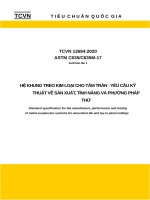
7. Mechanical Properties
9.3 Threads—Unless otherwise specified, the bolts, cap
screws, and studs shall have Class 2A threads in accordance
with ASME B1.1.
7.1 The finished fasteners shall meet the applicable mechanical property and test requirements of Table 2 and Table 3
as appropriate for the specified alloy group and condition and
shall be tested for conformance to the mechanical property
requirements as specified herein.
9.4 Points—Unless otherwise specified, the points shall be
flat and chamfered or rounded, at the option of the manufacturer.
7.2 Fasteners having a nominal thread diameter-length combination as follows:
Thread Diameter, in.
0.75 or less
Over 0.75
10. Workmanship and Finish
Thread Length, in.
2.25 D or longer
3 D or longer
10.1 Workmanship—The fasteners shall have a workmanlike finish, free of injurious burrs, seams, laps, irregular
surfaces, and other defects affecting serviceability.
and a breaking load of 120 000 lbf (535 kN) or less shall be
tested full size and shall meet the full-size tensile (minimum
and maximum) and yield strength requirements in Table 2
for the specified alloy.
7.3 Fasteners having a nominal thread diameter-length combination in accordance with 7.2 and a breaking load exceeding
120 000 lbf (535 kN) shall be tested full-size and shall meet the
full size tensile (minimum and maximum) and yield strength
properties in Table 2. When equipment of sufficient capacity
for such tests is not available, or if excessive length of the
fasteners makes full-size testing impractical, use of standard or
round specimens that meet the “machined specimen test tensile
properties” in Table 2 is permitted. In the event of discrepancy
or dispute between test results obtained from full-size finished
fasteners and standard or round specimens, the referee method
shall be tests performed on full-size finished fasteners.
10.2 Cleaning and Descaling—The fasteners shall be descaled or cleaned, or both, in accordance with Specification
A380.
10.3 Protective Finishes—Unless otherwise specified, the
fasteners shall be furnished without an additive chemical or
metallic finish.
11. Sampling
11.1 A lot, for the purposes of selecting test specimens, shall
consist of not more than 100 000 pieces offered for inspection
at one time having the following common characteristics:
11.1.1 One type of item (that is, bolts, hex cap screws, studs,
etc.),
11.1.2 Same alloy and condition,
11.1.3 One nominal diameter and thread series,
11.1.4 One nominal length,
11.1.5 Produced from one heat of material, and
11.1.6 Heat treated under the same conditions as to time and
temperature.
7.4 Fasteners that are too short (lengths less than that
specified in 7.2 (see Test Methods F606/F606M and Table 4);
have insufficient threads for tension; or have drilled or undersized heads, drilled or reduced bodies, and so forth, that are
weaker than the thread section, shall not be subject to tension
tests but shall conform to the hardness (minimum and maximum) requirements of Table 2.
12. Number of Tests and Retests
12.1 Number of Tests:
12.1.1 Mechanical Tests—The mechanical requirements of
this specification shall be met in continuous mass production
for stock. The manufacturer shall make sample inspections as
specified below to ensure that the product conforms to the
specified requirements. When tests of individual shipments are
required, Supplementary Requirement S1 must be specified in
the inquiry and order.
8. Corrosion Resistance
8.1 Carbide Precipitation:
8.1.1 Rod, bar, and wire in the austenitic Alloy Groups 1, 2,
and 3, except the free-machining grades, 303 and 303Se, used
to make fasteners in accordance with this specification shall be
capable of passing the test for susceptibility to intergranular
corrosion as specified in Practice E of Practices A262.
8.1.2 As stated in Practice A262, samples may be subjected
to the faster and more severe screening test in accordance with
Practice A. Failing Practice A, specimens shall be tested in
accordance with Practice E and be considered satisfactory if
passing Practice E.
Number of Pieces in Lot
2 to 50
51 to 500
501 to 35 000
35 001 to 100 000
9. Dimensions
Number of
Tests
2
3
5
8
Acceptance Criteria
Acceptance
Number
0
0
0
0
Rejection
Number
1
1
1
1
12.1.2 Corrosion Resistance Tests:
12.1.2.1 Unless otherwise specified, inspection for corrosion resistance shall be in accordance with the manufacturer’s
standard quality control practices. No specific method of
inspection is required, but the fasteners shall be produced from
9.1 Bolts and Hex Cap Screws:
9.1.1 Unless otherwise specified, the dimensions shall be in
accordance with the requirements of ASME B18.2.1 for hex
cap screws (finished hex bolts).
4
F593 − 17
TABLE 2 Mechanical Property RequirementsA
Stainless Alloy Group
1
(303, 304,
304 L, 305,
384,
XM1,
18-9LW,
302HQ,
304J3,
303Se)
2
(316,
43
G
316L)
3
(321, 347)
4
(430, 430F)
5
(410, 416,
416Se)
6
(431)
7
(630)
G
3
3
Alloy Mechanical
Property Marking
Nominal
Diameter,
in.
AF
F593A
Tensile
Strength
ksiC
Austenitic Alloys
1⁄4 to 11⁄2, incl
65 to 85
A
F593B
14
CW1
F593C
CW2
F593D
SH1
F593A
SH2
F593B
SH3
ConditionB
⁄ to 11⁄2, incl
75 to 100
Full-Size Tests
Yield
Strength,
ksiD,C
Rockwell
Hardness
Machined Specimen Tests
Yield
ElonTensile
Strength,
gation
Strength
ksiD,C
in 4 D, %
ksiC
20
B85 max
60
20
40
30
B65 to 95
70
30
30
⁄ to ⁄ , incl
100 to 150
65
B95 to C32
95
60
20
⁄ to 11⁄2, incl
85 to 140
45
B80 to C32
80
40
25
⁄ to 5⁄8, incl
120 to 160
95
C24 to C36
115
90
12
⁄ to 1, incl
110 to 150
75
C20 to C32
105
70
15
F593C
11⁄8 to 11⁄4, incl
100 to 140
60
B95 to C30
95
55
20
SH4
F593D
13⁄8 to 11⁄2, incl
95 to 130
45
B90 to C28
90
40
28
AF
F593E
14
⁄ to 11⁄2, incl
65 to 85
20
B85 max
60
20
40
A
F593F
14
⁄ to 11⁄2, incl
75 to 100
30
B65 to 95
70
30
30
CW1
F593G
⁄ to 5⁄8, incl
100 to 150
65
B95 to C32
95
60
20
CW2
F593H
⁄ to 11⁄2, incl
85 to 140
45
B80 to C32
80
40
25
SH1
F593E
⁄ to 5⁄8, incl
120 to 160
95
C24 to C36
115
90
12
SH2
F593F
⁄ to 1, incl
110 to 150
75
C20 to C32
105
70
15
SH3
F593G
1 ⁄ to 1 ⁄ , incl
100 to 140
60
B95 to C30
95
55
20
SH4
F593H
13⁄8 to 11⁄2, incl
95 to 130
45
B90 to C28
90
40
28
AF
F593J
14
⁄ to 11⁄2, incl
65 to 85
20
B85 max
60
20
40
A
F593K
14
⁄ to 11⁄2, incl
75 to 100
30
B65 to 95
70
30
30
CW1
F593L
⁄ to 5⁄8, incl
100 to 150
65
B95 to C32
95
60
20
CW2
F593M
SH1
F593J
SH2
F593K
14
58
34
14
34
14
34
14
34
18
14
14
⁄ to 11⁄2, incl
85 to 140
45
B80 to C32
80
40
25
58
⁄ to ⁄ , incl
120 to 160
95
C24 to C36
115
90
12
⁄ to 1, incl
110 to 150
75
C20 to C32
105
70
15
34
14
34
100 to 140
60
B95 to C30
95
55
20
45
B90 to C28
90
40
28
F593X
F593N
95 to 130
Ferritic Alloys
1⁄4 to 11⁄2, incl
55 to 75
1⁄4 to 11⁄2, incl
55 to 75
30
30
B85 max
B85 max
50
50
25
25
...
...
CW1
CW2
F593V
F593W
34
40
30
B75 to 98
B65 to 95
55
50
35
25
...
...
H
HT
F593P
F593R
⁄ to 5⁄8, incl
60 to 105
⁄ to 11⁄2, incl
55 to 100
Martensitic Alloys
1⁄4 to 11⁄2, incl
110 to 140
1⁄4 to 11⁄2, incl
160 to 190
90
120
C20 to 30
C34 to 45
110
160
90
120
18
12
H
HT
F593S
F593T
C25 to 32
C40 to 48
125
180
100
140
15
10
AH
F593U
⁄ to 11⁄2, incl
125 to 150
100
⁄ to 11⁄2, incl
180 to 220
140
Precipitation Hardening Alloys
1⁄4 to 11⁄2, incl
135 to 170
105
C28 to 38
135
105
16
SH3
F593L
11⁄8 to 11⁄4, incl
SH4
F593M
13⁄8 to 11⁄2, incl
AF
A
14
14
14
A
Minimum values except where shown as maximum or as a range.
Legend of conditions:
A—Machined from annealed or solution-annealed stock thus retaining the properties of the original material, or hot-formed and solution-annealed.
AF—Headed and rolled from annealed stock and then reannealed.
AH—Solution annealed and age-hardened after forming.
CW—Headed and rolled from annealed stock thus acquiring a degree of cold work; sizes 0.75 in. and larger may be hot worked and solution-annealed.
H—Hardened and tempered at 1050°F (565°C) minimum.
HT—Hardened and tempered at 525°F (274°C) minimum.
SH—Machined from strain hardened stock or cold-worked to develop the specified properties.
C
The yield and tensile strength values for full-size products shall be computed by dividing the yield and maximum tensile load values by the stress area for the product
size and thread series determined in accordance with Test Methods F606/F606M (see Table 4).
D
Yield strength is the stress at which an offset of 0.2 % gage length occurs.
B
5
F593 − 17
TABLE 3 Mechanical Test Requirements for Bolts and StudsA
Nominal Length
Item
Diameters 3⁄4 in.
and Less
less than 21⁄4 D
Square and hex
bolts and hex
cap screws
Studs and other
bolts
Full-Size Tests
Tensile
Diameters Over Load, lbf
3⁄4 in.
less than 3D
21⁄4 D and longer
3D and longer
less than 21⁄4 D
less than 3D
21⁄4 D and longer
3D and longer
SpecialsC
all
Wedge
Tensile
Strength
Axial Tensile
Strength
Machined Specimen Tests
Yield
Strength
Rockwell
Hardness
Tensile
Strength
Yield
Strength
Elongation
Option A
B
B
Option C
B
B
B
mandatory
B
mandatory
B
B
B
B
Option A
B
Option A
B
Option B
Option B
Option B
all
120 000
max
over
120 000
B
Option A
B
Option C
B
B
B
B
mandatory
mandatory
B
B
B
B
B
Option A
Option A
B
Option B
Option B
Option B
all
B
B
B
mandatory
B
B
B
all
120 000
max
over
120 000
all
A
Where options are given, all the tests under an option shall be performed. Option A, Option B, and Option C indicates manufacturer may perform all Option A (full-size),
all Option B (machined specimen), or all Option C tests whichever is preferred. Option A tests should be made whenever feasible.
B
Tests that are not mandatory.
C
Special fasteners are those fasteners with special configurations including drilled heads, reduced body, etc., that are weaker than the threaded section. Special fasteners
having full-size heads shall be tested as specified for studs and other bolts.
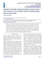
TABLE 4 Tensile Stress Areas and Threads per Inch
Nominal Size, in. (D)
Fine Threads-UNF
Thread Series–8 UN
Stress AreaA , in.2
Threads/in.
Stress AreaA , in.2
Threads/in.
Stress AreaA ,
in.2
⁄ (0.250)
⁄ (0.3125)
3⁄18 (0.375)
7⁄16 (0.4375)
1⁄2 (0.500)
20
18
16
14
13
0.0318
0.0524
0.0775
0.1063
0.1419
28
24
24
20
20
0.0364
0.0580
0.0878
0.1187
0.1599
...
...
...
...
...
...
...
...
...
...
⁄ (0.5625)
⁄ (0.625)
3⁄4 (0.750)
7⁄8 (0.875)
1.000
12
11
10
9
8
0.1820
0.2260
0.3340
0.4620
0.6060
18
18
16
14
12
0.2030
0.2560
0.3730
0.5090
0.6630
...
...
...
...
...
...
...
...
...
...
7
7
6
6
0.7630
0.9690
1.1550
1.4050
12
12
12
12
0.8560
1.0730
1.3150
1.5810
8
8
8
8
0.790
1.000
1.233
1.492
14
5 16
9 16
58
1 1 ⁄8
1 1 ⁄4
1 3 ⁄8
1 1 ⁄2
A
Coarse Threads–UNC
Threads/in.
(1.125)
(1.250)
(1.375)
(1.500)
Tensile stress areas are computed using the following formula:
F
A s 5 0.7854 D 2
0.9743
n
G
2
where:
As
= tensile stress area, in.2,
D
= nominal size (basic major diameter), in., and
n
= number of threads per inch.
12.2 Retests:
12.2.1 When tested in accordance with the required sampling plan, a lot shall be subject to rejection if any of the test
specimens fail to meet the applicable test requirements.
12.2.2 If the failure of a test specimen is due to improper
preparation of the specimen or to incorrect testing technique,
the specimen shall be discarded and another specimen substituted.
suitable raw material and manufactured by properly controlled
practices to maintain resistance to corrosion. When corrosion
tests are required, Supplementary Requirement S7 must be
specified in the inquiry and order, except as noted in 12.1.2.2.
12.1.2.2 Products that have been hot worked shall be
solution annealed and tested to determine freedom from
precipitated carbides. Not less than one corrosion test shall be
made from each lot. Corrosion tests shall be performed in
accordance with Practice A262, Practices A or E as applicable.
6
F593 − 17
13. Significance of Numerical Limits
16. Rejection and Rehearing
13.1 For the purposes of determining compliance with the
specified limits for properties listed in this specification, an
observed value or calculated value shall be rounded in accordance with Practice E29.
16.1 Unless otherwise specified, any rejection based on tests
specified herein and made by the purchaser shall be reported to
the manufacturer within 30 working days from the receipt of
the product by the purchaser.
14. Test Specimens
17. Certification and Test Reports
14.1 Chemical Tests—When required, samples for chemical
analysis shall be taken by drilling, sawing, milling, turning,
clipping, or other such methods capable of producing representative samples.
17.1 Certificate of Compliance—Unless otherwise specified
in the purchase order, the manufacturer shall furnish certification that the product was manufactured and tested in accordance with this specification and the customer’s order and
conforms to all specified requirements.
14.2 Mechanical Tests:
14.2.1 Specimens shall be full size or machined in accordance with 7.2 through 7.4. Machined specimens, when
required, shall be machined from the fastener in accordance
with Test Methods F606/F606M.
14.2.2 The hardness shall be determined on the finished
fastener in accordance with Test Methods F606/F606M.
17.2 Test Reports—When specified on the order, the manufacturer shall furnish a test report showing the chemical
analysis of the fasteners and the results of the last completed
set of mechanical tests for each lot of fasteners in the shipment.
17.3 All certification shall indicate the purchase order number and the applicable requirements of Section 3.
14.3 Corrosion Resistance—Test specimens shall be prepared in accordance with Practices A262.
18. Product Marking
15. Test Methods
18.1 Individual Products—All products except studs 3⁄8 in.
in diameter and smaller shall be marked with a symbol
identifying the manufacturer. In addition, they shall be marked
with the alloy/mechanical property marking in accordance with
Table 2. The manufacturer may at his option add the specific
stainless alloy designation from Table 1. However, marking of
the stainless alloy designation does not signify compliance
with this specification. The marking shall be raised or depressed at the option of the manufacturer.
15.1 Chemical Analysis—The chemical composition shall
be determined in accordance with Test Methods A751.
15.1.1 The fastener manufacturer may accept the chemical
analysis of each heat of raw material purchased and reported on
the raw material certification furnished by the raw material
producer. The fastener manufacturer is not required to do any
further chemical analysis testing provided that precise heat lot
traceability has been maintained throughout the manufacturing
process on each lot of fasteners produced and delivered
19. Packaging and Package Marking
15.2 Mechanical Tests:
15.2.1 When full-size tests are to be performed, the yield
strength and wedge tensile strength or axial tensile strength, as
required by Section 7, shall be determined on each sample in
accordance with the appropriate methods of Test Methods
F606/F606M.
15.2.2 Full-size bolts and hex cap screws subject to tension
tests shall be tested using a wedge under the head. The wedge
shall be 10° for bolts 0.750-in. nominal diameter and less and
6° for bolts over 0.750-in. diameter.
15.2.3 When machined specimen tests are necessary (see
Section 7), the yield strength, tensile strength, and elongation
shall be determined on each sample in accordance with Test
Methods F606/F606M.
15.2.4 The hardness shall be determined in accordance with
Test Methods F606/F606M. A minimum of two readings shall
be made on each sample, each of which shall conform to the
specified requirements.
19.1 Packaging:
19.1.1 Unless otherwise specified, packaging shall be in
accordance with Practice D3951.
19.1.2 When special packaging requirements are required
by the purchaser, they shall be defined at the time of inquiry
and order.
19.2 Package Marking—Each shipping unit shall include or
be plainly marked with the following:
19.2.1 ASTM specification,
19.2.2 Alloy number,
19.2.3 Alloy/mechanical property marking,
19.2.4 Size,
19.2.5 Name and brand or trademark of manufacturer,
19.2.6 Number of pieces,
19.2.7 Country of origin,
19.2.8 Date of manufacture,
19.2.9 Purchase order number, and
19.2.10 Lot number, if applicable.
15.3 Corrosion Resistance—When specified on the purchase order or inquiry, corrosion tests to determine freedom
from precipitated carbides shall be performed in accordance
with Practice A262, Practice A or E as applicable.
20. Keywords
20.1 bolts; general use; hex cap screws; stainless; studs
7
F593 − 17
SUPPLEMENTARY REQUIREMENTS
One or more of the following supplementary requirements shall apply only when specified by the
purchaser in the inquiry and order (see Section 3). Supplementary requirements shall in no way negate
any requirement of the specification itself.
S4. Alloy Control
S4.1 When Supplementary Requirement S4 is specified on
the inquiry and order, the manufacturer shall supply that alloy
specified by the customer on his order with no group substitutions permitted without the written permission of the purchaser.
S1. Shipment Lot Testing
S1.1 When Supplementary Requirement S1 is specified on
the order, the manufacturer shall make sample tests on the
individual lots for shipment to ensure that the product conforms to the specified requirements.
S1.2 The manufacturer shall make an analysis of a randomly selected finished fastener from each lot of product to be
shipped. Heat or lot control shall be maintained. The analysis
of the starting material from which the fasteners have been
manufactured may be reported in place of the product analysis.
S1.3 The manufacturer shall perform mechanical property
tests in accordance with this specification and Guide F1470 on
the individual lots for shipment.
S1.4 The manufacturer shall furnish a test report for each lot
in the shipment showing the actual results of the chemical
analysis and mechanical property tests performed in accordance with Supplementary Requirement S1.
S5. Heat Control
S5.1 When Supplementary Requirement S5 is specified on
the inquiry or order, the manufacturer shall control the product
by heat analysis and identify the finished product in each
shipment by the actual heat number.
S5.2 When Supplementary Requirement S5 is specified on
the inquiry and order, Supplementary Requirements S1 and S4
shall be considered automatically invoked with the addition
that the heat analysis shall be reported to the purchaser on the
test reports.
S6. Permeability
S6.1 When Supplementary Requirement S6 is specified on
the inquiry and order, the permeability of bolts, hex cap screws,
and studs of Alloy Groups 1, 2, and 3 in Conditions A or AF
shall not exceed 1.5 at 100 oersteds when determined in
accordance with Test Methods A342/A342M.
S2. Additional Tests
S2.1 When additional tests of mechanical properties are
desired by the purchaser, the test(s) shall be made as agreed
upon between the manufacturer and the purchaser at the time of
the inquiry or order.
S7. Corrosion Resistance Tests
S7.1 When Supplementary Requirement S7 is specified on
the inquiry and order, corrosion test(s) shall be performed as
agreed upon between the manufacturer and the purchaser at the
time of the inquiry or order.
S3. Source Inspection
S3.1 When Supplementary Requirement S3 is specified on
the inquiry and order, the product shall be subject to inspection
by the purchaser at the place of manufacture prior to shipment.
The manufacturer shall afford the inspector all reasonable
facilities to satisfy that the product is being furnished in
accordance with this specification. All inspections and tests
shall be so conducted so as not to interfere unnecessarily with
the operations of the manufacturer.
S8. Passivation
S8.1 When Supplementary Requirement S8 is specified on
the inquiry or order, the finished product shall be passivated in
accordance with Practice A380 or Specification A967 at the
option of the manufacturer.
SUMMARY OF CHANGES
Committee F16 has identified the location of selected changes to this standard since the last issue
(F593 – 13aɛ1) that may impact the use of this standard.
(1) Added 304J3 to Apply Group in Table 1 and Table 2.
8
F593 − 17
ASTM International takes no position respecting the validity of any patent rights asserted in connection with any item mentioned
in this standard. Users of this standard are expressly advised that determination of the validity of any such patent rights, and the risk
of infringement of such rights, are entirely their own responsibility.
This standard is subject to revision at any time by the responsible technical committee and must be reviewed every five years and
if not revised, either reapproved or withdrawn. Your comments are invited either for revision of this standard or for additional standards
and should be addressed to ASTM International Headquarters. Your comments will receive careful consideration at a meeting of the
responsible technical committee, which you may attend. If you feel that your comments have not received a fair hearing you should
make your views known to the ASTM Committee on Standards, at the address shown below.
This standard is copyrighted by ASTM International, 100 Barr Harbor Drive, PO Box C700, West Conshohocken, PA 19428-2959,
United States. Individual reprints (single or multiple copies) of this standard may be obtained by contacting ASTM at the above
address or at 610-832-9585 (phone), 610-832-9555 (fax), or (e-mail); or through the ASTM website
(www.astm.org). Permission rights to photocopy the standard may also be secured from the Copyright Clearance Center, 222
Rosewood Drive, Danvers, MA 01923, Tel: (978) 646-2600; />
9