Astm f 480 14
Bạn đang xem bản rút gọn của tài liệu. Xem và tải ngay bản đầy đủ của tài liệu tại đây (437.3 KB, 26 trang )
Designation: F480 − 14
Standard Specification for
Thermoplastic Well Casing Pipe and Couplings Made in
Standard Dimension Ratios (SDR), SCH 40 and SCH 801
This standard is issued under the fixed designation F480; the number immediately following the designation indicates the year of original
adoption or, in the case of revision, the year of last revision. A number in parentheses indicates the year of last reapproval. A superscript
epsilon (´) indicates an editorial change since the last revision or reapproval.
This standard has been approved for use by agencies of the U.S. Department of Defense.
2. Referenced Documents
1. Scope*
2.1 ASTM Standards:2
D618 Practice for Conditioning Plastics for Testing
D638 Test Method for Tensile Properties of Plastics
D653 Terminology Relating to Soil, Rock, and Contained
Fluids
D1527 Specification for Acrylonitrile-Butadiene-Styrene
(ABS) Plastic Pipe, Schedules 40 and 80 (Withdrawn
2013)3
D1600 Terminology for Abbreviated Terms Relating to Plastics
D1784 Specification for Rigid Poly(Vinyl Chloride) (PVC)
Compounds and Chlorinated Poly(Vinyl Chloride)
(CPVC) Compounds
D1785 Specification for Poly(Vinyl Chloride) (PVC) Plastic
Pipe, Schedules 40, 80, and 120
D1892 Specification for Styrene-Butadiene Molding and
Extrusion Materials (Withdrawn 1987)3
D1898 Practice for Sampling of Plastics (Withdrawn 1998)3
D2122 Test Method for Determining Dimensions of Thermoplastic Pipe and Fittings
D2235 Specification for Solvent Cement for AcrylonitrileButadiene-Styrene (ABS) Plastic Pipe and Fittings
D2241 Specification for Poly(Vinyl Chloride) (PVC)
Pressure-Rated Pipe (SDR Series)
D2282 Specification for Acrylonitrile-Butadiene-Styrene
(ABS) Plastic Pipe (Withdrawn 2006)3
D2412 Test Method for Determination of External Loading
Characteristics of Plastic Pipe by Parallel-Plate Loading
D2444 Test Method for Determination of the Impact Resistance of Thermoplastic Pipe and Fittings by Means of a
Tup (Falling Weight)
D2564 Specification for Solvent Cements for Poly(Vinyl
Chloride) (PVC) Plastic Piping Systems
1.1 This specification covers water well casing pipe and
couplings made from thermoplastic materials in standard
dimension ratios (SDR), SCH 40 and SCH 80.
1.2 Specifications are provided for the application of these
materials to water well and ground water monitoring applications. Flush threaded joint systems are included for screen and
casing used primarily in the construction of ground water
monitoring wells (see Practice D5092).
1.3 The values stated in inch-pound units are to be regarded
as standard. The values given in parentheses are mathematical
conversions to SI units that are provided for information only
and are not considered standard. (See IEEE/ASTM SI 10.)
NOTE 1—Certain field conditions may require alternative materials to
ensure safe long-term use. The user should consult federal, state, and local
codes governing the use of thermoplastic materials for well casing or
monitor pipe.
NOTE 2—This standard specifies dimensional, performance and test
requirements for plumbing and fluid handling applications, but does not
address venting of combustion gases.
1.4 Although the pipe sizes and SDR values listed in this
specification are generally available, numerous other plastic
pipes in Schedule 40 and 80 wall, other SDR values and
various outside diameters have been used for well casing. Such
products are often selected because they fulfill certain needs
and Annex A1 includes a list of these Plastic Pipe Well Casing
Specials.
1.5 The following safety hazards caveat pertains only to the
test method portion, Section 6, of this specification: This
standard does not purport to address all of the safety concerns,
if any, associated with its use. It is the responsibility of the user
of this standard to establish appropriate safety and health
practices and determine the applicability of regulatory limitations prior to use.
2
For referenced ASTM standards, visit the ASTM website, www.astm.org, or
contact ASTM Customer Service at For Annual Book of ASTM
Standards volume information, refer to the standard’s Document Summary page on
the ASTM website.
3
The last approved version of this historical standard is referenced on
www.astm.org.
1
This specification is under the jurisdiction of ASTM Committee F17 on Plastic
Piping Systems and is the direct responsibility of Subcommittee F17.61 on Water.
Current edition approved March 1, 2014. Published March 2014. Originally
approved in 1976. Last previous edition approved in 2012 as F480 – 12. DOI:
10.1520/F0480-14.
*A Summary of Changes section appears at the end of this standard
Copyright © ASTM International, 100 Barr Harbor Drive, PO Box C700, West Conshohocken, PA 19428-2959. United States
1
F480 − 14
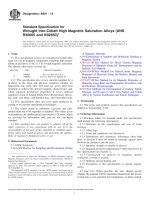
with a cell classification of 44322 or 33333, (2) Specification
D1784 for PVC with a cell classification of 12454 or 14333, or
(3) Specification D1892 for SR with a cell classification of
4434A. The material so described shall be approved for potable
water.
D2855 Practice for Making Solvent-Cemented Joints with
Poly(Vinyl Chloride) (PVC) Pipe and Fittings
D3122 Specification for Solvent Cements for StyreneRubber (SR) Plastic Pipe and Fittings
D3965 Classification System and Basis for Specifications for
Rigid Acrylonitrile-Butadiene-Styrene (ABS) Materials
for Pipe and Fittings
D5092 Practice for Design and Installation of Groundwater
Monitoring Wells
F402 Practice for Safe Handling of Solvent Cements,
Primers, and Cleaners Used for Joining Thermoplastic
Pipe and Fittings
F412 Terminology Relating to Plastic Piping Systems
IEEE/ASTM SI 10 American National Standard for Use of
the International System of Units (SI): The Modern Metric
System
2.2 ANSI Standards:4
B1.5 ACME Screw Threads
B1.8 Stub ACME Screw Threads
B1.9 Buttress Inch Screw Threads
2.3 Federal Standard:5
FED-STD-123 Marking for Shipment (Civil Agencies)
2.4 Military Standard:5
MIL-STD-129 Marking for Shipment and Storage
2.5 Other Standards:
Screw-Threads Standards for Federal Services 1957, Handbook H28, Part III6
NSF 14 Plastic Piping System Components and Related
Materials
NSF 61 Drinking Water System Components7
NOTE 3—Caution should be exercised to control heat of hydration
during grouting as thermoplastic materials are heat sensitive. Accelerators
tend to increase the heat of hydration and are not recommended.
5.2 Acrylonitrile-butadiene-styrene (ABS) well casing pipe
and couplings plastic shall be virgin plastic produced by the
original compounder (see Specification D1527). The minimum
butadiene content is 6 %; the minimum acrylonitrile content is
15 %; the minimum styrene or substituted styrene content, or
both, is 15 %; and the maximum content of other monomers is
5 % and lubricants, stabilizers, and colorants.
5.3 Poly(vinyl chloride) (PVC) well casing pipe and couplings plastic shall be made of virgin plastic produced by the
original compounder. It shall contain poly(vinyl chloride)
homopolymer, and such additives—stabilizers, lubricants, processing aids, impact improvers, and colorants—as needed to
provide the required processing and toughness characteristics
(see Test Method D638).
5.4 The SR plastics compound shall contain at least 50 %
styrene plastics, combined with rubbers to a minimum rubber
content of 5 %, and compounding materials such as antioxidants and lubricants, and may contain up to 15 % acrylonitrile
combined in the styrene plastics or rubbers, or both. The
rubbers shall be of the poly-butadiene or butadiene-styrene
type, or both, with a maximum styrene content of 25 % or
nitrile type, or both. The combined styrene plastics and rubber
content shall be not less than 90 %.
3. Terminology
3.1 Definitions are in accordance with Terminology F412
and abbreviations are in accordance with Terminology D1600,
unless otherwise specified. The abbreviation for acrylonitrilebutadiene-styrene plastic is ABS. The abbreviation for poly(vinyl chloride) is PVC. The abbreviation for styrene-rubber is
SR.
5.5 Rework Material—Clean rework material generated
from the manufacturer’s own well casing pipe and couplings
production may be used by the same manufacturer, provided
the well casing pipe and couplings produced meet all the
requirements of this specification.
5.6 Solvent Cement:
5.6.1 Specification—The solvent cement shall meet the
requirements of Specification D2235 for ABS, Specification
D2564 for PVC, or Specification D3122 for SR (see Supplementary Requirements S3).
3.2 Ground water investigation terms are in accordance with
Terminology D653.
4. Classification
4.1 Well casing is produced in either plain end, belled end,
or threaded, and is used for water wells, ground water
monitoring, leak detection, recovery systems, dewatering
systems, and waste disposal.
6. Requirements
6.1 Workmanship—The pipe shall be homogeneous
throughout and essentially uniform in color, opacity, density,
and other properties. The inside and outside surfaces shall be
semi-matte or glossy in appearance (depending on the type of
plastic) and free of chalking, sticky, or tacky material. The
surfaces shall be free of excessive bloom, that is, slight bloom
is acceptable. The pipe walls shall be free of cracks, holes,
blisters, voids, foreign inclusion, or other defects that are
visible to the naked eye and that may affect the wall integrity.
Machined slots or holes deliberately placed in pipe are acceptable. Bloom or chalking may develop in pipe exposed to direct
rays of the sun (ultraviolet radiant energy) for extended
periods, and consequently these requirements do not apply to
pipe after extended exposure to direct rays of the sun.
5. Materials and Manufacture
5.1 Specification—The material described shall meet or
exceed the requirements of (1) Specification D3965 for ABS
4
Available from American National Standards Institute (ANSI), 25 W. 43rd St.,
4th Floor, New York, NY 10036, .
5
DLA Document Services Building 4/D 700 Robbins Avenue Philadelphia, PA
19111-5094 />6
U.S. Government Bookstore 710 North Capitol Street N.W. Washington, DC
/>7
Available from NSF International, P.O. Box 130140, 789 N. Dixboro Rd., Ann
Arbor, MI 48113-0140, .
2
F480 − 14
6.3.4 Laying Length Dimensions—The laying length dimensions of well casing pipe couplings shall conform to the
requirements given in Table 3, Table 4, and Table 5 when
measured in accordance with Test Method D2122.
6.3.5 Socket Concentricity or Alignment—The maximum
misalignment of axis of couplings with the pipe measured in
the plane of the coupling face shall not exceed 3⁄4 in./20 ft (3
mm/1 m) of projected axis when measured in accordance with
7.4.
6.1.1 Ground Water Investigations—Pipe manufactured into
products used in ground water investigations should have
surfaces that are visually free of oils, grease, dust, and marks
imparted as a result of the manufacturing process.
6.2 Well Casing Pipe:
6.2.1 Dimensions—The outside diameter and wall thickness
of the well casing pipe shall meet the requirements given in
Table 1 or Table 2 when measured in accordance with Test
Method D2122. (See Specification D2282.)
6.2.2 Wall Thickness Eccentricity—The wall thickness eccentricity of the pipe shall be within 12 %.
6.2.3 Length—The well casing pipe shall be in either 10- or
20-ft (3.05- or 6.10-m) lengths, unless otherwise specified. The
allowable tolerance on length shall be +1⁄2, −0 in. (+13, −0 mm)
when measured in accordance with Test Method D2122.
6.2.4 Flush Joint Threaded Length—If specified by the
manufacturer or purchaser, the assembled length of flush
threaded casing or screen shall be a nominal length such as 5,
10, or 20 ft. Any given laying length the purchaser specifies
will constitute an assembled length. The allowable tolerance
shall be +1⁄2, −1⁄8 in. (+13, −3 mm) on the components of the
assembled laying length. The overall length of all flush
threaded screen and casing shall be the nominal or specified
laying length plus the length of the exposed male thread (pin).
6.4 Pipe Stiffness and Flattening:
6.4.1 Well Casing Pipe—The well casing pipe shall have a
pipe stiffness at 5 % deflection equal to that shown in Table 6
and Table 7 and shall deflect 60 % of the original diameter
(flattening) without cracking, rupture, or other visible evidence
of failure when tested in accordance with Test Method D2412.
Three specimens shall be tested and all shall pass.
NOTE 5—This test is intended for use as a quality control test, not as a
simulated service test.
6.4.2 Couplings and Bells shall meet all the designated
dimensional requirements of Table 3, Table 4, or Table 5.
Molded couplings shall have a pipe stiffness at 5 % deflection
equal to that shown in Table 6 and Table 7 and shall deflect
15 % without cracking, rupture, or other visible evidence of
failure when tested in accordance with Test Method D2412.
Three specimens shall be tested and all shall pass.
NOTE 4—The purchaser should specify whether the length is to be the
laying length or the overall length. The term “laying length” refers to the
overall length less the length required to complete the assembly.
6.5 Impact Resistance Classification—The impact resistance classification (IC) value for well casing pipe shall be
selected from Table 8 by the manufacturer based on the
measured average impact values determined in accordance
with 7.5.
6.3 Well Casing Pipe Couplings:
6.3.1 Socket Dimensions—The socket dimensions of couplings shall conform to the requirements given in Table 3 and
Table 4 when measured in accordance with Test Method
D2122.
6.3.2 Bell Socket Dimensions—The socket dimensions of
well casing pipe bell couplings shall be as shown in Table 5
when measured in accordance with Test Method D2122.
6.3.3 Bell Socket Wall Thickness—The wall thickness of an
integral bell shall be considered satisfactory if formed from
pipe that meets the requirements of this specification.
6.6 Tup Puncture Resistance—The well casing pipe and
well casing couplings shall deflect 30 % (puncture resistance)
without cracking, rupture, or other visible evidence of failure
when tested in accordance with 7.6 (Note 7). Three specimens
shall be tested and all shall pass.
6.7 Threads—Well casing, screens, and couplings having
threads shall have either American Standard ACME 2G screw
threads, American Standard Stub ACME 2G screw threads, or
Buttress screw threads, Class 2, or square form flush joint
threads, in accordance with ANSI B1.5 for ACME 2G screw
threads, ANSI B1.8 for Stub ACME 2G screw threads, and
ANSI B1.9 for Buttress screw threads. Examples of acceptable
square form flush joint thread patterns for monitoring well
construction are included in the annex.
6.7.1 All ACME, Stub ACME, and Buttress screw threads
shall be gaged in accordance with 7.7.
6.7.2 Machining flush joint square threads directly into the
wall of the pipe may cause difficulty in measuring the thread
dimensions when the pipe is removed from the threading
device. The inherent out-of-round condition of the pipe will
cause the thread dimensions to conform to the irregularities of
the pipe. Measurements must be taken at many points and
averaged. Alternatively gages of metal or other rigid material
may be used when gage dimensions or methods are available.
6.7.3 Thread Out-of-Roundness—Out of roundness for
threaded dimensions on Schedule 40 and Schedule 80 threads,
TABLE 1 Outside Diameters and Tolerance for Thermoplastic
Well Casing Pipe, in.
Outside Diameter
Nominal
Pipe Size
2
2 1⁄2
3
3 1⁄2
4
5
6
8
10
12
14
15
16
A
Out-of-Roundness Maximum Diameter
Minus Minimum Diameter
Average
Tolerance
on
Average
SDR41
SDR32.5
SDR26
SDR21
SDR17
SDR13.5
2.375
2.875
3.500
4.000
4.500
5.563
6.625
8.625
10.750
12.750
14.000
15.300
16.000
±0.006
±0.007
±0.008
±0.008
±0.009
±0.010
±0.011
±0.015
±0.015
±0.015
±0.020
±0.020
±0.020
0.060
0.060
0.060
0.100
0.100
0.100
0.100
0.150
0.150
0.150
0.150
0.150
0.150
0.024
0.030
0.030
0.030
0.030
0.060
0.070
0.090
0.100
0.120
0.150
0.150
0.150
SCH40 and
SCH80A
0.024
0.030
0.030
0.030
0.030
0.060
0.070
0.090
0.100
0.120
0.150
0.150
Reference D1527 for ABS and D1785 for PVC.
3
F480 − 14
TABLE 2 Minimum Wall Thickness for Thermoplastic Well Casing Pipe, in.A
Nominal Pipe
Size
2
2 1⁄ 2
3
3 1⁄ 2
4
5
6
8
10
12
14
15
16
A
B
SDR41
SDR32.5
SDR26
SDR21
SDR17
SDR13.5
SCH40B
Min
Min
Min
Min
Min
Min
Min
SCH80B
Min
..
..
..
..
0.110
0.136
0.162
0.210
0.262
0.311
0.342
0.373
0.390
..
..
..
..
0.138
0.171
0.204
0.265
0.331
0.392
0.430
0.471
0.493
..
..
..
..
0.173
0.214
0.255
0.332
0.413
0.490
0.539
..
0.616
0.113
0.137
0.167
0.190
0.214
0.265
0.316
0.410
0.511
0.606
0.667
..
0.762
0.140
0.169
0.206
0.235
0.265
0.327
0.390
0.508
0.632
0.750
..
..
..
0.176
0.213
0.259
0.296
0.333
0.412
0.491
..
..
..
..
..
..
0.154
0.203
0.216
0.226
0.237
0.258
0.280
0.322
0.365
0.406
0.437
..
0.500
0.218
0.276
0.300
0.318
0.337
0.375
0.432
0.500
0.593
0.687
0.750
..
0.843
The minimum is the lowest wall thickness of the well casing pipe at any cross section.
Reference: D1527 for SCH40 and 80 ABS
D1785 for SCH40 and 80 PVC
D2241 for SDR PVC
7.3 Test Conditions—Conduct tests in the standard laboratory atmosphere 73.4 6 3.6°F (23 6 2°C) and 50 6 5 %
relative humidity, unless otherwise specified in the test methods or in this specification.
7.4 Socket Concentricity or Alignment (see Practice
D2855)—Select three bell socket couplings with sufficient pipe
so that concentricity and alignment tests for bell socket
couplings may be made. Select three well casing pipe
specimens, each specimen 12 6 1⁄8 in. (300 6 3 mm) in length.
Cut the ends square, free of burrs and jagged edges. Solvent
cement the bell socket coupling and well casing pipe together
following recommended procedures. Center the coupling onto
a test mandrel that has been accurately centered on a lathe or
lathe-type spindle. While the assembly is being rotated, eccentricity in the plane of the bell socket coupling face may be
determined by means of a dial gage bearing radially against the
bell socket coupling. The extent of the angular misalignment
may be determined by means of a dial gage bearing radially
against the well casing pipe approximately 1 ft (0.30 m) from
the bell socket coupling face or a dial gage parallel to the axis
against the bell socket coupling face. Other test methods may
be used when agreed upon between the purchaser and the
seller.
7.5 Impact Classification (see Test Methods D2444)—
Determine the impact classification in accordance with Test
Method D2444, using Tup B weighing 30 lb and Holder B.
Select ten well casing pipe specimens of each size with each
specimen 6 6 1⁄8 in. (150 6 3 mm) in length. Condition the test
specimens in a low-temperature environmental chamber maintaining a test temperature of 32 to 35.6°F (0.0 to 2.0°C) a
minimum of 2 h or in a mixture of ice and water at 32 to 35.6°F
for 1 h before testing and test immediately on removal. Test ten
specimens in accordance with Test Method D2444; nine of the
ten specimens shall be above the lower limit of the IC cell.
Examine the results for conformance with 6.5.
7.6 Tup Puncture Resistance Test:
7.6.1 Procedure—Select three pipe specimens and three
couplings. Determine whether the specimens are resistant to
described in the annex must conform to the “Out-of-Roundness
Maximum Diameter Minus Minimum Diameter” figures found
in Table 1.
6.7.4 Thread Eccentricity—The wall thickness eccentricity
as well as the flush joint threads found in the annex shall be
within 12 %.
NOTE 6—Ground water monitoring wells are usually constructed with
flush joints to prevent bridging of materials placed in the well annulus
during well installation. Interior surfaces are a flush finish to prevent
equipment from becoming lodged at points where the inside diameter
might constrict. Externally coupled pipe may be used, but the special
needs of wells constructed for ground water monitoring, for example, no
gravel or grout bridging, hollow stem auger inside diameter, solvent-free
couplings, should be addressed.
6.8 Threaded Joints—Threaded joints including flush
threaded joints made with well casing pipe and well casing
couplings shall not leak. For ACME, Stub ACME, Buttress
thread, and Flush Thread joints the test shall be an internal
pressure of 25 psi (170 kPa) for 1 h in accordance with 7.8.
6.9 Joint Strength—Joint tensile strength requirements will
be added when test method and test results are available.
6.10 Well Screens—Screens manufactured from pipe or
casing shall have uniform slots placed perpendicular to the
long axis of the pipe. Slot width, length, interslot spacing,
number of rows around the screen circumference and overall
screen length shall comprise the product specification.
7. Test Methods
7.1 Sampling—A sample of the well casing pipe and coupling sufficient to determine conformance with this specification shall be taken at random from each lot in accordance with
Section 9 of Practice D1898.
7.2 Conditioning—Unless otherwise specified, condition the
specimens prior to test at 72.4 6 3.6°F (23 6 2°C) and 50 6
10 % relative humidity for not less than 40 h in accordance
with Procedure A of Practice D618. The manufacturer may use
shorter conditioning time, but in case of disagreement Procedure A of Practice D618 shall be used.
4
F480 − 14
TABLE 3 Thermoplastic Water Well Casing Pipe Couplings Socket Dimensions and Laying Length Dimensions, in. (see Specification
D2672)
NOTE 1—See 6.7 for thread dimensions other than ACME 2G screw threads.
S
A
A1
B
B1
C
C1
ID
T
T1
h
M
m
L
OD
S
A
A1
B
B1
C
C1
ID
T
T1
h
M
m
L
OD
=
=
=
=
=
=
=
=
=
=
=
=
=
=
=
2
21 ⁄ 2
3
31⁄2
4
5
6
8
10
12
2.386
±0.006
2.370
±0.006
1.500
1.000
2.149
0.113
+0.020
0.083
2.465
2.289
1.500
2.612
2.887
±0.007
2.869
±0.007
1.750
1.250
2.601
0.137
+0.020
0.100
2.982
2.772
1.750
3.161
3.514
±0.008
3.493
±0.008
2.000
1.500
3.166
0.167
+0.020
0.100
3.606
3.396
2.000
3.848
4.015
±0.008
3.992
±0.008
2.250
1.750
3.620
0.190
+0.023
0.125
4.131
3.871
2.250
4.395
4.517
±0.009
4.491
±0.009
2.500
2.000
4.072
0.214
+0.026
0.125
4.630
4.370
2.500
4.945
5.584
±0.010
5.553
±0.010
3.000
2.500
5.033
0.265
+0.032
0.166
5.735
5.393
3.000
6.114
6.648
±0.011
6.614
±0.011
3.500
3.000
5.993
0.316
+0.038
0.200
6.830
6.420
3.500
7.280
8.649
±0.015
8.613
±0.015
4.500
4.000
7.805
0.410
+0.049
0.250
8.878
8.368
4.500
9.469
10.796
±0.015
12.737
±0.015
5.000
4.500
9.728
0.511
+0.061
0.333
11.086
10.410
5.000
11.818
12.778
±0.015
12.736
±0.015
6.000
5.500
11.538
0.606
+0.073
0.375
13.127
12.367
6.000
13.900
nominal pipe size
socket entrance diameter
tolerance on diameter
socket bottom diameter
tolerance on diameter
socket depth
thread length
bore diameter
minimum wall thickness
tolerance on wall thickness
thread height—for ACME 2G screw thread (Note)
major diameter of internal thread—for ACME 2G screw thread (Note)
minor diameter of external thread—for ACME 2G screw thread (Note)
lay length
outside diameter at entry of hub
that the two sides of the Vee form an angle of 90 6 0.01°.
Mount Tup A of Test Method D2444 on a square steel plate as
shown in Fig. 2. Attach two Federal D01S dial gages to the
square steel plate 180° apart as seen in Fig. 3 and Fig. 4.
Measure the specimens to determine the point of minimum
tup puncture at 30 % deflection by using the apparatus required
for Test Method D2412 and Tup A as defined in Test Method
D2444. The test method uses a constant-load rate instead of an
impact load. The Vee-block base has been enlarged to accommodate larger specimens as seen in Fig. 1. Machine the base so
5
F480 − 14
TABLE 4 Metric Equivalents for Table 3, mm
S
2
2⁄
3
31⁄2
4
5
6
8
10
121⁄2
A
A1
B
B1
C
C1
ID
T
T1
h
M
m
L
OD
60.60
±0.16
60.20
±0.16
38
25
54.58
2.88
+0.50
2.10
62.62
58.14
38
66.34
73.32
±0.18
72.88
±0.18
44
32
66.06
3.48
+0.50
2.54
75.74
70.40
44
80.28
89.26
±0.20
88.72
±0.20
51
38
80.42
4.24
+0.50
2.54
91.60
86.26
51
97.74
101.98
±0.20
101.40
±0.20
57
44
91.94
4.82
+0.58
3.18
104.92
98.32
57
111.64
114.74
±0.22
114.08
±0.22
64
51
103.42
5.44
+0.66
3.18
117.60
111.00
64
125.60
141.84
±0.26
141.04
±0.26
76
64
127.84
6.74
+0.82
4.22
145.66
136.98
76
155.30
168.86
±0.28
168.00
±0.28
89
76
152.22
8.02
+0.96
5.08
173.48
163.06
89
184.92
219.68
±0.38
218.78
±0.38
114
102
198.24
10.42
+1.24
6.34
225.50
212.54
114
240.52
273.71
±0.38
272.72
±0.38
127
114
247.10
12.98
+1.54
8.46
281.58
264.40
127
300.18
324.56
±0.38
323.50
±0.38
152
140
293.06
15.40
+1.86
9.52
333.42
314.12
152
355.34
12
TABLE 5 Tapered Sockets for Bell-End Pipe, in.A
A Socket Entrance Diameter
Nominal Pipe Size
2
2 1⁄ 2
3
3 1⁄ 2
4
4 1 ⁄2
5
6
6 1⁄ 4
8
10
12
14
16
A
B Socket Bottom Diameter
Diameter
Tolerance on
Diameter
Max Out-ofRound
Diameter
Tolerance on
Diameter
Max Out-ofRound
2.386
2.887
3.514
4.015
4.517
4.968
5.584
6.648
6.922
8.649
10.776
12.778
14.035
16.045
±0.006
±0.007
±0.008
±0.008
±0.009
±0.009
±0.010
±0.011
±0.011
±0.015
±0.015
±0.015
±0.015
±0.015
±0.012
±0.015
±0.015
±0.015
±0.015
±0.030
±0.030
±0.030
±0.030
±0.045
±0.050
±0.060
±0.060
±0.060
2.363
2.861
3.484
3.984
4.482
4.932
5.543
6.603
6.878
8.598
10.722
12.721
13.970
15.970
±0.006
±0.007
±0.008
±0.008
±0.009
±0.009
±0.010
±0.011
±0.011
±0.015
±0.015
±0.015
±0.015
±0.015
±0.012
±0.015
±0.015
±0.015
±0.015
±0.030
±0.030
±0.030
±0.030
±0.045
±0.050
±0.060
±0.060
±0.060
C Socket Length,
min
3.000
3.500
4.000
4.500
5.000
5.500
6.000
6.500
7.000
7.000
7.500
8.000
8.000
8.000
Minimum dimensions have zero negative tolerance. The sketches and designs of fittings are illustrative only.
TABLE 6 Minimum Pipe Stiffness at 5 % Deflection, lbf/(in.·in.) (kN/(m·m))
NOTE 1—The PS values are computed on the basis of minimum pipe wall thickness with the following material moduli: SR, 300 000 psi (2.07 GPa);
ABS, 250 000 and 350 000 psi (1.72 to 2.41 GPa); and PVC, 400 000 psi (2.76 GPa).
SDR 13.5
SR
ABS 250 000
ABS 350 000
PVC
684
570
798
912
(4720)
(3935)
(5510)
(6290)
SDR 17
339
273
395
452
(2340)
(1942)
(2720)
(3120)
SDR 21
SDR 26
SDR 32.5
SDR 41
168 (1160)
140 (964)
196 (1350)
224 (1550)
84 (580)
70 (485)
98 (677)
112 (774)
...
...
...
56
...
...
...
28
the test results for each specimen of pipe and coupling for
conformance to Section 6.
wall thickness. Place the pipe or coupling specimen of 6 6 1⁄8
in. (150 6 3 mm) in length in the universal load machine with
the minimum wall of the specimen positioned directly under
the nose of the tup. Place spacers between the dial gage stems
and the base so that the deflection of the tup versus load can be
measured. The speed of testing shall be 0.5 6 0.02 in. (12.5 6
0.5 mm)/min. Continue the test until the diameter is deflected
30 % of its original diameter (puncture resistance). Examine
NOTE 7—The tup puncture test for point load is derived from Test
Methods D2412 and D2444, combined to achieve a meaningful design
parameter for well casing pipe used in water well construction. There are
many possibilities for a point load to be exerted on the well casing pipe.
Perhaps the most significant of these is the stringing of a well casing pipe
through a boulder field. The sides of the well hole are seldom smooth
6
F480 − 14
TABLE 7 Minimum Pipe Stiffness for SCH 40 and SCH 80 Well Casing Pipe, PSi (kN/(m2))A
Nominal Pipe Size, in.
2
21⁄ 2
3
3 1⁄ 2
4
5
6
8
10
12
14
16
A
SCH40
SCH80
SCH40
SCH80
SCH40
ABS 250 000
ABS 250 000
ABS 350 000
ABS 350 000
PVC
SCH80
PVC
373 (2571)
490 (3378)
318 (2192)
240 (1655)
192 (1324)
128 (882)
96 (662)
65 (448)
48 (331)
49 (338)
...
...
1155 (7963)
1340 (9238)
921 (6349)
720 (4964)
593 (4088)
422 (2909)
329 (2268)
260 (1792)
222 (1530)
206 (1420)
...
...
543 (3743)
630 (4343)
464 (3199)
350 (2413)
284 (1958)
182 (1255)
137 (944)
91 (627)
68 (469)
58 (400)
...
...
1680 (11582)
1960 (13512)
1330 (9169)
1033 (7122)
823 (5674)
613 (4226)
553 (3812)
378 (2606)
326 (2247)
301 (2075)
...
...
600 (4136)
800 (5515)
510 (3516)
400 (2758)
310 (2137)
208 (1434)
150 (1034)
100 (689)
78 (538)
63 (434)
59 (407)
59 (407)
1920 (13236)
2240 (15443)
1520 (10479)
1180 (8135)
940 (6480)
702 (4840)
632 (4357)
432 (2978)
372 (2565)
344 (2372)
336 (2316)
324 (2234)
Reference D1527 for ABS and D1785 for PVC.
TABLE 8 Impact Classification (IC) Cell Classification (see Test Methods D2444)
A
Nominal Pipe Size, in.
IC-0
IC-1, m·kg(ft·lb)
IC-2, m·kg(ft·lb)
IC-3, min, m·kg(ft·lb)
2
2 1⁄ 2
3
3 1⁄2
4
5
6
8
10
12, 14, 16
NsA
Ns
Ns
Ns
Ns
Ns
Ns
Ns
Ns
Ns
9.7–12.4(70–90)
11.0–13.8(80–100)
16.6–19.4(120–140)
18.0–22.1(130–160)
22.1–27.7(160–200)
24.9–30.4(180–220)
27.7–36.0(200–260)
36.0–41.5(260–300)
>41.5(300)
>41.5(300)
12.4–15.2(90–110)
13.8–18.0(100–130)
19.4–24.9(140–180)
22.1–27.7(160–200)
27.7–33.2(200–240)
30.4–36.0(220–260)
36.0–41.5(260–300)
>41.5(300)
>41.5(300)
>41.5(300)
>15.2(110)
>18.0(130)
>24.9(180)
>27.7(200)
>33.2(240)
>36.0(260)
>41.5(300)
>41.5(300)
>41.5(300)
>41.5(300)
Ns—Not specified.
specimen of well casing pipe and allow to stand for 24 h at
room temperature. Apply an approved thread lubricant, specifically intended for use with the designated plastic material,
to the threads of the male and female two-piece well casing
pipe coupling and assemble. Subject the specimen to an
internal pressure of 25 psi (170 kPa) with water as a medium,
for 1 h. Should the threads be an integral part of the casing, the
assembling of the coupling to the pipe shall be omitted.
Examine the well casing pipe coupling joint for leakage to
determine conformance to the requirements of 6.8.
7.8.1 Flush Threaded Joints—Assemble the specimens of
well casing, one threaded female and one threaded male with
an “O” ring. No adhesives, solvents, or sealants may be used.
Water only may be used, if necessary, to ensure a smooth
closure. The joint should then be torqued to the maximum
value to be specified for that joint pattern. Allow the joint to
stand for 24 h at room temperature. Subject the specimen to an
internal pressure of 25 psi (170 kPa) with water as a medium,
for 1 h. Examine the well casing pipe joint for leakage to
determine conformance to the requirements of 6.8.
surfaces, but rather pieces of rock are embedded in the surrounding soil
layers. When these rock particles come in contact with the well casing
pipe, a point loading situation can develop. Natural earth movements can
impose high stresses over a small area of well casing pipe surface. This
type of localized load is an entirely different situation from a uniform load.
7.7 Threads—Gage the threads using gages specified in
accordance with recommended gages and gaging practice for
external and internal threads as specified in the following
standards:
ANSI B1.5 1973
ANSI B1.8 1973
ANSI B1.9 1973
(Not Flush Threaded)
Screw-Threads, Standards for Federal Service 1957 Part III,
Handbook H28
7.7.1 Machining flush joint threads directly into the wall of
the pipe may cause difficulty in measuring the thread dimensions when the pipe is removed from the threading device. The
inherent out-of-round condition of the pipe will cause the
thread dimensions to conform to the irregularities of the pipe.
Measurements must be taken at many points and averaged.
Alternatively gages of metal or other rigid material may be
used when gage dimensions or methods are available. Gages
should be polished and free of all lubricants when used. The
male gage should be fitted with an“ O” ring of the same
material, durometer, and dimensions as that specified for the
manufactured product.
8. Retest and Rejection
8.1 If the results of any test(s) do not meet the requirements
of this specification, the test(s) may be conducted again in
accordance with an agreement between the purchaser and the
seller. In retesting, the product requirements of this specification shall be met, and the test methods designated in the
specification shall be followed. If, upon retest, failure occurs,
the quantity of product represented by the test(s) does not meet
the requirements of this specification.
7.8 Threaded Joints—Assemble two specimens of well
casing pipe, 6 6 1⁄8 in. (150 6 3 mm), together with a male and
female two-piece threaded well casing pipe coupling. Solvent
cement the male and female well casing pipe coupling to each
7
F480 − 14
FIG. 1 V-Block Support (No Scale)
Configuration of Tup A Impact Resistance of Thermoplastic Pipe (Test Method D2444)
FIG. 2 Tup Test Apparatus (No Scale)
9. Product Marking
9.2 Content of Product Marking:
9.1 Quality of Product Marking—The product marking shall
be applied to the pipe in such a manner that it remains legible
(easily read) after installation and inspection.
8
F480 − 14
FIG. 3 Tup Test Apparatus
FIG. 4 Example of Specimen During Tup Test
9.2.1.2 Well casing pipe standard dimension ratio, in accordance with designation code given in 3.2 (for example, SDR
17),
9.2.1.3 Type of plastic well casing pipe material (for
example, ABS250, ABS350, PVC, or SR),
9.2.1 Well Casing Pipe—The well casing pipe shall be
marked at least every 5 ft (1.5 m) in letters not less than 3⁄16 in.
(5 mm) high in a contrasting color with the following information:
9.2.1.1 Nominal well casing pipe size (for example, 2 in.
(50 mm)),
9
F480 − 14
9.2.1.4 The wording—well casing—followed by the impact
classification (for example, IC-3),
9.2.1.5 Designation ASTM F480, with which the well
casing pipe complies,
9.2.1.6 Manufacturer’s name (or trademark), and
9.2.1.7 Manufacturer’s code for resin manufacture, lot
number, and date of manufacture.
9.2.1.8 Well casing pipe intended for potable water shall
also include the seal or mark of the laboratory making the
evaluation for this purpose spaced at intervals specified by the
laboratory (see Supplementary Requirements S3).
9.2.1.9 Well casing pipe intended for manufacture into
screen or casing for ground water monitoring use shall not be
marked with any foreign material, for example, ink, unless it
can be independently proven that the marking material will not
contaminate the ground water sample or affect the subsequent
analysis of the water sample for pollutants.
9.3.1 Nominal well casing pipe coupling size (for example,
2 in.),
9.3.2 Type of plastic well casing pipe coupling material (for
example, ABS250, ABS350, PVC, or SR),
9.3.3 ASTM Designation F480, with which the well casing
pipe coupling complies, and
9.3.4 Manufacturer’s name (or trademark).
9.3.5 Well casing pipe couplings intended for potable water
shall also include the seal or mark of the laboratory making the
evaluation for this purpose spaced at intervals specified by the
laboratory (see Supplementary Requirements S3).
9.3 Well Casing Pipe Coupling—Well casing pipe couplings
shall be marked in letters not less than 3⁄16 in. (5 mm) high, with
the following information:
11. Keywords
10. Quality Assurance
10.1 When the product is marked with this designation,
F480, the manufacturer affirms that the product was
manufactured, inspected, sampled, and tested in accordance
with this specification and has been found to meet the
requirements of this specification.
11.1 couplings; flush thread; ground water; poly(vinyl chloride); PVC; thermoplastic; well-casing; well screen
SUPPLEMENTARY REQUIREMENTS
GOVERNMENT ⁄ MILITARY PROCUREMENT
These requirements apply only to Federal ⁄ Military procurement, not domestic sales or transfers.
S1. Responsibility for Inspection—Unless otherwise specified in the contract or purchase order, the producer is responsible for the performance of all inspection and test requirements specified herein. The producer may use his own or any
other suitable facilities for the performance of the inspection
and test requirements specified herein, unless the purchaser
disapproves. The purchaser shall have the right to perform any
of the inspections and tests set forth in this specification where
such inspections are deemed necessary to ensure that material
conforms to prescribed requirements.
S2. Packaging and Marking for U.S. Government Procurement:
S2.1 Packaging—Unless otherwise specified in the
contract, the materials shall be packaged in accordance with
the supplier’s standard practice in a manner ensuring arrival at
destination in satisfactory condition and which will be acceptable to the carrier at lowest rates. Containers and packing shall
comply with Uniform Freight Classification rules or National
Motor Freight Classification rules.
S2.2 Marking—Marking for shipment shall be in accordance with Fed. Std. No. 123 for civil agencies and MIL-STD129 for military agencies.
NOTE S1.1—In U.S. Federal contracts, the contractor is responsible for
inspection.
NOTE S2.1— The inclusion of U.S. Government procurement requirements should not be construed as an indication that the U.S. Government
uses or endorses the products described in this specification.
POTABLE WATER REQUIREMENT
This requirement applies whenever a Regulatory Authority or user calls for product to be used to convey or to be in contact with
potable water.
S3. Products intended for contact with potable water shall
be evaluated, tested and certified for conformance with ANSI/
NSF Standard No. 61 or the health effects portion of NSF
Standard No. 14 by an acceptable certifying organization when
required by the regulatory authority having jurisdiction.
10
F480 − 14
ANNEXES
(Mandatory Information)
A1. PLASTIC PIPE WELL CASING SPECIALS
that they meet the quality requirements in this specification by
using the minimum Pipe Stiffness (PS) values in these tables
and the other quality control tests in the specification.
A1.1 To fill the needs of the water well industry, plastic pipe
having a variety of sizes and wall thicknesses have been used
as well casing over the past 20 years. Some of these casings
were standard products, for example, Schedule 40 and 80 Iron
Pipe Size (IPS) OD pipe and Plastic Irrigation Pipe (PIP) OD
SDR pipe. Other products were made to special outside
diameters and wall thicknesses expressly to fill the needs of
various well drillers. Because the tables in this specification
include only IPS-OD SDR pipe and because many of these
other products have a long service history and fulfill special
needs, this listing of Well Casing specials is offered in Table
A1.1 and Table A1.2. These well casings can be tested to verify
A1.2 Other special sizes are allowed within this
specification, however the material must meet the requirements
of 5. The pipe, couplings, bell-ends, or combination thereof,
shall comply with the manufacturer’s dimensional specifications and shall meet the calculated minimum pipe stiffness for
the design/material used. For those sizes designated with an
impact class, the product shall meet the requirements for the
nearest sized product/material given in this specification.
TABLE A1.1 PVC Well Casing Specials Referencing Specifications, in.
Reference Standard
Nominal Size
Outside Diameter
ASAE
S376
and
SCS
430-DD
6
8
10
12
15
6.140
8.160
10.200
12.240
15.300
SDR 41
SDR 32.5
Minimum Wall
Minimum PS
Minimum Wall
Minimum PS
0.150
0.199
0.249
0.299
0.373
28
28
28
28
28
0.189
0.251
0.314
0.377
0.471
56
56
56
56
56
Impact Class, m·kg (ft·lb)
MaxiTolerance
mum
Nominal Outside on OutMinimum Minimum
Out-ofSize
Diameter side DiWall
PS
Roundameter
ness
Miscella
neous
SDRA
DRA
ScheduleA
IC-1
IC-2
IC-3
4 1⁄ 2
4.950
±0.010
0.100
0.190
112
26
...
...
23.5–29.0 (170–210) 29.1–34.6 (211–250)
>34.6 (>250)B
...
...
...
5
6
6 1⁄ 4
...
...
7
15
16
4.950
4.950
4.950
5.563
6.625
6.900
6.900
6.900
7.000
15.300
16.000
±0.010
±0.010
±0.010
±0.010
±0.011
±0.011
±0.011
±0.011
±0.013
±0.020
±0.020
0.045
0.045
0.045
0.100
0.100
0.100
0.075
0.075
0.080
0.150
0.150
0.236
0.248
0.291
0.190
0.190
0.250
0.329
0.406
0.300
0.410
0.429
224
268
452
78
60
95
224
452
164
38
38
21
...
17
...
...
...
21
17
...
...
...
...
...
...
29
35
27.6
...
...
23
37
37
...
40
...
...
...
...
...
...
...
...
...
23.5–29.0 (170–210)
23.5–29.0 (170–210)
23.5–29.0 (170–210)
24.9–30.4 (180–220)
27.7–36.0 (200–260)
28.8–36.6 (208–265)
28.8–36.6 (208–265)
28.8–36.6 (208–265)
31.4–39.3 (227–284)
NAC
NA
>34.6 (>250)B
>34.6 (>250)B
>34.6 (>250)B
>36.0 (>260)B
>41.5 (>300)B
>41.5 (>300)B
>41.5 (>300)B
>41.5 (>300)B
>41.5 (>300)B
NA
NA
A
Dimension ratios meeting the definition given in 6.2.1 are designated SDR, others as DR or Schedule 40.
The test value for confirming this IC shall be at least 0.1 mg·kg (1 ft·lb) greater than the value indicated.
Not applicable.
B
C
11
29.1–34.6 (211–250)
29.1–34.6 (211–250)
29.1–34.6 (211–250)
30.4–36.0 (220–260)
36.0–41.5 (260–300)
36.6–41.5 (265–300)
36.6–41.5 (265–300)
36.6–41.5 (265–300)
39.6–41.5 (268–300)
NA
NA
F480 − 14
TABLE A1.2 SR Well Casing Specials, in.
Nominal Size
Outside Diameter
Minimum Wall
Minimum PS
4
4.500
4.500
4.500
4.886
4.886
5.300
5.300
5.300
5.300
5.563
6.275
6.275
6.275
6.275
6.625
6.625
7.000
8.625
0.175
0.200
0.250
0.200
0.230
0.175
0.200
0.250
0.320
0.225
0.175
0.200
0.250
0.320
0.250
0.320
0.250
0.250
87
138
285
105
165
53
79
162
366
99
32
47
96
216
80
177
68
36
4 1⁄2
5
5 1⁄2
6
6 5⁄8
7
8 5⁄8
A2. FLUSH THREAD DESIGN DATA FOR GROUND WATER MONITORING CASING AND SCREEN
A2.1.3 A new standard is being written to specifically
address the needs of the ground water monitoring industry for
the application of thermoplastic well casing pipe. This new
standard will define design and testing criteria in performance
terms for the application of thermoplastic well casing pipe in
ground water monitoring.
A2.1 Rationale—The publication of the major revision of
this specification in 1988 resulted in approaches to the responsible Subcommittee F17.61, from manufacturers of well screen
and casing used primarily for ground water monitoring. The
resulting task group has proposed several changes to the
specification that address the needs of the ground water
monitoring well construction industry. The needs of the ground
water monitoring industry were surveyed through Subcommittee D18.21. This survey concluded that there was need for
alternate thread patterns and more extensive testing than was
originally included in F480 – 88. The basic specification is
modified to more closely reflect the needs of the industry
defined by the task group and the industry survey as follows:
A2.2 Tables A2.1-A2.12 provide basic dimensional information for flush thread forms, (single entry with “O” ring). The
performance of these designs will equal or better that specified
in Section 6 of this specification. Pipe sizes larger than 12 in.
have been eliminated from the tables as they are not used for
ground water monitoring wells. Tolerances are included and
data in SI units are added.
A2.1.1 Bias, by the provision of a single flush thread design,
is removed.
A2.1.2 All flush thread design data is now included in the
annex (Fig. A2.1).
FIG. A2.1 Square Flush Thread Design
12
F480 − 14
TABLE A2.1 Flush Thread Design Data (Nominal 2 Threads/in.)A (continued in Table A2.2)
NOTE 1— For Tables A2.1-A2.4, designs incorporating alternate “O” rings and compensating dimensional changes are currently available as follows,
tolerances as in the main tables:
ALTERNATE “O” RING FLUSH THREAD DESIGN DATA (Nominal 2 threads/in.)
Schedule
Size
40
40
40
40
80
80
80
Size
S40
2
2 1⁄ 2
3
4
4 1⁄ 2
5
6
8
10
12
Size
S40
2
21⁄2
3
4
4 1 ⁄2
5
6
8
10
12A
A
4
41⁄2
5
6
4
5
6
“O” Ring “F”
“O” Ring I
“O” Number
0.075
0.075
0.075
0.075
0.075
0.075
0.075
4.207
4.467
5.248
6.302
4.133
5.073
6.155
045
047
049
050
045
047
050
TPI
Thread
Groove
Width“ T”
Tolerance
Pin
Major
Diameter
Tolerance
Pin
Minor
Diameter
Tolerance
Box
Major
Diameter
Tolerance
Box
Minor
Diameter
Tolerance
Thread
“A”
Tolerance
Thread
“B”
Tolerance
2
2
2
2
2
2
2
2
2
2
0.255
0.255
0.255
0.255
0.255
0.255
0.255
0.255
0.255
0.255
±0.003
±0.003
±0.003
±0.003
±0.003
±0.003
±0.003
±0.003
±0.003
±0.003
2.239
2.729
3.320
4.300
4.739
5.348
6.393
8.346
10.447
12.420
±0.003
±0.003
±0.003
±0.003
±0.003
±0.003
±0.003
±0.003
±0.003
±0.003
2.155
2.645
3.236
4.216
4.655
5.248
6.283
8.226
10.307
12.250
±0.003
±0.003
±0.003
±0.003
±0.003
±0.003
±0.003
±0.003
±0.003
±0.003
2.249
2.739
3.330
4.310
4.749
5.362
6.407
8.360
10.463
12.438
±0.003
±0.003
±0.003
±0.003
±0.003
±0.003
±0.003
±0.003
±0.003
±0.003
2.165
2.655
3.246
4.226
4.665
5.262
6.297
8.240
10.323
12.268
±0.003
±0.003
±0.003
±0.003
±0.003
±0.003
±0.002
±0.003
±0.003
±0.003
1.500
2.375
2.375
2.500
2.500
2.750
3.000
4.000
4.375
4.500
±0.003
±0.003
±0.003
±0.003
±0.003
±0.003
±0.003
±0.003
±0.003
±0.003
1.535
2.415
2.420
2.555
2.552
2.802
3.052
4.070
4.445
4.580
±0.003
±0.003
±0.003
±0.003
±0.003
±0.003
±0.003
±0.003
±0.003
±0.003
Start
“C”
Tolerance
Start
“ D”
Tolerance
Length
“E”
Tolerance
“O”
Ring
Width
“ F”
Tolerance
Length
“ G”
Tolerance
Diameter
“H”
Tolerance
“O”
Ring
Diameter“ I”
Tolerance
Diameter
“J”
Tolerance
“O”
Ring
Number
0.500
0.500
0.500
0.500
0.500
0.500
0.750
0.750
0.750
0.750
±0.010
±0.010
±0.010
±0.010
±0.010
±0.010
±0.010
±0.010
±0.010
±0.010
0.375
0.375
0.375
0.375
0.375
0.375
0.500
0.500
0.750
0.750
±0.010
±0.010
±0.010
±0.010
±0.010
±0.010
±0.010
±0.010
±0.010
±0.010
1.350
2.225
2.225
2.350
2.300
2.550
2.750
3.750
4.125
4.250
±0.010
±0.010
±0.010
±0.010
±0.010
±0.010
±0.010
±0.010
±0.010
±0.010
0.075
0.075
0.075
0.110
0.110
0.110
0.110
0.110
0.150
0.150
±0.003
±0.003
±0.003
±0.003
±0.003
±0.003
±0.003
±0.003
±0.003
±0.003
0.035
0.040
0.045
0.055
0.052
0.052
0.052
0.070
0.070
0.080
±0.005
±0.005
±0.005
±0.005
±0.005
±0.005
±0.005
±0.005
±0.005
±0.005
2.252
2.745
3.350
4.315
4.770
5.380
6.445
8.385
10.510
12.470
±0.005
±0.005
±0.005
±0.005
±0.005
±0.005
±0.005
±0.005
±0.005
±0.005
2.169
2.645
3.245
4.184
4.631
5.265
6.305
8.235
10.315
12.260
±0.002
±0.002
±0.002
±0.002
±0.002
±0.002
±0.002
±0.002
±0.002
±0.002
2.285
2.765
3.365
4.330
4.795
5.435
6.465
8.405
10.535
12.485
±0.002
±0.002
±0.002
±0.002
±0.002
±0.002
±0.002
±0.002
±0.002
±0.002
032
036
041
151
155
156
158
168
272
277
Dimensions in inches. Use illustrations of thread patterns and keys as shown in Fig. A2.1.
13
F480 − 14
TABLE A2.2 Flush Thread Design Data (Nominal 2 Threads/in.)A (continued in Table A2.3)
Size
S80
⁄
⁄
1
1 1 ⁄4
1 1 ⁄2
2
2 1⁄ 2
3
4
4 1 ⁄2
5
6
8
10
12
12
34
Size
S80
⁄
⁄
1
1 1⁄ 4
1 1⁄ 2
2
2 1 ⁄2
3
4
4 1 ⁄2
5
6
8
10
12A
12
34
A
TPI
Thread
Groove
Width “T”
Tolerance
Pin
Major
Diameter
Tolerance
Pin
Minor
Diameter
4
4
4
2
2
2
2
2
2
0.136
0.136
0.136
0.255
0.255
0.255
0.255
0.255
0.255
±0.003
±0.003
±0.003
±0.003
±0.003
±0.003
±0.003
±0.003
±0.003
0.717
0.920
1.159
1.507
1.737
2.164
2.644
3.250
4.213
±0.003
±0.003
±0.003
±0.003
±0.003
±0.003
±0.003
±0.003
±0.003
0.663
0.866
1.105
1.423
1.653
2.085
2.544
3.140
4.103
2
2
2
2
2
0.255
0.255
0.255
0.255
0.255
±0.003
±0.003
±0.003
±0.003
±0.003
5.183
6.255
8.193
10.250
12.175
±0.003
±0.003
±0.003
±0.003
±0.003
5.073
6.120
8.043
10.050
11.935
Box
Major
Diameter
Tolerance
±0.003
0.723
±0.003
±0.003
0.926
±0.003
±0.003
1.167
±0.003
±0.003
1.575
±0.003
±0.003
1.747
±0.003
±0.003
2.179
±0.003
±0.003
2.654
±0.003
±0.003
3.260
±0.003
±0.003
4.223
±0.003
NOT APPLICABLE
±0.003
5.193
±0.003
±0.003
6.265
±0.003
±0.003
8.207
±0.003
±0.003
10.264
±0.003
±0.003
12.191
±0.003
“O” Ring
TolerWidth
ance
“F”
Start
“C”
Tolerance
Start
“ D”
Tolerance
Length
“E”
Tolerance
0.200
0.200
0.200
0.250
0.250
0.500
0.500
0.500
0.500
±0.010
±0.010
±0.010
±0.010
±0.010
±0.010
±0.010
±0.010
±0.010
0.200
0.200
0.200
0.250
0.250
0.375
0.375
0.375
0.375
±0.010
±0.010
±0.010
±0.010
±0.010
±0.010
±0.010
±0.010
±0.010
...
...
...
...
...
1.850
2.225
2.225
2.350
...
...
...
...
...
±0.010
±0.010
±0.010
±0.010
...
...
...
...
...
0.075
0.075
0.075
0.120
0.650
0.750
0.750
0.750
0.750
±0.010
±0.010
±0.010
±0.010
±0.010
0.500
0.750
0.750
0.750
0.750
±0.010
±0.010
±0.010
±0.010
±0.010
2.550
2.750
3.750
4.125
4.250
±0.010
±0.010
±0.010
±0.010
±0.010
0.150
0.150
0.150
0.150
0.150
Tolerance
Length
“G”
Tolerance
...
0.020
...
...
0.020
...
...
0.020
...
...
0.020
...
...
0.020
...
±0.003 0.050 ±0.005
±0.003 0.055 ±0.005
±0.003 0.065 ±0.005
±0.003 0.065 ±0.005
NOT APPLICABLE
±0.003 0.095 ±0.005
±0.003 0.095 ±0.005
±0.003 0.115 ±0.005
±0.003 0.125 ±0.005
±0.003 0.150 ±0.005
Box
Minor
Diameter
Tolerance
Thread
“ A”
Tolerance
Thread
“ B”
Tolerance
0.669
0.812
1.113
1.431
1.663
2.095
2.554
3.150
4.113
±0.003
±0.003
±0.003
±0.003
±0.003
±0.003
±0.003
±0.003
±0.003
0.825
1.125
1.125
1.500
1.500
2.000
2.375
2.375
2.500
±0.003
±0.003
±0.003
±0.003
±0.003
±0.003
±0.003
±0.003
±0.003
0.825
1.125
1.125
1.500
1.500
2.050
2.430
2.444
2.565
±0.003
±0.003
±0.003
±0.003
±0.003
±0.003
±0.003
±0.003
±0.003
5.083
6.130
8.057
10.064
11.951
±0.003
±0.003
±0.003
±0.003
±0.003
2.750
3.000
4.000
4.375
4.500
±0.003
±0.003
±0.003
±0.003
±0.003
2.845
3.095
4.115
4.500
4.650
±0.003
±0.003
±0.003
±0.003
±0.003
Diameter
“ H”
Tolerance
“O”
Ring
Diameter “I”
Tolerance
Diameter
“ J”
Tolerance
“O”
Ring
Number
...
...
...
...
...
2.194
2.685
3.275
4.281
...
...
...
...
...
±0.005
±0.005
±0.005
±0.005
0.660
0.863
1.102
1.420
1.650
2.105
2.570
3.150
4.113
±0.003
±0.003
±0.003
±0.003
±0.003
±0.002
±0.002
±0.002
±0.002
...
...
...
...
...
2.225
2.700
3.282
4.296
...
...
...
...
...
±0.002
±0.002
±0.002
±0.002
014
016
020
028
030
032
036
041
155
5.225
6.295
8.229
10.295
12.220
±0.005
±0.005
±0.005
±0.005
±0.005
5.070
6.120
8.048
10.110
12.035
±0.002
±0.002
±0.002
±0.002
±0.002
5.298
6.316
8.244
10.310
12.235
±0.002
±0.002
±0.002
±0.002
±0.002
242
251
262
270
276
Dimensions in inches. Use illustrations of thread patterns and keys as shown in Fig. A2.1.
TABLE A2.3 Flush Thread Design Data (Nominal 2 Threads/in.) SI unitsA (continued in Table A2.4)
Size
S40
2
21⁄2
3
4
4 1⁄ 2
5
6
8
10
12
Size
S40
2
21⁄2
3
4
4 1⁄ 2
5
6
8
10
12A
A
TPI
Thread
Groove
Width “T”
Tolerance
Pin
Major
Diameter
Tolerance
Pin
Minor
Diameter
Tolerance
Box
Major
Diameter
Tolerance
Box
Minor
Diameter
Tolerance
Thread
“ A”
Tolerance
Thread
“ B”
Tolerance
Start “C”
2
2
2
2
2
2
2
2
2
2
6.48
6.48
6.48
6.48
6.48
6.48
6.48
6.48
6.48
6.48
±0.08
±0.08
±0.08
±0.08
±0.08
±0.08
±0.08
±0.08
±0.08
±0.08
56.87
69.32
84.33
109.22
120.37
135.84
162.38
211.99
265.35
315.47
±0.08
±0.08
±0.08
±0.08
±0.08
±0.08
±0.08
±0.08
±0.08
±0.08
54.74
67.18
82.19
107.09
118.24
133.30
159.59
208.94
261.80
311.15
±0.08
±0.08
±0.08
±0.08
±0.08
±0.08
±0.08
±0.08
±0.08
±0.08
57.12
69.57
84.58
109.47
120.62
136.19
162.74
212.34
265.76
315.93
±0.08
±0.08
±0.08
±0.08
±0.08
±0.08
±0.08
±0.08
±0.08
±0.08
54.99
67.44
82.47
107.34
118.49
133.65
159.94
209.30
303.50
311.61
±0.08
±0.08
±0.08
±0.08
±0.08
±0.08
±0.08
±0.08
±0.08
±0.08
±0.08
±0.08
±0.08
±0.08
±0.08
±0.08
±0.08
±0.08
±0.08
±0.08
38.99
61.34
61.47
64.90
64.82
71.17
77.52
103.38
112.90
116.33
±0.08
±0.08
±0.08
±0.08
±0.08
±0.08
±0.08
±0.08
±0.08
±0.08
12.70
12.70
12.70
12.70
12.70
12.70
19.05
19.05
19.05
19.05
Tolerance
Start
“D”
Tolerance
Length
“ E”
Tolerance
“O” Ring
Width “F”
Tolerance
Length
“ G”
Tolerance
Diameter
“H”
Tolerance
Tolerance
Diameter
“J”
Tolerance
“O”
Number
±0.25
±0.25
±0.25
±0.25
±0.25
±0.25
±0.25
±0.25
±0.25
±0.25
9.53
9.53
9.53
9.53
9.53
9.53
12.70
12.70
19.05
19.05
±0.25
±0.25
±0.25
±0.25
±0.25
±0.25
±0.25
±0.25
±0.25
±0.25
34.29
56.52
56.52
59.69
58.42
64.77
69.85
95.25
104.78
107.95
±0.25
±0.25
±0.25
±0.25
±0.25
±0.25
±0.25
±0.25
±0.25
±0.25
1.91
1.91
1.91
2.79
2.79
2.79
2.79
2.79
3.81
3.81
±0.08
±0.08
±0.08
±0.08
±0.08
±0.08
±0.08
±0.08
±0.08
±0.08
0.89
1.02
1.14
1.40
1.32
1.32
1.32
1.78
1.78
2.03
±0.13
±0.13
±0.13
±0.13
±0.13
±0.13
±0.13
±0.13
±0.13
±0.13
57.20
69.72
85.09
109.60
121.16
136.65
163.70
212.98
266.95
316.74
±0.13
±0.13
±0.13
±0.13
±0.13
±0.13
±0.13
±0.13
±0.13
±0.13
38.1
60.33
60.33
63.50
63.50
69.85
76.20
101.60
111.13
114.30
“O” Ring
Diameter
“I”
55.09
67.18
82.42
106.27
117.63
133.73
160.15
209.17
262.00
311.40
±0.05
±0.05
±0.05
±0.05
±0.05
±0.05
±0.05
±0.05
±0.05
±0.05
58.04
70.23
85.47
109.98
121.87
138.05
164.21
213.49
267.59
317.12
±0.05
±0.05
±0.05
±0.05
±0.05
±0.05
±0.05
±0.05
±0.05
±0.05
032
036
041
151
155
156
158
168
272
277
Dimensions in millimetres. Use illustrations of thread patterns and keys as shown in Fig. A2.1.
14
F480 − 14
TABLE A2.4 Flush Thread Design Data (Nominal 2 Threads/in.) SI unitsA
Size
S80
⁄
⁄
1
1 1⁄ 4
1 1⁄ 2
2
2 1 ⁄2
3
4
4 1⁄ 2
5
6
8
10
12
12
34
Size
S80
⁄
⁄
1
1 1⁄ 4
1 1 ⁄2
2
2 1 ⁄2
3
4
4 1⁄ 2
5
6
8
10
12A
12
34
A
TPI
Thread
Groove
Width “T”
Tolerance
Pin
Major
Diameter
Tolerance
Pin
Minor
Diameter
Tolerance
4
4
4
2
2
2
2
2
2
3.45
3.45
3.45
6.48
6.48
6.48
6.48
6.48
6.48
±0.08
±0.08
±0.08
±0.08
±0.08
±0.08
±0.08
±0.08
±0.08
18.21
23.37
29.44
38.28
44.12
54.97
67.16
82.55
107.01
±0.08
±0.08
±0.08
±0.08
±0.08
±0.08
±0.08
±0.08
±0.08
16.84
22.00
28.07
36.14
41.99
52.96
64.62
79.76
104.22
±0.08
±0.08
±0.08
±0.08
±0.08
±0.08
±0.08
±0.08
±0.08
2
2
2
2
2
6.48
6.48
6.48
6.48
6.48
±0.08
±0.08
±0.08
±0.08
±0.08
131.65
158.88
208.10
260.35
309.25
±0.08
±0.08
±0.08
±0.08
±0.08
128.85
155.45
204.29
255.27
303.15
±0.08
±0.08
±0.08
±0.08
±0.08
Tolerance
Start
“D”
Tolerance
Length
“E”
Tolerance
“O” Ring
Width “F”
Tolerance
±0.25
±0.25
±0.25
±0.25
±0.25
±0.25
±0.25
±0.25
±0.25
5.08
5.08
5.08
6.35
6.35
12.70
12.70
12.70
12.70
±0.25
±0.25
±0.25
±0.25
±0.25
±0.25
±0.25
±0.25
±0.25
...
...
...
...
...
46.99
56.52
56.52
59.69
...
...
...
...
...
±0.25
±0.25
±0.25
±0.25
...
...
...
...
...
1.91
1.91
1.91
3.05
...
...
...
...
...
±0.08
±0.08
±0.08
±0.08
±0.25
±0.25
±0.25
±0.25
±0.25
16.51
19.05
19.05
19.05
19.05
±0.25
±0.25
±0.25
±0.25
±0.25
64.77
69.85
95.25
104.78
107.95
±0.25
±0.25
±0.25
±0.25
±0.25
3.81
3.81
3.81
3.81
3.81
±0.08
±0.08
±0.08
±0.08
±0.08
Box
Major
Diameter
Tolerance
18.42
±0.08
23.52
±0.08
29.64
±0.08
40.00
±0.08
44.37
±0.08
55.35
±0.08
67.41
±0.08
82.80
±0.08
107.26
±0.08
NOT APPLICABLE
131.90
±0.08
159.13
±0.08
208.46
±0.08
260.71
±0.08
309.65
±0.08
Length
“G”
Tolerance
0.51
...
0.51
...
0.51
...
0.51
...
0.51
...
1.27
±0.13
1.40
±0.13
1.65
±0.13
1.65
±0.13
NOT APPLICABLE
2.41
±0.13
2.41
±0.13
2.92
±0.13
3.18
±0.13
3.81
±0.13
Dimensions in millimetres. Use illustrations of thread patterns and keys as shown in Fig. A2.1.
15
Box
Minor
Diameter
Tolerance
Thread
“ A”
Tolerance
Thread
“ B”
Tolerance
Start
“C”
16.99
20.62
28.27
36.35
42.24
53.21
64.87
80.01
104.47
±0.08
±0.08
±0.08
±0.08
±0.08
±0.08
±0.08
±0.08
±0.08
20.96
28.58
28.58
38.10
38.10
50.80
60.33
60.33
63.50
±0.08
±0.08
±0.08
±0.08
±0.08
±0.08
±0.08
±0.08
±0.08
20.96
28.58
28.58
38.10
38.10
52.07
61.72
62.08
65.15
±0.08
±0.08
±0.08
±0.08
±0.08
±0.08
±0.08
±0.08
±0.08
5.08
5.08
5.08
6.35
6.35
12.70
12.70
12.70
12.70
129.11
155.70
204.65
255.63
305.56
±0.08
±0.08
±0.08
±0.08
±0.08
±0.08
±0.08
±0.08
±0.08
±0.08
72.26
78.61
104.52
114.30
118.11
±0.08
±0.08
±0.08
±0.08
±0.08
16.51
19.05
19.05
19.05
19.05
Diameter
“H”
Tolerance
...
...
...
...
...
55.73
68.20
83.19
108.74
132.72
159.89
209.02
261.49
310.39
Tolerance
Diameter
“J”
Tolerance
“O” Ring
Number
...
...
...
...
...
±0.13
±0.13
±0.13
±0.13
69.85
76.20
101.60
111.13
114.30
“O” Ring
Diameter“
I”
16.76
21.92
27.99
36.07
41.91
53.47
65.28
80.01
104.47
±0.08
±0.08
±0.08
±0.08
±0.08
±0.05
±0.05
±0.05
±0.05
...
...
...
...
...
56.52
68.58
83.36
109.12
...
...
...
...
...
±0.05
±0.05
±0.05
±0.05
014
016
020
028
030
032
036
041
155
±0.13
±0.13
±0.13
±0.13
±0.13
128.78
155.45
204.42
256.79
305.69
±0.05
±0.05
±0.05
±0.05
±0.05
134.57
160.43
209.40
261.87
310.77
±0.05
±0.05
±0.05
±0.05
±0.05
242
251
262
270
276
F480 − 14
TABLE A2.5 Flush Thread Design Data (Nominal 4 Threads/in.)A (continued in Table A2.6)
Size
S40
TPI
Thread
Groove
Width “T”
1
8
0.070
11⁄4
8
0.070
1⁄
4
0.130
2
4
0.130
21⁄2
4
0.130
3
4
0.130
4
4
0.130
41⁄2
4
0.130
5
4
0.130
6
3
0.165
Size
S40
Tolerance
Start
“D”
Tolerance
Length
“E”
Tolerance
“O” Ring
Width “F”
Tolerance
Length
“G”
Tolerance
Diameter
“H”
1
1 1⁄ 4
1 1⁄ 2
±0.005
±0.005
±0.005
0.187
0.187
0.250
±0.005
±0.005
±0.005
0.880
1.130
1.482
±0.005
±0.005
±0.005
0.070
0.070
0.070
±0.003
±0.003
±0.003
NAB
NA
NA
NA
NA
NA
NA
NA
NA
2
±0.005
0.250
±0.005
1.505
±0.005
0.080
±0.003
0.030
NA
2 1⁄ 2
±0.005
0.437
±0.005
2.125
±0.005
0.125
±0.003
0.044
3
±0.005
0.437
±0.005
2.125
±0.005
0.125
±0.003
0.055
4
±0.005
0.437
±0.005
2.250
±0.005
0.125
±0.003
0.050
4⁄
±0.005
0.437
±0.005
2.250
±0.005
0.125
±0.003
0.069
5
±0.005
0.466
±0.005
2.700
±0.005
0.125
±0.003
0.064
6A
±0.005
0.500
±0.005
2.750
±0.005
0.125
±0.003
NA
+0.000
−0.005
+0.000
−0.005
+0.000
−0.005
+0.000
−0.005
+0.000
−0.005
+0.000
−0.005
NA
12
12
A
B
Tolerance
+0.004
−0.002
+0.004
−0.002
+0.000
−0.002
+0.000
−0.002
+0.000
−0.002
+0.000
−0.002
+0.000
−0.002
+0.000
−0.002
+0.000
−0.002
+0.000
−0.002
Pin
Major
Diameter
Tolerance
Pin
Minor
Diameter
Tolerance
Box
Major
Diameter
Tolerance
Box
Minor
Diameter
Tolerance
Thread
“ A”
Tolerance
Thread
“ B”
Tolerance
Start
“C”
1.200
±0.003
1.150
±0.003
1.210
±0.003
1.160
±0.003
1.000
1.000
±0.003
1.470
±0.003
1.545
±0.003
1.485
±0.003
1.250
1.775
+0.000
−0.003
+0.000
−0.005
+0.000
−0.005
+0.000
−0.005
+0.000
−0.005
+0.000
−0.005
+0.000
−0.005
+0.000
−0.005
1.715
+0.000
−0.003
+0.000
−0.005
+0.000
−0.005
+0.000
−0.005
+0.000
−0.005
+0.000
−0.005
+0.000
−0.005
+0.000
−0.005
1.790
+0.003
−0.000
+0.005
−0.000
+0.005
−0.000
+0.005
−0.000
+0.005
−0.000
+0.005
−0.000
+0.005
−0.000
+0.005
−0.000
1.730
+0.003
−0.000
+0.005
−0.000
+0.005
−0.000
+0.005
−0.000
+0.005
−0.000
+0.005
−0.000
+0.005
−0.000
+0.005
−0.000
1.625
+0.010
−0.000
+0.010
−0.000
+0.002
−0.000
+0.002
−0.000
+0.005
−0.000
+0.005
−0.000
+0.002
−0.000
+0.005
−0.000
+0.005
−0.000
+0.010
−0.000
0.200
1.530
+0.000
−0.010
+0.000
−0.010
+0.000
−0.002
+0.000
−0.002
+0.000
−0.005
+0.000
−0.005
+0.000
−0.002
+0.000
−0.005
+0.000
−0.005
+0.000
−0.010
2.243
2.722
3.310
4.312
4.711
5.341
6.357
2.187
2.622
3.220
4.181
4.580
5.249
6.227
2.255
2.737
3.330
4.332
4.731
5.361
6.392
Dimensions in inches. Use illustrations of thread patterns and keys as shown in Fig. A2.1.
Not applicable.
16
2.200
2.637
3.240
4.208
4.600
5.269
6.262
NA
NA
NA
NA
NA
NA
1.690
2.375
2.375
2.500
2.500
2.955
3.000
1.250
1.625
1.690
2.375
2.375
2.500
2.500
2.955
3.000
0.250
0.250
0.375
0.580
0.588
0.625
0.625
0.641
0.625
“O” Ring
TolerToler- Diameter TolerDiameter“
“O” Ring
ance
ance
“J”
ance
I”
NA
1.140
±0.003
1.220
±0.001
018
NA
1.465
±0.003
1.565
±0.001
024
NA
1.716
±0.003
1.815
+0.002
026
−0.000
NA
2.172
±0.001
2.280
+0.002
032
−0.000
NA
2.590
±0.001
2.757
+0.002
145
−0.000
NA
3.195
±0.001
3.350
+0.002
140
−0.000
NA
4.199
±0.001
4.350
+0.002
151
−0.000
NA
4.590
±0.001
4.750
+0.002
153
−0.000
NA
5.214
±0.001
5.380
+0.002
158
−0.000
NA
6.230
±0.002
6.415
+0.004
163
−0.000
F480 − 14
TABLE A2.6 Flush Thread Design Data (Nominal 4 Threads/in.)A (continued in Table A2.7)
Size
S80
TPI
Thread
Groove
Width
“T”
Pin
TolerMajor
ance Diameter
Pin
TolerMinor
ance Diameter
Box
TolerMajor
ance Diameter
Box
TolerMinor
ance Diameter
Tolerance
Thread
“ A”
Tolerance
Thread
“ B”
Tolerance
Start
“C”
12
⁄
8
0.070
+0.004
−0.002
+0.004
−0.002
+0.004
−0.002
+0.004
−0.002
+0.000
−0.002
+0.000
−0.002
+0.000
−0.002
+0.000
−0.002
+0.000
−0.002
0.715
0.655
±0.003
1.150
±0.003
1.210
±0.003
1.160
±0.003
1.000
1.530
±0.003
1.470
±0.003
1.545
±0.003
1.485
±0.003
1.250
1.775
+0.000
−0.003
+0.000
−0.005
+0.000
−0.005
+0.000
−0.005
+0.000
−0.005
1.715
+0.000
−0.003
+0.000
−0.005
+0.000
−0.005
+0.000
−0.005
+0.000
−0.005
1.790
1.730
+0.003
−0.000
+0.005
−0.000
+0.005
−0.000
+0.005
−0.000
+0.005
−0.000
1.625
+0.002
−0.000
+0.010
−0.000
+0.010
−0.000
+0.010
−0.000
+0.002
−0.000
+0.002
−0.000
+0.005
−0.000
+0.005
−0.000
+0.002
−0.000
0.250
1.200
+0.000
−0.003
+0.000
−0.010
+0.000
−0.010
+0.000
−0.010
+0.000
−0.002
+0.000
−0.002
+0.000
−0.005
+0.000
−0.005
+0.000
−0.002
0.800
0.870
+0.003
−0.000
±0.002
0.800
0.933
+0.003
−0.000
±0.002
0.665
0.857
+0.000
−0.003
±0.002
0.725
0.918
+0.000
−0.003
±0.002
34
⁄
8
0.070
1
8
0.070
11⁄4
8
0.070
1 1⁄ 2
4
0.130
2
4
0.130
21⁄2
4
0.130
3
4
0.130
4
0.130
4⁄
5
4
0.130
+0.000
−0.002
+0.010
−0.002
5.341
+0.000
−0.005
+0.000
−0.005
5.249
+0.005
−0.000
+0.005
−0.000
2.955
6
3
0.163
Size
S80
Tolerance
Start
“D”
Tolerance
Length
“E”
Tolerance
⁄
±0.005
0.187
±0.005
0.685
34
⁄
1
1 1⁄ 4
1 1⁄ 2
±0.005
±0.005
±0.005
±0.005
0.187
0.187
0.187
0.250
±0.005
±0.005
±0.005
±0.005
2
±0.005
0.250
2 1⁄ 2
±0.005
3
4
2.243
2.722
3.310
4.312
2.187
2.622
3.220
4.181
12
6.357
6.227
+0.000
−0.005
+0.000
−0.005
2.637
3.240
4.208
5.269
6.262
Tolerance
Length
“G”
±0.005
±0.003
NAB
NA
NA
0.895
0.880
1.130
1.482
±0.005
±0.005
±0.005
±0.005
0.070
0.070
0.070
0.070
±0.003
±0.003
±0.003
±0.003
NA
NA
NA
NA
NA
NA
NA
NA
NA
NA
NA
NA
±0.005
1.505
±0.005
0.080
±0.003
0.030
0.437
±0.005
2.125
±0.005
0.125
±0.003
±0.005
0.437
±0.005
2.125
±0.005
0.125
±0.003
±0.005
0.437
±0.005
2.250
±0.005
0.125
±0.003
4⁄
5
±0.005
0.466
±0.005
2.700
±0.005
0.125
±0.003
6A
±0.005
0.500
±0.005
2.750
±0.005
0.125
±0.003
4
12
B
2.200
“O”
Ring
Width
“F”
0.070
12
A
+0.003
−0.000
2.255
+0.005
−0.000
2.737
+0.005
−0.000
3.330
+0.005
−0.000
4.332
+0.005
−0.000
NOT APPLICABLE
5.361
+0.005
−0.000
6.392
+0.005
−0.000
Toler- Diameter
ance
“H”
+0.000
−0.005
0.044
+0.000
−0.005
0.055
+0.000
−0.005
0.050
+0.000
−0.005
NOT APPLICABLE
0.064
+0.000
−0.005
NA
NA
Dimensions in inches. Use illustrations of thread patterns and keys as shown in Fig. A2.1.
Not applicable.
17
NA
NA
NA
NA
1.000
1.690
2.375
2.375
2.500
3.000
+0.000
−0.005
+0.000
−0.010
1.000
1.000
1.250
1.625
1.690
2.375
2.375
2.500
2.955
3.000
+0.005
−0.000
+0.010
−0.000
“O”
TolerRing
Toler- Diameter Tolerance Diameter“ ance
“J”
ance
I”
NA
0.647
±0.002
0.725
±0.002
−0.000
NA
0.852
±0.002
0.945
±0.001
NA
1.140
±0.003
1.220
±0.001
NA
1.465
±0.003
1.565
±0.001
NA
1.716
±0.003
1.815
+0.002
−0.000
NA
2.172
±0.001
2.280
+0.002
−0.000
NA
2.590
±0.001
2.757
+0.002
−0.000
NA
3.195
±0.001
3.350
+0.002
−0.000
NA
4.199
±0.001
4.350
+0.002
−0.000
NA
NA
5.214
±0.001
5.380
NA
NA
6.230
±0.002
6.415
+0.002
−0.000
+0.004
−0.000
0.250
0.200
0.250
0.250
0.375
0.580
0.588
0.625
0.641
0.625
“O”
Ring
013
016
018
024
026
032
145
140
151
158
163
F480 − 14
TABLE A2.7 Flush Thread Design Data (Nominal 4 Threads/in.) SI unitsA (continued in Table A2.8)
Size
S40
TPI
Thread
Groove
Width “T”
1
8
1.79
11⁄4
8
1.79
1⁄
4
3.30
2
4
3.30
21⁄2
4
3.30
3
4
3.30
4
4
3.30
41⁄2
4
3.30
5
4
3.30
6
3
4.19
Size
S40
Tolerance
Start
“D”
Tolerance
Length
“E”
Tolerance
“O” Ring
Width “F”
Tolerance
Length
“G”
Tolerance
Diameter
“H”
1
1 1⁄ 4
1 1⁄ 2
±0.13
±0.13
±0.13
4.75
4.75
6.35
±0.13
±0.13
±0.13
22.35
28.70
37.64
±0.13
±0.13
±0.13
1.78
1.78
1.78
±0.08
±0.08
±0.08
NAB
NA
NA
NA
NA
NA
NA
NA
NA
2
±0.13
6.35
±0.13
38.23
±0.13
2.03
±0.08
0.76
NA
NA
2 1⁄ 2
±0.13
11.10
±0.13
53.98
±0.13
3.18
±0.08
1.12
NA
3
±0.13
11.10
±0.13
53.98
±0.13
3.18
±0.08
1.40
±0.13
11.10
±0.13
57.15
±0.13
3.18
±0.08
1.27
4⁄
±0.13
11.10
±0.13
57.15
±0.13
3.18
±0.08
1.75
5
±0.13
11.84
±0.13
68.58
±0.13
3.18
±0.08
1.63
6A
±0.13
12.7
±0.13
69.85
±0.13
3.18
±0.08
NA
+0.00
−0.13
+0.00
−0.13
+0.00
−0.13
+0.00
−0.13
+0.00
−0.13
+0.00
−0.13
NA
12
4
12
A
B
Tolerance
+0.10
−0.05
+0.10
−0.05
+0.00
−0.05
+0.00
−0.05
+0.00
−0.05
+0.00
−0.05
+0.00
−0.05
+0.00
−0.05
+0.00
−0.05
+0.00
−0.05
Pin
Major
Diameter
Tolerance
Pin
Minor
Diameter
Tolerance
Box
Major
Diameter
Tolerance
Box
Minor
Diameter
Tolerance
Thread
“ A”
Tolerance
Thread
“ B”
Tolerance
Start
“C”
30.48
±0.08
29.21
±0.08
30.73
±0.08
29.46
±0.08
25.40
25.40
±0.08
37.34
±0.08
39.24
±0.08
37.72
±0.08
31.75
45.09
+0.00
−0.08
+0.00
−0.13
+0.00
−0.13
+0.00
−0.13
+0.00
−0.13
+0.00
−0.13
+0.00
−0.13
+0.00
−0.13
43.56
+0.00
−0.08
+0.00
−0.13
+0.00
−0.13
+0.00
−0.13
+0.00
−0.13
+0.00
−0.13
+0.00
−0.13
+0.00
−0.13
45.47
+0.08
−0.00
+0.13
−0.00
+0.13
−0.00
+0.13
−0.00
+0.13
−0.00
+0.13
−0.00
+0.13
−0.00
+0.13
−0.00
43.94
+0.08
−0.00
+0.13
−0.00
+0.13
−0.00
+0.13
−0.00
+0.13
−0.00
+0.13
−0.00
+0.13
−0.00
+0.13
−0.00
41.28
+0.25
−0.00
+0.25
−0.00
+0.05
−0.00
+0.05
−0.00
+0.13
−0.00
+0.13
−0.00
+0.13
−0.00
+0.13
−0.00
+0.13
−0.00
+0.25
−0.00
5.08
38.86
+0.00
−0.25
+0.00
−0.25
+0.00
−0.05
+0.00
−0.05
+0.00
−0.13
+0.00
−0.13
+0.00
−0.13
+0.00
−0.13
+0.00
−0.13
+0.00
−0.25
56.97
69.14
84.07
109.52
119.66
136.66
161.47
55.55
66.60
81.79
106.20
116.33
133.33
158.17
57.28
69.52
84.58
110.03
120.17
136.17
162.36
Dimensions in millimetres. Use illustrations of thread patterns and keys as shown in Fig. A2.1.
Not applicable.
18
55.88
66.98
82.30
106.88
116.84
133.83
159.06
41.91
60.33
60.33
63.50
63.50
75.06
76.20
“O” Ring
TolerDiameter“
ance
I”
NA
28.96
NA
37.21
NA
43.59
31.75
41.28
41.91
60.33
60.33
63.50
63.50
75.06
76.20
6.35
6.35
9.53
14.73
14.95
15.89
15.89
16.28
15.89
Tolerance
Diameter
“J”
Tolerance
“O”
Number
±0.08
±0.08
±0.08
30.99
39.75
46.10
018
024
026
55.17
±0.03
57.91
NA
65.79
±0.03
70.03
NA
NA
81.15
±0.03
85.09
NA
NA
106.65
±0.03
110.49
NA
NA
116.59
±0.03
120.65
NA
NA
132.44
±0.03
136.65
NA
NA
158.24
±0.05
162.94
±0.03
±0.03
+0.05
−0.00
+0.05
−0.00
+0.05
−0.00
+0.05
−0.00
+0.05
−0.00
+0.05
−0.00
+0.05
−0.00
+0.10
−0.00
032
145
140
151
153
158
163
F480 − 14
TABLE A2.8 Flush Thread Design Data (Nominal 4 Threads/in.) SI unitsA
Size
S80
TPI
Thread
Groove
Width “T”
12
⁄
8
1.79
34
⁄
8
1.79
1
8
1.79
11⁄4
8
1.79
1 1⁄ 2
4
3.30
2
4
3.30
2⁄
4
3.30
3
4
3.30
4
4
3.30
4
4
3.30
5
4
3.30
6
3
4.19
Size
S80
Tolerance
Start
“D”
Tolerance
Length
“E”
Tolerance
“O” Ring
Width “F”
Tolerance
Length
“G”
Tolerance
Diameter
“H”
⁄
±0.13
4.75
±0.13
17.40
±0.13
1.78
±0.08
NAB
NA
NA
34
⁄
1
1 1⁄ 4
1 1⁄ 2
±0.13
±0.13
±0.13
±0.13
4.75
4.75
4.75
6.35
±0.13
±0.13
±0.13
±0.13
22.73
22.35
28.70
37.64
±0.13
±0.13
±0.13
±0.13
1.78
1.78
1.78
1.78
±0.08
±0.08
±0.08
±0.08
NA
NA
NA
NA
NA
NA
NA
NA
NA
NA
NA
NA
NA
NA
NA
NA
2
±0.13
6.35
±0.13
38.23
±0.13
2.03
±0.08
0.76
NA
2 1⁄ 2
±0.13
11.10
±0.13
53.98
±0.13
3.18
±0.08
3
±0.13
11.10
±0.13
53.98
±0.13
3.18
±0.08
±0.13
11.10
±0.13
57.15
±0.13
3.18
±0.08
4⁄
5
±0.13
11.84
±0.13
68.58
±0.13
3.18
±0.08
6A
±0.13
12.70
±0.13
69.85
±0.13
3.18
±0.08
12
12
4
Tolerance
+0.10
−0.05
+0.10
−0.05
+0.10
−0.05
+0.10
−0.05
+0.00
−0.05
+0.00
−0.05
+0.00
−0.05
+0.00
−0.05
+0.00
−0.05
+0.00
−0.05
+0.00
−0.05
+0.00
−0.05
Pin
Major
Diameter
18.16
Tolerance
Pin
Minor
Diameter
16.64
23.32
±0.00
−0.08
±0.05
30.48
Tolerance
18.42
21.77
+0.00
−0.08
±0.05
±0.08
29.21
38.86
±0.08
45.09
+0.00
−0.08
+0.00
−0.13
+0.00
−0.13
+0.00
−0.13
+0.00
−0.13
+0.00
−0.13
+0.00
−0.13
+0.00
−0.13
56.97
69.14
84.07
109.52
119.66
136.66
161.47
B
Tolerance
Box
Minor
Diameter
Tolerance
Thread
“ A”
Tolerance
Thread
“ B”
Tolerance
Start
“C”
20.32
+0.00
−0.08
+0.00
−0.25
+0.00
−0.25
+0.00
−0.25
+0.00
−0.05
+0.00
−0.05
+0.00
−0.13
+0.00
−0.13
+0.00
−0.13
+0.00
−0.13
+0.00
−0.13
+0.00
−0.25
20.32
+0.05
−0.00
+0.25
−0.00
+0.25
−0.00
+0.25
−0.00
+0.05
−0.00
+0.05
−0.00
+0.13
−0.00
+0.13
−0.00
+0.13
−0.00
+0.13
−0.00
+0.13
−0.00
+0.25
−0.00
6.35
16.89
23.70
+0.08
−0.00
±0.05
22.10
+0.08
−0.00
±0.05
±0.08
30.73
±0.08
29.46
±0.08
25.40
37.34
±0.08
39.24
±0.08
37.72
±0.08
31.75
43.56
+0.00
−0.08
+0.00
−0.13
+0.00
−0.13
+0.00
−0.13
+0.00
−0.13
+0.00
−0.13
+0.00
−0.13
+0.00
−0.13
45.47
+0.08
−0.00
+0.13
−0.00
+0.13
−0.00
+0.13
−0.00
+0.13
−0.00
+0.13
−0.00
+0.13
−0.00
+0.13
−0.00
43.94
+0.08
−0.00
+0.13
−0.00
+0.13
−0.00
+0.13
−0.00
+0.13
−0.00
+0.13
−0.00
+0.13
−0.00
+0.13
−0.00
41.28
55.55
66.60
81.79
106.20
116.33
133.33
158.17
12
A
Box
Major
Diameter
57.28
69.52
84.58
110.03
120.17
136.17
162.36
+0.00
−0.13
1.12
+0.00
−0.13
1.40
+0.00
−0.13
1.27
+0.00
−0.13
NOT APPLICABLE
1.63
+0.00
−0.13
NA
NA
Dimensions in millimetres. Use illustrations of thread patterns and keys as shown in Fig. A2.1.
Not applicable.
19
55.88
66.98
82.30
106.88
116.84
133.83
159.06
25.40
41.91
60.33
60.33
63.50
63.50
75.06
76.20
“O” Ring
TolerDiameter“
ance
I”
NA
16.44
25.40
25.40
31.75
41.28
41.91
60.33
60.33
63.50
63.50
75.06
76.20
6.35
5.08
6.35
6.35
9.53
14.73
14.95
15.89
15.89
16.28
15.89
Tolerance
Diameter
“J”
Tolerance
“O”
Number
±0.05
18.42
013
21.64
28.96
37.21
43.59
±0.05
±0.08
±0.08
±0.08
24.00
30.99
39.75
46.10
NA
55.17
±0.03
57.91
NA
NA
65.79
±0.03
70.03
NA
NA
81.15
±0.03
85.09
NA
NA
106.65
±0.03
110.49
+0.05
−0.00
±0.03
±0.03
±0.03
+0.05
−0.00
+0.05
−0.00
+0.05
−0.00
+0.05
−0.00
+0.05
−0.00
NA
NA
132.44
±0.03
136.65
158
NA
NA
158.24
±0.05
162.94
+0.05
−0.00
+0.10
−0.00
016
018
024
026
032
145
140
151
163
F480 − 14
TABLE A2.9 Flush Thread Design Data (Nominal 8 Threads/in.)A (continued in Table A2.10)
Size
S40
TPI
Thread
Groove
Width “T”
12
⁄
8
0.082
34
⁄
8
0.082
1
8
0.082
1 1 ⁄4
8
0.082
1 1 ⁄2
8
0.082
2
8
0.082
2⁄
8
0.082
3
8
0.082
4
8
0.082
4 1 ⁄2
8
0.082
5
8
0.082
6
8
0.082
8
4
0.130
10
4
0.130
12
4
0.130
Size
S40
Start
“C”
Tolerance
Start
“ D”
Tolerance
Length
“ E”
Tolerance
0.250
0.250
0.250
0.250
0.250
0.500
0.250
0.250
0.500
0.250
0.250
0.250
0.750
0.750
0.750
±0.002
±0.002
±0.002
±0.002
±0.002
±0.002
±0.002
±0.002
±0.002
±0.002
±0.002
±0.002
±0.002
±0.002
±0.002
0.250
0.250
0.250
0.250
0.250
0.250
0.250
0.250
0.250
0.250
0.250
0.250
0.500
0.500
0.500
±0.002
±0.002
±0.002
±0.002
±0.002
±0.002
±0.002
±0.002
±0.002
±0.002
±0.002
±0.002
±0.002
±0.002
±0.002
0.705
0.705
0.705
0.705
0.830
0.955
0.955
1.205
1.580
1.580
1.955
1.805
3.900
4.200
4.380
±0.002
±0.002
±0.002
±0.002
±0.002
±0.002
±0.002
±0.002
±0.002
±0.002
±0.002
±0.002
±0.002
±0.002
±0.002
12
⁄
⁄
1
1 1⁄ 4
1 1⁄ 2
2
2 1⁄ 2
3
4
4 1⁄ 2
5
6
8
10
12A
12
34
A
B
Tolerance
+0.005
−0.003
+0.005
−0.003
+0.005
−0.003
+0.005
−0.003
+0.005
−0.003
+0.005
−0.003
+0.005
−0.003
+0.005
−0.003
+0.005
−0.003
+0.005
−0.003
+0.005
−0.003
+0.005
−0.003
+0.005
−0.003
+0.005
−0.003
+0.005
−0.003
Pin
Major
Diameter
Tolerance
Pin
Minor
Diameter
Tolerance
Box
Major
Diameter
Tolerance
Box
Minor
Diameter
Tolerance
Thread
“ A”
Tolerance
Thread
“ B”
Tolerance
0.750
±0.002
0.690
±0.002
0.760
±0.002
0.700
±0.002
1.000
±0.002
1.050
±0.002
0.950
±0.002
0.890
±0.002
0.965
±0.002
0.905
±0.002
1.000
±0.002
1.050
±0.002
1.200
±0.002
1.105
±0.002
1.215
±0.002
1.124
±0.002
1.000
±0.002
1.050
±0.002
1.545
±0.002
1.570
±0.002
1.570
±0.002
1.475
±0.002
1.000
±0.002
1.050
±0.002
1.770
±0.002
1.670
±0.002
1.785
±0.002
1.685
±0.002
1.125
±0.002
1.175
±0.002
2.250
±0.002
2.160
±0.002
2.272
±0.002
2.182
±0.002
1.250
±0.002
1.300
±0.002
2.722
±0.002
2.600
±0.002
2.730
±0.002
2.615
±0.002
1.250
±0.002
1.300
±0.002
3.306
±0.002
3.182
±0.002
3.325
±0.002
3.204
±0.002
1.500
±0.002
1.550
±0.002
4.306
±0.002
4.186
±0.002
4.325
±0.002
4.208
±0.002
1.875
±0.002
1.925
±0.002
4.730
±0.002
4.605
±0.002
4.750
±0.002
4.628
±0.002
1.875
±0.002
1.925
±0.002
5.310
±0.002
5.190
±0.002
5.340
±0.002
5.220
±0.002
2.250
±0.002
2.300
±0.002
6.360
±0.002
6.235
±0.002
6.385
±0.002
6.265
±0.002
2.500
±0.002
2.550
±0.002
8.346
±0.002
8.224
±0.002
8.362
±0.002
8.242
±0.002
4.075
±0.002
4.150
±0.002
10.447
±0.002
10.307
±0.002
10.465
±0.002
10.325
±0.002
4.375
±0.002
4.450
±0.002
12.420
±0.002
12.250
±0.002
12.440
±0.002
12.268
±0.002
4.555
±0.002
4.630
±0.002
“O” Ring
TolerWidth
ance
“F”
Length
“ G”
0.095
0.095
0.095
0.095
0.095
0.095
0.095
0.095
0.095
0.095
0.095
0.095
0.110
0.130
0.130
±0.002
±0.002
±0.002
±0.002
±0.002
±0.002
±0.002
±0.002
±0.002
±0.002
±0.002
±0.002
±0.002
±0.002
±0.002
NAB
NA
NA
NA
NA
NA
NA
NA
NA
NA
NA
NA
NA
NA
NA
Dimensions in inches. Use illustrations of thread patterns and keys as shown in Fig. A2.1.
Not applicable.
20
“O” Ring
Toler- Diameter TolerToler- Diameter TolerDiameter
ance
“H”
ance
ance
“ J”
ance
“I”
NA
NA
NA
NA
NA
NA
NA
NA
NA
NA
NA
NA
NA
NA
NA
0.750
0.950
1.200
1.545
1.770
2.250
2.722
3.306
4.306
4.730
5.310
6.360
8.346
10.447
12.420
±0.002
±0.002
±0.002
±0.002
±0.002
±0.002
±0.002
±0.002
±0.002
±0.002
±0.002
±0.002
±0.002
±0.002
±0.002
NA
0.870
1.110
1.455
1.685
2.165
2.630
3.220
4.228
4.640
5.250
6.290
8.235
10.315
12.260
NA
±0.002
±0.002
±0.002
±0.002
±0.002
±0.002
±0.002
±0.002
±0.002
±0.002
±0.002
±0.002
±0.002
±0.002
0.760
0.965
1.215
1.570
1.795
2.272
2.730
3.325
4.325
4.750
5.340
6.385
8.362
10.465
12.440
±0.002
±0.002
±0.002
±0.002
±0.002
±0.002
±0.002
±0.002
±0.002
±0.002
±0.002
±0.002
±0.002
±0.002
±0.002
“O”
Number
016
019
024
028
030
033
037
041
045
045
046
050
168
272
277