Astm f 481 97 (2014)
Bạn đang xem bản rút gọn của tài liệu. Xem và tải ngay bản đầy đủ của tài liệu tại đây (273.63 KB, 4 trang )
Designation: F481 − 97 (Reapproved 2014)
Standard Practice for
Installation of Thermoplastic Pipe and Corrugated Pipe in
Septic Tank Leach Fields1
This standard is issued under the fixed designation F481; the number immediately following the designation indicates the year of original
adoption or, in the case of revision, the year of last revision. A number in parentheses indicates the year of last reapproval. A superscript
epsilon (´) indicates an editorial change since the last revision or reapproval.
2. Referenced Documents
1. Scope
1.6 This standard does not purport to address all of the
safety concerns, if any, associated with its use. It is the
responsibility of the user of this standard to establish appropriate safety and health practices and determine the applicability of regulatory limitations prior to use. For specific
precautionary statements, see Section 7.
2.1 ASTM Standards:2
D1600 Terminology for Abbreviated Terms Relating to Plastics
D2321 Practice for Underground Installation of Thermoplastic Pipe for Sewers and Other Gravity-Flow Applications
D2680 Specification for Acrylonitrile-Butadiene-Styrene
(ABS) and Poly(Vinyl Chloride) (PVC) Composite Sewer
Piping
D2729 Specification for Poly(Vinyl Chloride) (PVC) Sewer
Pipe and Fittings
D2751 Specification for Acrylonitrile-Butadiene-Styrene
(ABS) Sewer Pipe and Fittings (Withdrawn 2014)3
D2852 Specification for Styrene-Rubber (SR) Plastic Drain
Pipe and Fittings
D3034 Specification for Type PSM Poly(Vinyl Chloride)
(PVC) Sewer Pipe and Fittings
F405 Specification for Corrugated Polyethylene (PE) Pipe
and Fittings
F412 Terminology Relating to Plastic Piping Systems
F449 Practice for Subsurface Installation of Corrugated
Polyethylene Pipe for Agricultural Drainage or Water
Table Control
F758 Specification for Smooth-Wall Poly(Vinyl Chloride)
(PVC) Plastic Underdrain Systems for Highway, Airport,
and Similar Drainage
F789 Specification for Type PS-46 and Type PS-115 Poly(Vinyl Chloride) (PVC) Plastic Gravity Flow Sewer Pipe
and Fittings (Withdrawn 2004)3
F810 Specification for Smoothwall Polyethylene (PE) Pipe
for Use in Drainage and Waste Disposal Absorption Fields
F891 Specification for Coextruded Poly(Vinyl Chloride)
(PVC) Plastic Pipe With a Cellular Core
F892 Specification for Polyethylene (PE) Corrugated Pipe
With a Smooth Interior and Fittings (Withdrawn 2001)3
1
This practice is under the jurisdiction of ASTM Committee F17 on Plastic
Piping Systems and is the direct responsibility of Subcommittee F17.65 on Land
Drainage.
Current edition approved Aug. 1, 2014. Published November 2014. Originally
approved in 1976. Last previous edition approved in 2008 as F481 – 97(2008). DOI:
10.1520/F0481-97R14.
2
For referenced ASTM standards, visit the ASTM website, www.astm.org, or
contact ASTM Customer Service at For Annual Book of ASTM
Standards volume information, refer to the standard’s Document Summary page on
the ASTM website.
3
The last approved version of this historical standard is referenced on
www.astm.org.
1.1 This practice describes procedures for handling and
installing thermoplastic pipe and corrugated pipe in septic tank
leach fields, curtain drains, and from the septic tank to the leach
field. Proper installation ensures that the pipe will satisfactorily
convey and distribute partially treated waste water to a
leaching field for additional treatment and disposal by soil
absorption. The curtain or perimeter drain will function to
protect the soil absorption capacity of the leach field.
1.2 To ensure compliance with local regulatory provisions,
the local approving authority (local health departments and so
forth) should be contacted regarding specific requirements for
leach field design materials and installation.
1.3 This practice applies to pipe and fittings made under
each of the following ASTM specifications:
1.3.1 For transport from tank to leach field: Specifications
D2680, D2729, D2751, D2852, D3034, F405, F758, F789,
F810, F891, F892, and F949.
1.3.2 Perforated, for use in leach field or curtain drain:
Specifications D2729, D2751, F405, F810, F891, and F892.
1.4 Pipe intended for installation in accordance with this
practice should have a minimum pipe stiffness as specified in
the appropriate product standard referenced in 1.3.1 or 1.3.2.
1.5 The values stated in inch-pound units are to be regarded
as standard. The values given in parentheses are mathematical
conversions to SI units that are provided for information only
and are not considered standard.
Copyright © ASTM International, 100 Barr Harbor Drive, PO Box C700, West Conshohocken, PA 19428-2959. United States
1
F481 − 97 (2014)
F949 Specification for Poly(Vinyl Chloride) (PVC) Corrugated Sewer Pipe With a Smooth Interior and Fittings
3. Terminology
3.1 Definitions are in accordance with Terminology F412
and abbreviations are in accordance with Terminology D1600,
unless otherwise specified.
3.2 Definitions of Terms Specific to This Standard:
3.2.1 dual-wall pipe—pipe with corrugated exterior and
smooth interior.
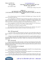
NOTE 1—1 in. = 25.4 mm.
FIG. 1 Gravel Leach Trench
3.2.2 pipe—smooth or corrugated interior wall thermoplastic pipe.
5.4 Fittings recommended by the pipe manufacturer should
be used at all joints and for changes of direction except that
pipe may be bent to a radius of not less than 5 times the
diameter.
4. General Requirements
4.1 Storage—Pipe should be stored with support from a flat
surface to prevent the pipe from developing a permanent set.
5.5 Unless otherwise specified, pipe should be laid true to
grade and aligned in the center of the trench, with the top print
line or location stripe at the 12 o’clock position so that holes
are placed down. It should be held in place by alignment
supports, such as wooden stakes or steel rods.
4.2 Handling—Care should be exercised during loading,
unloading, and in transit because pipe may be damaged by
abrasion and sharp edges. Because thermoplastics are temporarily softened by high temperatures, care should be taken
under these conditions to avoid damage during handling
operations.
NOTE 3—Some authorities require the covering of the line with
untreated building paper or a geotextile to prevent entry of aggregate,
prior to the next step. This is usually required only in areas that require the
perforations to be oriented on the top instead of the bottom of the pipe.
4.3 If contact with chemicals not ordinarily present in
sanitary sewage is anticipated, the approval of the regulatory
authority to install pipe should be obtained.
5.6 For gravel systems, place aggregate around the pipe
until only the top center is still visible. Make a final check of
grade and alignment. It is particularly important that the side
walls be given uniform and continuous support to provide
lateral restraint against deflection during backfilling operations.
Care should be taken to prevent damage to the lines. Do not
permit a dump truck or front-end loader to dump directly over
the pipe. Call for final inspection by local authority if required.
5.6.1 Add additional aggregate until the lines are covered to
a minimum depth of 2 in. (50 mm) above the pipe (see Fig. 1).
Remove alignment supports, level the aggregate, and backfill
to grade with soil. An additional 4 to 6-in. (100 to 150-mm)
overfill is recommended to compensate for settling.
NOTE 1—The manufacturer should be contacted for information on
chemical resistance.
4.4 Coiled pipe is not recommended for use in leach fields
because it is difficult to install at the proper grade and
alignment; it is acceptable with special equipment installation.
NOTE 2—Corrugated interior pipe should not be used between the
dwelling and the waste water treatment unit (septic tank or similar device)
because the corrugations may inhibit the flow of solids contained in the
waste.
5. Installation—Leach Field
NOTE 4—Some authorities require that the top of the aggregate be
protected from migration by a layer of nonbiodegradable, pervious
material such as untreated building paper or a geotextile. Installers should
note that the use of the impervious materials, such as plastic film, prevents
upward evapotranspiration. The governing authority should be contacted
to determine the type of material required.
5.1 Leach fields should be constructed to meet the requirements of the local Department of Health or other governing
authority, which should be contacted for information and
requirements on design, location, installation, materials, and so
forth.
5.7 For the gravel-less leach lines, the plastic protective
covering used in shipping must be removed from the pipe
before backfilling. The geotextile covering of the pipe must be
continuous and not damaged. Gravel-less leach lines should be
backfilled with the soil excavated from the trench. Place
embedment material, free of large particles such as rocks,
clods, and other extraneous materials up to the spring line of
the pipe. Work sufficient material along the sides of the pipe to
provide adequate side support, without compacting the material (see Fig. 2).
5.7.1 Add selected backfill to a minimum of 6 in. (150 mm)
over the top of the pipe. Remaining backfill may consist of
native soil. An additional 4 to 6 in. (100 to 150 mm) of overfill
is recommended to compensate for settling.
5.2 Before installation, pipe should be inspected for damage
such as kinks, crushed portions, splits, and so forth. Any
damaged portions of pipe shall be cut out as a cylinder and
discarded. Make a visual check of the bore to ensure it is clear
of foreign objects that might impede flow.
5.3 Gravel Systems—For proper waste water flow into the
surrounding soils and to provide for support of pipe, a uniform
layer of 4 to 6 in. (100 to 150 mm) of graded aggregate should
be placed in the trench bottom and leveled true to grade prior
to laying the pipe (see Fig. 1). Aggregate should range from 3⁄4
to 21⁄4 in. (13 to 54 mm) in size. The aggregate under the pipe
should not be compacted; for example, by tamping or walking,
as this may damage the soil interface.
2
F481 − 97 (2014)
7. Installation—Curtain Drains
7.1 Curtain drains are installed to prevent water seepage
into a leach field area. They should be installed in accordance
with Practice D2321 or F449 and at least 1 ft (0.3 m) deeper
than the leach lines and 8 to 10 ft (2.4 to 3 m) from the leach
line. The curtain drain should be directed to a free or pump
outlet.
7.2 When perforated, slotted, or slitted pipe is used, gravel
or porous backfill should extend as specified or to any seep
plane (see Fig. 4).
7.3 If edgedrain is used, permeable soil or gravel backfill
may be used (see Fig. 5).
8. Special Precautions
NOTE 1—1 in. = 25.4 mm.
FIG. 2 Gravel-less Leach Trench
8.1 Effect of High Temperatures—Pipe can reach comparatively high temperatures when exposed to the sun and this
reduces the pipe stiffness appreciably. Therefore, precautions
must be taken to prevent the impact of sharp or heavy objects,
the sudden imposition of heavy overburden or excessive pull
on such pipe. The pipe regains full strength and stiffness as the
temperature decreases to that of the soil; this will normally
require about 5 min.
NOTE 5—A record of the installation should be made, including a
dimensional sketch, name of installer, date of installation, type and brand
of pipe installed, and other system details. It is suggested that the system
owner be provided with a copy of this record.
6. Installation—Non-Perforated Pipe
6.1 Non-perforated laterals and connector lines are not
normally bedded in an aggregate envelope but are usually
backfilled with the soil excavated from the trench. Therefore,
place embedment material, free of large particles such as rocks,
clods, and other extraneous materials, up to the spring line of
the pipe and compact by hand or mechanical tamping. Work
sufficient material under the sides of the pipe to provide
adequate side support (see Fig. 3).
8.2 Effect of Low Temperatures—Care in handling and
installation should be exercised under low-temperature conditions to avoid damage. As temperatures decrease, some types
of pipe tend to become more brittle and less flexible.
9. Keywords
9.1 curtain drain; gravel-less; installation; leach field
6.2 Take care to avoid contact between the pipe and
compaction equipment. The initial backfill and backfill material should generally be compacted in such a way that the
compaction equipment is not used directly above the pipe until
sufficient backfill has been placed to ensure that such equipment will not have a damaging effect on the pipe. Refer also to
Practice D2321 or F449 for additional details and definitions.
NOTE 1—1 in. = 25.4 mm.
NOTE 1—1 in. = 25.4 mm.
FIG. 3 Non-Aggregate Installation
FIG. 4 Curtain Drain With Pipe
3
F481 − 97 (2014)
NOTE 1—1 in. = 25.4 mm.
FIG. 5 Curtain Drain With Edgedrain
ASTM International takes no position respecting the validity of any patent rights asserted in connection with any item mentioned
in this standard. Users of this standard are expressly advised that determination of the validity of any such patent rights, and the risk
of infringement of such rights, are entirely their own responsibility.
This standard is subject to revision at any time by the responsible technical committee and must be reviewed every five years and
if not revised, either reapproved or withdrawn. Your comments are invited either for revision of this standard or for additional standards
and should be addressed to ASTM International Headquarters. Your comments will receive careful consideration at a meeting of the
responsible technical committee, which you may attend. If you feel that your comments have not received a fair hearing you should
make your views known to the ASTM Committee on Standards, at the address shown below.
This standard is copyrighted by ASTM International, 100 Barr Harbor Drive, PO Box C700, West Conshohocken, PA 19428-2959,
United States. Individual reprints (single or multiple copies) of this standard may be obtained by contacting ASTM at the above
address or at 610-832-9585 (phone), 610-832-9555 (fax), or (e-mail); or through the ASTM website
(www.astm.org). Permission rights to photocopy the standard may also be secured from the Copyright Clearance Center, 222
Rosewood Drive, Danvers, MA 01923, Tel: (978) 646-2600; />
4