Astm f 2661 07 (2015)
Bạn đang xem bản rút gọn của tài liệu. Xem và tải ngay bản đầy đủ của tài liệu tại đây (198.35 KB, 7 trang )
Designation: F2661 − 07 (Reapproved 2015)
Standard Test Method for
Determining the Tribological Behavior and the Relative
Lifetime of a Fluid Lubricant using the Spiral Orbit
Tribometer1
This standard is issued under the fixed designation F2661; the number immediately following the designation indicates the year of
original adoption or, in the case of revision, the year of last revision. A number in parentheses indicates the year of last reapproval. A
superscript epsilon (´) indicates an editorial change since the last revision or reapproval.
1. Scope
3. Terminology
1.1 This test method covers the quantitative determination
of the friction coefficient and the lifetime of oils and greases,
when tested on a standard specimen under specified conditions
of preparation, speed, Hertzian stress, materials, temperature,
and atmosphere, by means of the Spiral Orbit Tribometer
(SOT). This test method is intended primarily as an evaluation
of the lifetimes of fluid lubricants under vacuum and ambient
conditions.
1.2 This standard may involve hazardous materials,
operations, and equipment. This standard does not purport to
address all of the safety concerns, if any, associated with its
use. It is the responsibility of the user of this standard to
establish appropriate safety and health practices and to
determine the applicability of regulatory limitations prior to
use.
3.1 Definitions:
3.1.1 coeffıcient of friction—the dimensionless ratio of the
friction force between two bodies to the normal force pressing
these bodies together.
3.1.2 fixed plate—stationary, horizontal flat plate, typically
through which a force (the “load”) is applied to the ball.
3.1.3 friction coeffıcient limit—maximum value that the
friction coefficient is permitted to attain.
3.1.4 guide plate—physical element that deflects the ball to
its original orbit radius.
3.1.5 lubricant total amount— mass of lubricant deposited
on the entire ball surface at the beginning of the test.
3.1.6 normalized lifetime—number of ball orbits performed
until the friction coefficient limit is reached divided by the
lubricant total amount initially deposited on the ball.
3.1.7 rotary plate—flat plate rotating at a constant rate
selected for the test.
3.1.8 scrub zone—Region of the ball’s orbit in which the
ball is in contact with the guide plate.
3.1.9 spiral orbit—track traced by the ball on the fixed and
rotating plates of the Spiral Orbit Tribometer. The track has a
spiral shape.
2. Referenced Documents
2.1 ASTM Standards:2
D1193 Specification for Reagent Water
F22 Test Method for Hydrophobic Surface Films by the
Water-Break Test
F2215 Specification for Balls, Bearings, Ferrous and Nonferrous for Use in Bearings, Valves, and Bearing Applications
G115 Guide for Measuring and Reporting Friction Coefficients
2.2 Anti Friction Bearing Manufacturers Association Standards3
ANSI ABMA ISO 3290 (AFBMA Standard 10 Balls)
4. Summary of Test Method
4.1 A lubricated ball is clamped between two parallel plates.
One of the plates rotates up to 210 rpm, causing the ball to roll
in a near-circular orbit, but is actually an opening spiral. A
clamping force, the “load”, provides a chosen mean Hertz
stress (typically 1.5 GPa). The system is targeted to operate in
the boundary lubrication regime due to the combination of the
high load, the moderate speed, and the small amount of
lubricant (approximately 50 µg). The ball rolls and pivots in a
spiral orbit and is maintained in the orbit by the guide plate.
The ball slides on the rotating plate when it contacts the guide
plate. The measured force exerted by the ball on the guide plate
is used to determine the friction coefficient. The tribometer
runs until the coefficient of friction rises to values much larger
than the initial, steady value. At this point the initial charge of
1
This test method is under the jurisdiction of ASTM CommitteeF34 on Rolling
Element Bearings and is the direct responsibility of Subcommittee F34.02 on
Tribology.
Current edition approved April 1, 2015. Published July 2015. Originally
approved in 2007. Last previous edition approved in 2007 as F2661–07. DOI:
10.1520/F2661-07R15.
2
For referenced ASTM standards, visit the ASTM website, www.astm.org, or
contact ASTM Customer Service at For Annual Book of ASTM
Standards volume information, refer to the standard’s Document Summary page on
the ASTM website.
3
Available from American Bearing Manufacturers Association (ABMA), 8221
Old Courthouse Road, Suite 207 Vienna, Virginia 22182.
Copyright © ASTM International, 100 Barr Harbor Drive, PO Box C700, West Conshohocken, PA 19428-2959. United States
1
F2661 − 07 (2015)
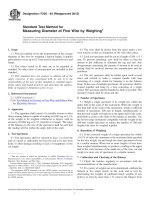
6.1.1 General description—Fig. 3 shows a schematic drawing of a typical SOT. The system consists of a lubricated ball
rolling and pivoting between a fixed plate and a rotary plate.
The load is applied through the fixed plate. The track is a spiral
and the ball is returned to its original orbit radius by contacting
the guide plate, which forces the ball to return to its original
radius each orbit. The friction coefficient is determined by the
measuring the force on the guide plate when the ball contacts
the guide plate. A piezoelectric force transducer is attached to
the guide plate. This force, divided by twice the normal load,
is the friction coefficient.
6.1.2 Motor drive— A variable speed motor, capable of
constant speed, is required. Rotating plate speeds are typically
in the range 1 to 210 rpm (0.10 to 22 rad.s − 1). The effective
stiffness of the axis shall be at least 1.8 E +05 Newton/meter
axial in the load direction, 3.6 E +08 Newton/meter radial and
1.13 E +05 Newton-meter/Radian moment. The TIR of the
motor shaft shall be 0.0254 millimeters maximum.
6.1.3 Fixed load plate— The load plate shall have an axial
stiffness of at least 1.8 E +08 Newton/meter in the load
direction. The effective radial stiffness of the plate axis shall be
at least1.8 E+08 Newton/meter and the moment stiffness shall
be at least 1.13 E +05 Newton-meter/Radian.
6.1.4 Orbit counter— The SOT shall be equipped with a
revolution counter or its equivalent that will record the number
of ball orbits. The tribometer would preferably have the ability
to shut off after a pre-selected number of orbits or friction
coefficient has been reached.
6.1.5 Applied load— The fixed plate is attached to a system
to apply the load, up to 222.5 N (50 lb.), providing the desired
Hertzian stress, typically 1.5 GPa.
6.1.6 The instruments and gauges:
6.1.6.1 Friction force— The friction coefficient is determined by measuring the force on the guide plate while the ball
contacts the guide plate. This force is measured using a
piezoelectric force transducer and a charge amplifier. The
friction force and the coefficient of friction can then be
lubricant has been depleted by tribodegradation and the system
is running virtually unlubricated. The normalized lifetime is
obtained from the number of spiral orbits completed before
reaching the chosen friction coefficient limit divided by the
total lubricant mass on the ball at the beginning of the test. A
minimum of four tests per lubricant and test condition shall be
performed. Lubricants can be compared by calculating their
average normalized lifetimes for a given set of test conditions.
5. Significance and Use
5.1 Relevance of the Spiral Orbit Tribometer (SOT)—The
SOT was designed to evaluate the relative degradation rates of
liquid lubricants in a contact environment similar to that in an
angular contact bearing operating in the boundary lubrication
regime. It functions as a screening device to quickly select the
lubricants, evaluate the ability of various components of a
lubricant (base oil, thickener, or additive) to lubricate a contact
in rolling, pivoting, and sliding conditions simultaneously, and
study their chemical decomposition if necessary. The SOT
provides a means to study the tribological behavior of oils and
greases during operation, while they undergo changes as a
function of typical parameters encountered in the lubrication
field (temperature, environment, materials used, load applied,
and speed). Test conclusion is defined to be when a friction
coefficient limit (typically an increase of 0.1 above the steady
state value) is surpassed. Normalized lubricant lifetime is then
defined as the number of orbits completed divided by the initial
amount of lubricant used (in µg). The SOT was initially
developed to evaluate lubricants for space applications, but is
also relevant for conventional environments. Some results in
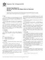
vacuum are presented (Fig. 1). At this time, no data for tests in
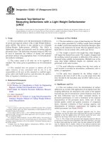
ambient conditions have been published (see Fig. 2). The user
of this test method should determine to their own satisfaction
whether results of this test procedure correlate with field
performance or other bench test procedures.
6. Apparatus
6.1 The Spiral Orbit Tribometer (SOT)—See Fig. 3.
Pepper, S.V., Kingsbury, E.P., “Spiral Orbit Tribometry – Part II: Evaluation of Three Liquid Lubricants in Vacuum”, Tribo. Trans., V 46, 1, pp 65-69, 2003
FIG. 1 Relative lifetimes of three typical space lubricants at 23°C in vacuum on 52100 steel
2
F2661 − 07 (2015)
Bazinet, D.G., Espinosa, M.A., Loewenthal, S.H., Gschwender, L., Jones, W.R., Jr., Predmore, R.E., “Life of Scanner Bearings with Four Space Liquid Lubricants”, Proc.
37th Aerospace Mech. Symp., Johnson Space Center, May 19-21, 2004
FIG. 2 Comparison between full scale bearing tests** and SOT data at 23°C on 440C steel.
FIG. 3 Detail of the Spiral Orbit Tribometer
obtained as explained in Section 11. The load cell shall be
linear to within 2 % across the entire temperature range of the
test.
6.1.6.2 Environment— The SOT operates in either one
atmosphere air, under a cover gas, or vacuum. When operating
under vacuum or ultrahigh vacuum, a cold cathode pressure
gauge attached to the chamber monitors the pressure. A hot
cathode gauge should be avoided since electrons from the
filament could alter lubricant chemistry. It is the responsibility
of the user to determine the chemical purity of the environment
and gas to establish the contribution to tribochemistry.
6.1.6.3 Measurement of the temperature —When a controlled temperature is required, the temperature is monitored
using a thermocouple (for example, K-type) attached to the
stationary disk during the test.
7. Reagents and Materials
7.1 Balls, plates, guide plates. Typical instrument bearing
materials may be of 440C material, but other materials may be
used to simulate the bearing application.
7.1.1 Test balls—Test balls shall be 12.7 mm (0.5 inch)
diameter, grade 25 or better, made with 440C stainless steel.
3
F2661 − 07 (2015)
such as Test Method F22 using reagent grade water per
Specification D1193, or a wettability test using the intended
oil. Since many variations of cleaning methods exist and their
results may have a strong effect on the results, it is the user’s
responsibility to determine the effectiveness and safety of the
cleaning methods. The details of the cleaning methods shall
described in the test report.
Their recommended Rockwell hardness shall be 58 to 62. See
Specification F2215 or ANSI ABMA ISO 3290 (AFBMA
Standard 10) for ball specification reference. Other materials
may be used to simulate specific application chemistry.
7.1.2 Plates, Guide plates—The fixed plate and the rotary
plate are disks of 50.8 mm (2 inch) in diameter, may be made
with 440C stainless steel, or any desired material. Surface
roughness of 0.05 mm average roughness or less is recommended. The guide plates are small cylinders 12.7 mm (0.5
inch in diameter), with a polished surface of 0.05 mm average
roughness or less (recommended). The recommended Rockwell hardness for 440C shall be 58 to 62. Stationary and rotary
plates should be made with the same material. Any bearing
material can be used, depending on the application being
simulated. The recommended values should be used unless
differences are required to simulate a specific application.
7.1.3 Care must be taken in surface preparation and handling to avoid surface damage or contamination after cleaning
that alters the material. Typical cleaning methods may be used
when the results will pass an Test Method F22 standard test for
wetability and do not damage the materials or adversely alter
the sample surfaces. A wettability test using the intended
lubricant to evaluate the ball and plate cleaning method is
recommended.
7.1.4 Reagent grade chemicals shall be used per Test
Method F22 section 8.1. It is the user’s responsibility to
prevent contamination or adulteration of the lubricant samples,
and prevent materials used to clean or lubricate from harming
the samples.
10.2 Lubrication of the balls—Lubrication of the test system
is to the ball only. The objective is to lubricate the balls with a
small and controlled amount of lubricant. The target amount is
as close as possible to 50 +/− 2 µg for a 12.7 mm diameter ball.
10.2.1 Lubrication of the balls with oil:
10.2.1.1 Preparation of a dilute solution of oil:
(1) Choose a solvent suitable for the oil to be tested. The
user must determine that the solvent does not harm the sample
surface or alter the lubricant.
(2) Weigh a clean, dry and empty bottle.
(3) Put a small drop of oil within the bottle.
(4) Note the mass of oil (moil) in milligrams.
(5) Add a volume of solvent in the bottle to obtain the
proportion of one milliliter of solvent per one milligram of oil.
(6) Close the bottle and shake it to create an homogeneous
solution.
It is the responsibility of the user to determine the type of
solvent used. Some solvents may not produce a homogeneous
solution and can have an adverse effect on the results. Care
must be taken to produce a final lubricant film that is
unadulterated on the ball.
10.2.1.2 Lubrication of the ball:
(1) Weigh a dry, clean ball with a micro-balance to 62 µg.
(2) Fill a micro-syringe with the dilute oil solution.
(3) Attach the ball to a handling tool that spins the ball and
start the ball spinning.
(4) Put fifty microliters, drop by drop, of the dilute solution
on the surface of the spinning ball.
(5) Wait at least five minutes or until the weight of the
sample is stable to allow the solvent to evaporate.
(6) Remove the ball from the spinning device.
(7) Weigh the lubricated ball with a micro-balance to 62
µg.
(8) Determine the amount of oil, in µg, on the ball and
record.This procedure has to be done for the minimum four
balls used to test the oil sample. To avoid contamination, it is
recommended that each ball be lubricated just prior the start of
each test.
10.2.2 Lubrication of the balls with grease:
10.2.2.1 Preparation of the material:
(1) Cut six 5 cm2 squares in a polyethylene sheet.
(2) Attach each square on the top of a beaker with a rubber
band.
(3) Make sure the polyethylene squares are forming an
elastic membrane.
(4) Clean each square surface with a clean room wipe and
IPA, followed with a flush of clean IPA
(5) Dry each square surface with clean dry air or nitrogen
and take precautions to prevent a buildup of a static charge and
the attraction of particulate or lint.
10.2.2.2 Lubrication of the ball:
8. Hazards
8.1 Use of solvents— Operator will refer to the safety data
sheet of all the solvents used and will take appropriate
precautions.
8.2 Use of ultrasonic cleaning systems (if applicable)—
Operator will refer to the instruction manual of the ultrasonic
bath before use.
8.3 Use of ultra violet (U.V.)/ozone cleaning system (if
applicable)—Operator will refer to the instruction manual of
the U.V./ozone cleaning system before use. Special care will be
taken to check the compatibility of the materials used to a U.V.
and ozone exposure.
8.4 Ultrahigh vacuum chamber (if applicable)—The
vacuum chamber will be operated with appropriate copper or
elastomer seals to reach ultrahigh vacuum, and will not be
opened until the inside of the chamber has reached atmospheric
pressure.
9. Sampling, Test Specimens, and Test Units
9.1 Test specimens— Specimens (plates, balls, guide plates)
will be kept for further analysis, if required.
9.2 Test units—Only SI units will be used.
10. Procedure
10.1 Cleaning of the parts and tools may be any method that
simulates the application. It is recommended that the results of
cleaning procedures are tested using a water break free test
4
F2661 − 07 (2015)
(1) Weigh a dry, clean ball with a microbalance to 62 µg.
(2) Put a very small amount of grease on the ball (less then
1 mm3).
(3) Place the ball between two polyethylene squares fixed
to the beakers.
(4) Roll the ball for one minute between the two polyethylene squares.
(5) Place the ball between the second set of two polyethylene squares fixed to the beakers.
(6) Roll the ball for 30 seconds on the two polyethylene
squares.
(7) Place the ball between the third set of polyethylene
squares fixed to the beakers.
(8) Roll the ball for 15 seconds between the two polyethylene squares.
(9) Weigh the lubricated ball with a microbalance to 62 µg.
(10) Determine the amount of grease, in µg, on the ball.
The consistency varies from grease to grease. In some cases,
the amount of grease is too much or too little. The operator will
again need to roll the ball between one or all the sets of
polyethylene squares until the appropriate amount of grease is
reached. The goal is to apply as near to 50 µg as possible.
This procedure has to be done for the minimum of four balls
used to test the grease sample. To avoid contamination, it is
recommended that each ball be lubricated just prior the start of
each test.
(6) Remove the guide plate from the holder.
(7) Place the guide plate on its dedicated holder.
(8) Place a new guide plate on the guide plate holder.
(9) Place a 1 mm thick washer on the screw of the force
transducer to advance the position of the guide plate, establishing a new track on the fixed and rotary plates. If more than
4 tests are to be performed, a fresh set of plates should be used
to prevent a reduction in the diameter of the spiral beyond 4
tests.
(10) Tighten the guide plate holder with its guide plate to
the force transducer
(11) Place a new lubricated ball with pristine lubricant on
the lower plate and in contact with the guide plate.
(12) Apply the selected load for the test.
(13) Rotate the rotary plate so as there is not contact
between the guide plate and the ball.
(14) Ground the piezoelectric charge amplifier.
(15) Close the door of the SOT.
(16) Start the roughing and turbomolecular pumps.
(17) Turn on the pressure gauge.
(18) Wait until the pressure drops below 1.3E-6 Pa if the
test is a vacuum test.
(19) Start the test.
(20) When the test is finished, record the number of orbits
performed.
(21) Calculate the normalized lifetime.
10.3 Assembly of the Spiral Orbit Tribometer:
10.3.1 Test under vacuum or appropriate atmosphere at
room temperature
10.3.1.1 First test:
(1) Open the door of the SOT.
(2) Fix the upper disk.
(3) Fix the lower disk
(4)Attach the guide plate to its holder.
(5) Tighten the guide plate holder with its guide plate to the
force transducer.
(6) Place the ball on the lower plate and in contact with the
guide plate.
(7) Apply the selected load for the test.
(8) Rotate the rotary plate so as there is no contact between
the guide plate and the ball.
(9) Close the door of the SOT.
(10) Set the speed of the test with the motor controller.
(11) Start the roughing and turbomolecular pumps.
(12) Turn on the pressure gauge.
(13) Wait until the pressure drops below 1.3E-6 Pa if the
test is a vacuum test.
(14) Start the test.
(15) When the test is finished, write down the number of
orbits performed.
(16) Calculate the normalized lifetime.
10.3.1.2 Second and sequential tests.
(1) Open the door of the SOT.
(2) Unload the system.
(3) Remove the ball.
(4) Place the ball on a handling tool.
(5) Remove the guide plate holder from the force transducer.
10.4 Data collection and treatment—The SOT should be
interfaced to a data acquisition computer to continuously
record several parameters, such as the friction coefficient, the
load applied, the pressure within the vacuum chamber (if
applicable), the temperature (if applicable), and the resistance
across the ball-disks contacts (optional). This data can be
stored in a file, and one file can be created for each test.
11. Calculation or Interpretation of Results
11.1 Friction Coeffıcient
Coefficient of Friction 5 C o F 5
F gp
2 3 load
(1)
where:
Fgp = force exerted by the ball on the guide plate, and
measured by the force transducer attached to the
guide plate.
load = load applied between the plates to maintain the ball
between them.
11.2 Normalized Lifetime—The normalized lifetime for one
test of a lubricant is obtained by calculating the number of
orbits performed before the friction coefficient limit is reached
divided by the total amount of lubricant put on the ball (in µg)
at the beginning of the test. An average is made over a
minimum of four normalized lifetimes obtained after running
four tests for the lubricant to be evaluated. More sample tests
may be run to eliminate outliers and to determine the standard
deviation in the performance of the samples.
12. Report
12.1 The following data should be included in the test
report:
5
F2661 − 07 (2015)
12.1.1 The type of lubricant evaluated.
12.1.2 The amount (in µg) of the lubricant deposited on the
ball, and the technique used to lubricate the ball.
12.1.3 The materials of the fixed plate, rotary plate, ball,
guide plate used and the technique used to clean them. The
surface roughness, hardness and condition such as passivation
if applicable.
12.1.4 The atmosphere the test was run in, the temperature
of the test, the load applied, the speed.
12.1.5 The initial steady state friction coefficient, the total
number of orbits performed, the cut-off friction coefficient, the
normalized lifetime, and the standard deviation obtained.
have produced coefficient of variation of 30 % or less for
normalized lifetime on the SOT (See Fig. 1).
13.2 Friction coefficients of material couples obtained on
the SOT may be different from coefficients of the same
material couples tested on a different apparatus. A friction
coefficient is a system effect, so appropriate caution must be
used when comparing or using data from different sources and
systems.
13.3 This is an interim standard and precision and bias data
have not been collected or reported. An effort to construct a
standard test and collect inter-laboratory data is underway.
12.2 Two charts should be plotted in the test report:
12.2.1 The first chart will include the friction traces of the
tests conducted for the lubricant.
12.2.2 The second chart will be the average normalized
lifetime of the lubricant with its standard deviation.
14. Keywords
14.1 accelerated testing; boundary lubrication; fluid lubricants; friction coefficient; greases; tribology; relative lifetimes;
vacuum tribology
13. Precision and Bias
13.1 Normalized lifetime—Experiments have shown that
carefully conducted tests with lubricants of a different nature
ANNEX
(Mandatory Information)
A1. MEASUREMENT OF FRICTION COEFFICIENT
A1.1 The following analysis is from S. V. Pepper and E. P.
Kingsbury.4 This paper describes how the SOT measures the
friction coefficient from the force experienced by the guide
plate normal to its face. For this, expressions for the ball’s
angular velocity during both the spiral orbit and the scrub zone
were developed. The analysis determines the locus of slip
between the ball and plates and ultimately indicates the
relationship between the friction coefficient and the guide plate
force. The analysis is based on roll without slip between rigid
bodies, meaning no relative linear velocity exists at the
ball-plate contact. This is required because rolling friction is an
order of magnitude smaller than sliding friction, even for the
most favorable boundary lubricated conditions. The roll without slip condition is satisfied at all contacts in the system
except between the ball and the rotating plate in the scrub
region. This contact in the scrub between the ball and the
rotating plate exhibits gross sliding. The analysis shows that
the force on the guide plate, normal to its face, is twice the
friction force generated by the ball sliding on the rotating plate.
This establishes the ability of the SOT to measure the friction
force by the transducer on which the guide plate is mounted.
The coefficient of friction (CoF) is then obtained by dividing
this friction force by the load:
C oF 5
F gp
2 3 load
(A1.1)
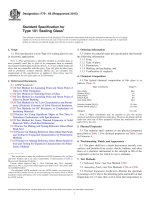
A plot of the guide plate force versus time of the ball in the
scrub is shown in Fig. A1.1. The guide plate force has already
been divided by 2 to obtain the friction force indicated on the
ordinate. The region in which the friction force is obtained for
the calculation of the CoF is indicated by the heavy horizontal
bar. This procedure is explained in the reference cited above.
4
S. V. Pepper and E. P. Kingsbury, “Spiral Orbit Tribometry – Part II: Evaluation
of Three Liquid Lubricants in Vacuum,” Trib. Trans. 46,57(2003).
FIG. A1.1 Typical guide plate force profile from the SOT
6
F2661 − 07 (2015)
A1.2 The friction is measured only during ; 5 % of the
orbit traversed by the ball. There may also be forces on all the
elements that are tangential to the guide plate’s face. However,
the force transducer only senses forces normal to the guide
plate’s face, so that forces tangential to the guide plate’s face
are not considered further here.
ASTM International takes no position respecting the validity of any patent rights asserted in connection with any item mentioned
in this standard. Users of this standard are expressly advised that determination of the validity of any such patent rights, and the risk
of infringement of such rights, are entirely their own responsibility.
This standard is subject to revision at any time by the responsible technical committee and must be reviewed every five years and
if not revised, either reapproved or withdrawn. Your comments are invited either for revision of this standard or for additional standards
and should be addressed to ASTM International Headquarters. Your comments will receive careful consideration at a meeting of the
responsible technical committee, which you may attend. If you feel that your comments have not received a fair hearing you should
make your views known to the ASTM Committee on Standards, at the address shown below.
This standard is copyrighted by ASTM International, 100 Barr Harbor Drive, PO Box C700, West Conshohocken, PA 19428-2959,
United States. Individual reprints (single or multiple copies) of this standard may be obtained by contacting ASTM at the above
address or at 610-832-9585 (phone), 610-832-9555 (fax), or (e-mail); or through the ASTM website
(www.astm.org). Permission rights to photocopy the standard may also be secured from the Copyright Clearance Center, 222
Rosewood Drive, Danvers, MA 01923, Tel: (978) 646-2600; />
7