Astm g 76 13
Bạn đang xem bản rút gọn của tài liệu. Xem và tải ngay bản đầy đủ của tài liệu tại đây (259.23 KB, 6 trang )
Designation: G76 − 13
Standard Test Method for
Conducting Erosion Tests by Solid Particle Impingement
Using Gas Jets1
This standard is issued under the fixed designation G76; the number immediately following the designation indicates the year of original
adoption or, in the case of revision, the year of last revision. A number in parentheses indicates the year of last reapproval. A superscript
epsilon (´) indicates an editorial change since the last revision or reapproval.
G40 Terminology Relating to Wear and Erosion
2.2 American National Standard:
ANSI B74.10 Grading of Abrasive Microgrits4
1. Scope
1.1 This test method covers the determination of material
loss by gas-entrained solid particle impingement erosion with
jetnozzle type erosion equipment. This test method may be
used in the laboratory to measure the solid particle erosion of
different materials and has been used as a screening test for
ranking solid particle erosion rates of materials in simulated
service environments (1, 2).2 Actual erosion service involves
particle sizes, velocities, attack angles, environments, and so
forth, that will vary over a wide range (3-5). Hence, any single
laboratory test may not be sufficient to evaluate expected
service performance. This test method describes one well
characterized procedure for solid particle impingement erosion
measurement for which interlaboratory test results are available.
3. Terminology
3.1 Definitions:
3.1.1 erosion—progressive loss of original material from a
solid surface due to mechanical interaction between that
surface and a fluid, a multicomponent fluid, or impinging liquid
or solid particles.
3.1.2 impingement—a process resulting in a continuing
succession of impacts between (liquid or solid) particles and a
solid surface.
3.2 Definitions of Terms Specific to This Standard:
3.2.1 erosion value—the volume loss of specimen material
divided by the total mass of abrasive particles that impacted the
specimen (mm3·g−1).
3.2.2 Normalized Erosion Rate—erosion value (mm3·g−1) of
specimen material divided by erosion value (mm3·g−1) of
reference material.
1.2 Units—The values stated in SI units are to be regarded
as standard. No other units of measurement are included in this
standard (exceptions below).
1.2.1 Exceptions: Table 1 uses HRB hardness. Footnote 7
and 11.2 use abrasive grit designations.
1.3 This standard does not purport to address all of the
safety concerns, if any, associated with its use. It is the
responsibility of the user of this standard to establish appropriate safety and health practices and determine the applicability of regulatory limitations prior to use.
4. Summary of Test Method
4.1 This test method utilizes a repeated impact erosion
approach involving a small nozzle delivering a stream of gas
containing abrasive particles which impacts the surface of a
test specimen. A standard set of test conditions is described.
However, deviations from some of the standard conditions are
permitted if described thoroughly. This allows for laboratory
scale erosion measurements under a range of conditions. Test
methods are described for preparing the specimens, conducting
the erosion exposure, and reporting the results.
2. Referenced Documents
2.1 ASTM Standards:3
E122 Practice for Calculating Sample Size to Estimate, With
Specified Precision, the Average for a Characteristic of a
Lot or Process
5. Significance and Use
1
This test method is under the jurisdiction of ASTM Committee G02 on Wear
and Erosion and is the direct responsibility of Subcommittee G02.10 on Erosion by
Solids and Liquids.
Current edition approved July 1, 2013. Published July 2013. Originally approved
in 1983. Last previous edition approved in 2007 as G76–07. DOI: 10.1520/G007613.
2
The boldface numbers in parentheses refer to a list of references at the end of
this standard.
3
For referenced ASTM standards, visit the ASTM website, www.astm.org, or
contact ASTM Customer Service at For Annual Book of ASTM
Standards volume information, refer to the standard’s Document Summary page on
the ASTM website.
5.1 The significance of this test method in any overall
measurements program to assess the erosion behavior of
materials will depend on many factors concerning the conditions of service applications. The users of this test method
should determine the degree of correlation of the results
4
Available from American National Standards Institute (ANSI), 25 W. 43rd St.,
4th Floor, New York, NY 10036.
Copyright © ASTM International, 100 Barr Harbor Drive, PO Box C700, West Conshohocken, PA 19428-2959. United States
1
G76 − 13
TABLE 1 Characteristics of Type 1020 Steel Reference Material
Annealed 900 s at 760°C, air cooled.
Hardness: HRB = 70 ± 2.
Chemical Composition:
C = 0.20 ± 0.01 wt %
Mn = 0.45 ± 0.10
S = 0.03 ± 0.01
Si = 0.1± 0.05
P = 0.01 ± 0.01
obtained with those from field performance or results using
other test systems and methods. This test method may be used
to rank the erosion resistance of materials under the specified
conditions of testing.
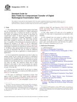
FIG. 1 Schematic Drawing of Solid Particle Erosion Equipment
6. Apparatus
7.2 The abrasive material to be used shall be uniform in
essential characteristics such as particle size, moisture, chemical composition, and so forth.
6.1 The apparatus is capable of eroding material from a test
specimen under well controlled exposure conditions. A schematic drawing of the exit nozzle and the particle-gas supply
system is shown in Fig. 1. Deviations from this design are
permitted; however, adequate system characterization and
control of critical parameters are required. Deviations in nozzle
design and dimensions must be documented. Nozzle length to
diameter ratio should be 25:1 or greater in order to achieve an
acceptable particle velocity distribution in the stream. The
recommended nozzle5 consists of a tube about 1.5 mm inner
diameter, 50 mm long, manufactured from an erosion resistant
material such as WC, A12O3, and so forth. Erosion of the
nozzle during service shall be monitored and shall not exceed
10 % increase in the initial diameter.
7.3 Sampling of material for the purpose of obtaining
representative test specimens shall be done in accordance with
acceptable statistical practice. Practice E122 shall be consulted.
8. Calibration of Apparatus
8.1 Specimens fabricated from Type 1020 steel (see Table 1
and Fig. 2) equivalent to that used in the interlaboratory test
series6 shall be tested periodically using specified (see Section
9) 50 µm A12O3 particles to verify the satisfactory performance
of the apparatus. It is recommended that performance be
verified using this reference material every 50 tests during a
measurement series, and also at the beginning of each new test
series whenever the apparatus has been idle for some time. The
recommended composition, heat treatment, and hardness range
for this steel are listed in Table 1. The use of a steel of different
composition may lead to different erosion results. A photomicrograph of the specified A12O3 particles is shown in Fig. 3.
The range of erosion results to be expected for this steel under
the standard test conditions specified in Section 9 is shown in
Table 2 and is based on interlaboratory test results.6
6.2 Necessary features of the apparatus shall include a
means of controlling and adjusting the particle impact velocity,
particle flux, and the specimen location and orientation relative
to the impinging stream.
6.3 Various means can be provided for introducing particles
into the gas stream, including a vibrator-controlled hopper or a
screw-feed system. It is required that the system provide a
uniform particle feed and that it be adjustable to accommodate
desired particle flow values.
8.2 Calibration at standard test conditions is recommended
even if the apparatus is operated at other test conditions.
6.4 A method to measure the particle velocity shall be
available for use with the erosion equipment (6-9). Examples
of accepted methods are high-speed photography (7), rotating
double-disk (6), (8), and laser velocimeter (9). Particle velocity
shall be measured at the location to be occupied by the
specimen and under the conditions of the test.
8.3 In any test program the particle velocity and particle
feed rate shall be measured at frequent intervals, typically
every ten tests, to ensure constancy of conditions.
9. Standard Test Conditions
9.1 This test method defines the following standard conditions.
9.1.1 The nozzle tube shall be 1.5 mm 6 0.075 mm inner
diameter at least 50 mm long.
9.1.2 The test gas shall be nominally dry air. The test report
shall indicate the amount of water present in the test gas, at
what pressure, and how the measurement was conducted.
7. Test Materials and Sampling
7.1 This test method can be used over a range of specimen
sizes and configurations. One convenient specimen configuration is a rectangular strip approximately 10 by 30 by 2 mm
thick. Larger specimens and other shapes can be used where
necessary, but must be documented.
NOTE 1—In the interlaboratory testing, one laboratory utilized cylindertype compressed air having a water content amount described as “-50°C
dew point” by the manufacturer. Whatever gas source is used in testing, a
5
The sole source of supply of the recommended nozzle (tungsten carbide)
known to the committee at this time is Kennametal Inc., 1600 Technology Way, PO
Box 231, Latrobe, PA 15650-0231. If you are aware of alternative suppliers, please
provide this information to ASTM International Headquarters. Your comments will
receive careful consideration at a meeting of the responsible technical committee,1
which you may attend.
6
Supporting data have been filed at ASTM International Headquarters and may
be obtained by requesting Research Report RR:G02-1003.
2
G76 − 13
FIG. 4 Example of Erosion Crater Profile for 1020 Steel Eroded
at 70 m/s Particle Velocity Using Standard Conditions Otherwise
9.1.3 The abrasive particles shall be nominal 50-µm angular
A12O3,7 equivalent to those used in the interlaboratory test
series (see Fig. 3). Abrasive shall be used only once.
NOTE 2—Typical size distribution (determined by sedimentation):
100 % between 20 to 83 µm, 50 % between 42 to 57 µm, 50 % coarser
than 48 µm.
FIG. 2 Microstructure of 1020 Steel Reference Material
ASTM Grain Size 9
9.1.4 The abrasive particle velocity shall be 30 6 2 m·s−1,
measured at the specimen location. At this velocity the gas flow
rate will be approximately 0.13 L/s and the system pressure
will be approximately 140 kPa although the pressure will
depend on the specific system design.
9.1.5 The test time shall be 600 s to achieve steady state
conditions. Longer times are permissible so long as the final
erosion crater is no deeper than 1 mm.
9.1.6 The angle between the nozzle axis and the specimen
surface shall be 90 6 2°.
9.1.7 The test temperature shall be the normal ambient
value (typically between 18°C to 28°C).
9.1.8 The particle feed rate shall be 0.033 6 0.008 g/s. This
corresponds to a particle flux at the specimen surface of about
2 mg·mm−2·s−1 under standard conditions. Particle flux determination requires measurement of the eroded area on the
specimen and is subject to considerable error. A measured
width and depth profile of an erosion crater produced using
stated conditions is shown in Fig. 4 and indicates a typical
eroded width/depth relation.
9.1.9 The distance from specimen surface to nozzle end
shall be 10 6 1 mm.
10. Optional Test Conditions
10.1 When test conditions or materials other than those
given in Section 9 are used, reference to this test method shall
FIG. 3 Photomicrograph of 50 µm A12O3 Particles Used in Interlaboratory Testing
7
The sole source of supply of the aluminum oxide particles—obtained as grade
240-grit alundum powder— known to the committee at this time is Norton Co., 1
New Bond St, Worcester, MA 01606. If you are aware of alternative suppliers,
please provide this information to ASTM International Headquarters. Your comments will receive careful consideration at a meeting of the responsible technical
committee,1 which you may attend.
comparable level of dryness to that is recommended.
3
G76 − 13
clearly specify all test conditions and materials. It should be
noted that other conditions, for example, larger particle
velocities, may adversely affect measurement precision.
11. Test Procedure
11.1 Establish and measure the particle velocity and particle
flow specified. Adjust equipment controls to obtain proper
velocity and flow conditions before inserting test specimens.
Particle flow rate values are determined by collecting (see Note
3) and subsequently weighing the abrasive exiting from the
nozzle for a measured time period.
NOTE 3—Particles may be collected by directing the flow from the
nozzle into a large vented container. Care must be taken to avoid causing
any significant back pressure on the nozzle as this will disturb the system
flow conditions.
11.2 Prepare the specimen surface if required to achieve
uniformity and adequate finish. Grinding through a series of
abrasive papers to 400 grit is usually adequate so long as all
surface scale is removed. A surface roughness of 1 µm (40 µin.)
rms or smaller is recommended. Clean the specimen surface
carefully (see Note 4). Weigh on an analytical balance to
60.01 mg (see Note 5).
NOTE 4—Important considerations in cleaning include surface oils or
greases, surface rust or corrosion, adhering abrasive particles, etc.
NOTE 5—Erosion weight loss determinations to 60.1 mg may be
sufficient for particle velocities above 70 m·s−1 or sufficiently long
exposure times which lead to weight losses greater than 10 mg.
FIG. 5 Two Examples of Erosion versus Time for Type 1020 Steel
at 30 m·s−1 and 70 m·s−1
12.1.2 Specimens: method of preparing and cleaning
specimens, initial surface roughness, and number tested.
12.1.3 Eroding particle identification: size distribution,
shape, composition, purity, source, and manufacturing method.
Provide photograph of typical collection of particles. Reference (10) can be consulted for information on methods of
characterization.
12.1.4 Test conditions: particle velocity (average) and
method of determination; specimen orientation relative to the
impinging stream; particle flow; particle flux; eroded area
(size, shape); temperature of the specimen and particles and
carrier gas; test duration; method of determining steady-state
erosion conditions; carrier gas composition, including water
content, pressure, and measurement method; and method of
determining the mass of abrasive used.
12.1.5 Description of the test equipment.
12.1.6 Tabulation of erosion value and standard deviation
for each specimen reported as a volume loss of material per
unit mass of abrasive (mm3·g−1).
11.3 Mount the specimen in proper location and orientation
in the apparatus. Subject the specimen to particle impingement
for a selected time interval, measured to an accuracy of 5 s.
Remove the specimen, clean carefully (see Note 4), reweigh
and calculate the mass loss.
11.4 Repeat this process utilizing a new specimen each time
to determine at least four points for a total time of at least 600
s and plot those values as mass loss versus elapsed time.
Suitable times would be 120, 240, 480, and 960 s for a material
such as Type 1020 steel. Steady state erosion should result after
60 to 120 s, depending on the material. Two examples of
measured erosion versus time curves are shown in Fig. 5.
11.5 The steady state erosion rate (see Terminology G40) is
determined from the slope of the mass loss versus time plot.
The average erosion value is calculated by dividing erosion
rate (mg/s) by the abrasive flow rate (g/s) and then dividing by
the specimen density (g·cm−3). Report the average erosion
value as (mm3·g−1).
12.2 Each test program shall include among the materials
tested a reference material tested under the same conditions to
permit calculation and report of the normalized erosion rate. A
suitable reference material would be Type 1020 steel (see Table
1).
11.6 Repeat 11.1 at the end of a series of tests (typically
every 10 tests) and more frequently if necessary.
12. Report
12.1 The test report shall include the following information:
12.1.1 Material identification: type, chemical specification,
heat and processing treatment, hardness, and density. Processing conditions shall include method of casting (such as chill or
sand); method of forming (such as forging or pressing and
sintering); and the percent of ideal density (important for
ceramics and powder metallurgy alloys).
12.3 The report shall state clearly whether testing was done
at standard conditions, shall itemize any deviations from those
conditions, and shall indicate the frequency of calibration using
reference materials.
12.4 Any special occurrences or observations during testing
should be noted.
4
G76 − 13
TABLE 2 Interlaboratory Test Results (Provisional)
Test Conditions
Condition A:
1020 steel,
50 µm Al2O3,
30 m/s, 90°
0.033 g/s
Condition B:
1020 steel,
50 µm Al2O3,
70 m/s, 90°
0.033 g/s
Laboratory
Number
Number of
Replicates
Average
(.001 mm3/g)
Standard Deviation
(.001 mm3/g)
Deviation from Average
(.001 mm3/g)
1
2
3
4
5
5
Number
9
9
10
10
10
9.600
Average
2.240
3.130
2.130
3.720
2.450
2.734
Average
0.420
0.130
0.068
0.680
0.660
0.468
Within-Laboratory
Standard Deviation
Coefficient of Variation (%) =
95 % Limits =
17.1
1.31
Within-Laboratory
1.100
0.040
0.900
0.650
1.500
0.969
Within-Laboratory
Standard Deviation
−0.494
0.396
−0.604
0.986
−0.284
0.807
Between-Laboratory
Standard Deviation
(Provisional)
29.5
2.26
Between-Laboratory
3.340
−4.960
−5.260
4.240
2.640
4.786
Between-Laboratory
Standard Deviation
(Provisional)
1
2
3
4
5
5
Number
8
8
8
4
8
7.200
Average
31.500
23.200
22.900
32.400
30.800
28.160
Average
Coefficient of Variation (%) =
95 % Limits =
Condition C:
304 stainless steel,
50 µm Al2O3,
70 m/s, 90°
0.033 g/s
1
2
3
4
5
5
Number
8
8
8
4
8
7.200
Average
40.000
25.400
26.300
38.000
32.100
32.360
Average
Coefficient of Variation (%) =
95 % Limits =
3.4
2.71
Within-Laboratory
1.300
0.120
0.780
1.200
3.000
1.597
Within-Laboratory
Standard Deviation
4.9
4.47
Within-Laboratory
17.0
13.40
Between-Laboratory
7.640
−6.960
−6.060
5.640
−0.260
6.786
Between-Laboratory
Standard Deviation
(Provisional)
21.0
19.00
Between-Laboratory
13.3 General Considerations—Participants in the interlaboratory testing that led to the statements of precision and bias
given above involve five laboratories, two different materials,
two test conditions, and five replicate measurements each.
Subsequent to this testing, described in Research Report
RR:G02-1003,6 data were received from another laboratory
that utilized a commercial test machine. Those data were found
consistent with the results of the interlaboratory study and will
be included in the research report.
13. Precision and Bias
13.1 Absolute values of erosion rates of materials are
generally not available because of the wide range of possible
exposure conditions. The erosion measurement conditions
established by this practice are designed to facilitate obtaining
precise, reproducible data applicable to the test conditions
employed. Interlaboratory test results utilizing this practice on
well-characterized metal are given in Table 2. Examples of
95 % confidence limits for three erosion test conditions are
shown in Table 2. For Condition A, a statement of precision
would be: average erosion was 2.73 × 10⁻³ mm3/g; 95 %
repeatability limit was 1.31 × 10⁻³ mm3/g; 95 % reproducibility limit was 2.26 × 10 −3 mm3/g.
14. Keywords
14.1 erosion; erosion rate; gas jet; metal erosion; solid
particle
13.2 No bias can be assigned to this test method since there
is no absolute accepted value for erosion rate.
5
G76 − 13
APPENDIX
(Nonmandatory Information)
X1. ADDITIONAL INFORMATION
X1.1 This erosion test is usually applied to bulk materials. It
may also be applied to coatings upon bulk substrates, if care is
taken not to penetrate the coating during the test. The test
results from coated test specimens should apply to the material
comprising the coating, and thus to the coated system, as long
as the coating is not altered, fragmented, or dislodged during
the test.
used for this test do not alter the characteristics of the coating
being tested. The procedures that are used shall be adequately
described in the test report.
X1.3 Normally, this test is conducted on numerous separate
specimens, each eroded for a given time and condition. While
not recommended, it is possible to conduct repeated erosion
tests (under the same conditions) on the same individual
specimen by carefully repositioning the specimen after eroding
it, removing it for cleaning, and weighing it. In such a case, the
specimen must occupy the identical position for each test in the
series; otherwise the accumulated erosion effect will not be
correct.
X1.2 In the case where this test is applied to coatings on
bulk substrates, some of the test steps may need to be modified.
For example, surface preparation of the coating, like mechanical polishing, before testing may not be appropriate. Cleaning
of the surface may be constrained by the nature of the coating.
In such cases, the user shall ensure that the preparation steps
REFERENCES
(1) Young, J. P., and Ruff, A. W., Journal of Engineering Materials and
Technology, Transactions of ASME, Vol 99, 1977, pp. 121–125.
(2) Hansen, J. S., in Erosion: Prevention and Useful Applications, Adler,
W. F., ed., ASTM STP 664, 1979, pp. 148–162.
(3) Finnie, I., Levy, A., and McFadden, D. H., in Erosion: Prevention and
Useful Applications, Adler, W. F., ed., ASTM STP 664, 1979, pp.
36–58.
(4) Wood, F. W., Journal of Testing and Evaluation, 14, 1986.
(5) Preece, C. M., ed., Erosion: Treatise on Materials Science and
Technology, Vol 16 Academic Press, New York, NY, 1979.
(6) Ruff, A. W. and Ives, L. K., Wear, Vol 35, 1975, pp. 195-199.
(7) Finnie, I., Wolak, J., and Kabil, Y., Journal of Materials, Vol 2, 1967,
pp. 682–700.
(8) Ninham, A. J., and Hutchins, I. M., Proceedings of the 6th International Conference on Erosion by Liquid and Solid Impact (Univ. of
Cambridge, 1983) pp. 50-51.
(9) Barkalow, R. H., Goebel, J. A., and Pettit, F. S., in Erosion:
Prevention and Useful Applications, Adler, W. F., ed., ASTM STP 664,
1979, pp. 163–192.
(10) Allen, T., Particle Size Measurement, Chapman and Hall, London,
1974.
(11) Ponnaganti, V., Stock, D. E., and Sheldon, G. L., Proceedings on
Symposium Polyphase Flow and Transport Tech. (ASME) NY, 1980
pp 195-199.
ASTM International takes no position respecting the validity of any patent rights asserted in connection with any item mentioned
in this standard. Users of this standard are expressly advised that determination of the validity of any such patent rights, and the risk
of infringement of such rights, are entirely their own responsibility.
This standard is subject to revision at any time by the responsible technical committee and must be reviewed every five years and
if not revised, either reapproved or withdrawn. Your comments are invited either for revision of this standard or for additional standards
and should be addressed to ASTM International Headquarters. Your comments will receive careful consideration at a meeting of the
responsible technical committee, which you may attend. If you feel that your comments have not received a fair hearing you should
make your views known to the ASTM Committee on Standards, at the address shown below.
This standard is copyrighted by ASTM International, 100 Barr Harbor Drive, PO Box C700, West Conshohocken, PA 19428-2959,
United States. Individual reprints (single or multiple copies) of this standard may be obtained by contacting ASTM at the above
address or at 610-832-9585 (phone), 610-832-9555 (fax), or (e-mail); or through the ASTM website
(www.astm.org). Permission rights to photocopy the standard may also be secured from the ASTM website (www.astm.org/
COPYRIGHT/).
6