Tiêu chuẩn iso 16440 2016
Bạn đang xem bản rút gọn của tài liệu. Xem và tải ngay bản đầy đủ của tài liệu tại đây (1 MB, 46 trang )
INTERNATIONAL
STANDARD
ISO
16440
First edition
2016-10-15
Petroleum and natural gas
industries — Pipeline transportation
systems — Design, construction and
maintenance of steel cased pipelines
Industries du pétrole et du gaz naturel — Systèmes de transport par
conduites — Conception, construction et maintenance de conduites en
fourreau en acier
Reference number
ISO 16440:2016(E)
© ISO 2016
ISO 16440:2016(E)
COPYRIGHT PROTECTED DOCUMENT
© ISO 2016, Published in Switzerland
All rights reserved. Unless otherwise specified, no part o f this publication may be reproduced or utilized otherwise in any form
or by any means, electronic or mechanical, including photocopying, or posting on the internet or an intranet, without prior
written permission. Permission can be requested from either ISO at the address below or ISO’s member body in the country o f
the requester.
ISO copyright o ffice
Ch. de Blandonnet 8 • CP 401
CH-1214 Vernier, Geneva, Switzerland
Tel. +41 22 749 01 11
Fax +41 22 749 09 47
www.iso.org
ii
© ISO 2016 – All rights reserved
ISO 16440:2016(E)
Page
Contents
Foreword ........................................................................................................................................................................................................................................ iv
Introduction .................................................................................................................................................................................................................................. v
1
2
3
Scope ................................................................................................................................................................................................................................. 1
Normative references ...................................................................................................................................................................................... 1
Terms and definitions ..................................................................................................................................................................................... 1
4
Design .............................................................................................................................................................................................................................. 2
5
Installation ................................................................................................................................................................................................................. 4
4.1
4.2
4.3
4.4
4.5
General ........................................................................................................................................................................................................... 2
Carrier pipe design .............................................................................................................................................................................. 3
Casing design ............................................................................................................................................................................................ 3
Electrical isolation ............................................................................................................................................................................... 4
Corrosion protection.......................................................................................................................................................................... 4
5.1
5.2
5.3
General ........................................................................................................................................................................................................... 4
Handling and storage......................................................................................................................................................................... 4
New casing.................................................................................................................................................................................................. 4
5.3.1 General...................................................................................................................................................................................... 4
5.3.2 Carrier pipe installation ............................................................................................................................................ 5
5.3.3 Casing end seals ................................................................................................................................................................ 6
5.3.4 Test leads ................................................................................................................................................................................ 6
.............................................................................................................................................................................. 7
............................................................................................ 7
5 .3 .5
5 .4
6
Inspection and monitoring ........................................................................................................................................................................ 8
6.1
6.3
6.5
6.2
6.4
7
B ackfilling
S p lit- s leeve typ e cas ing extens io ns and ins tallatio ns
General ........................................................................................................................................................................................................... 8
f
....................................................................................................................................... 8
Monitoring of carrier pipe and casing ................................................................................................................................ 9
....................................................................................................................................................................................... 9
Corrosiveness of the annular space ...................................................................................................................................... 9
I ntegrity ins p ectio n o
carrier p ip e
Leakage s urvey
Maintenance and repair ................................................................................................................................................................................ 9
7.1 General ........................................................................................................................................................................................................... 9
7.2 Maintenance of vents and test leads ................................................................................................................................. 10
7.3 Clearing of shorted casings ....................................................................................................................................................... 10
7.4 Filling of casings ................................................................................................................................................................................. 11
7.5 Removal of casings ............................................................................................................................................................................ 11
Annex A (informative) Casing filling procedures for Dielectric Filler Materials ................................................. 12
Annex B (informative) Examples of cathodic protection testing and monitoring techniques
for carrier pipes and casings ................................................................................................................................................................ 15
(informative) Inspection tools for cased carrier pipe .............................................................................................. 30
Annex D (informative) Clearing a shorted casing ................................................................................................................................ 35
Annex E (informative) Removing and cutting a casing ................................................................................................................... 37
Annex C
Bibliography ............................................................................................................................................................................................................................. 39
© ISO 2016 – All rights reserved
iii
ISO 16440:2016(E)
Foreword
ISO (the International Organization for Standardization) is a worldwide federation of national standards
bodies (ISO member bodies). The work o f preparing International Standards is normally carried out
through ISO technical committees. Each member body interested in a subject for which a technical
committee has been established has the right to be represented on that committee. International
organizations, governmental and non-governmental, in liaison with ISO, also take part in the work.
ISO collaborates closely with the International Electrotechnical Commission (IEC) on all matters o f
electrotechnical standardization.
The procedures used to develop this document and those intended for its further maintenance are
described in the ISO/IEC Directives, Part 1. In particular the different approval criteria needed for the
di fferent types o f ISO documents should be noted. This document was dra fted in accordance with the
editorial rules of the ISO/IEC Directives, Part 2 (see www.iso.org/directives).
Attention is drawn to the possibility that some o f the elements o f this document may be the subject o f
patent rights. ISO shall not be held responsible for identi fying any or all such patent rights. Details o f
any patent rights identified during the development o f the document will be in the Introduction and/or
on the ISO list of patent declarations received (see www.iso.org/patents).
Any trade name used in this document is in formation given for the convenience o f users and does not
constitute an endorsement.
For an explanation on the meaning o f ISO specific terms and expressions related to con formity assessment,
as well as information about ISO’s adherence to the World Trade Organization (WTO) principles in the
Technical Barriers to Trade (TBT) see the following URL: www.iso.org/iso/foreword.html.
The committee responsible for this document is ISO/TC 67, Materials, equipment and offshore structures
for petroleum, petrochemical and natural gas industries, Subcommittee SC 2, Pipeline transportation
systems.
iv
© ISO 2016 – All rights reserved
ISO 16440:2 016(E)
Introduction
Users of this document are advised that further or differing requirements might be needed for individual
applications. This document is not intended to inhibit a vendor from offering, or the purchaser from
accepting, alternative equipment, or engineering solutions for the individual application. This might
b e p ar tic u la rly appl ic able where there i s i n novative or developi ng te ch nolo g y. Where an a lternative i s
o ffere d, it i s advi s able that the vendor identi fy any vari ation s
© ISO 2016 – All rights reserved
from
th i s do c ument a nd provide de tai l s .
v
INTERNATIONAL STANDARD
ISO 16440:2016(E)
Petroleum and natural gas industries — Pipeline
transportation systems — Design, construction and
maintenance of steel cased pipelines
1 Scope
This
do c u ment s p e c i fie s
i n s ta l l ation
a nd
re qu i rements ,
mai ntenance
i nclud i ng
o f s te el- c a s e d
corro s ion
pip el i ne s
for
pro te c tion,
pip el i ne
petroleum and natural gas industries in accordance with ISO 13623.
NOTE 1
for
the
de s ign,
tran s p or tation
fabric ation,
s ys tem s
in
the
Steel casings can be used for mechanical protection of pipelines at crossings, such as at roads and
ra i l ways a nd the i n s ta l l atio n o f a c a s i n g at a h ighway, ra i l way, or o ther c ro s s i n g c a n b e re qu i re d b y the p er m itti ng
agenc y or p ip el i ne o p erator.
NO TE 2
T h i s do c u ment do e s no t i mp l y th at uti l i z ation o f c a s i ngs i s m a ndato r y o r ne ce s s a r y.
NO TE 3
This
do c u ment do e s
no t i mp l y th at c a s e d
c ro s s i ngs ,
whe ther
ele c tr ic a l l y i s o l ate d
o r ele c tr ic a l l y
s ho r te d , contrib ute to co rro s ion o f a c a rr ier pip e with i n a c a s e d c ro s s i ng. H owe ver, c a s e d c ro s s i ngs c a n advers el y
a ffe c t the i nte gr ity o f the c a rr ier pip e b y s h ield i n g c atho d ic p ro te c tion (C P) c u r rent to the c a r r ier pip e or re duc i ng
the C P e ffe c tivene s s o n the c a r r ier p ip e i n the vic i n ity o f the c a s i n g. T hei r u s e i s no t re com mende d u n le s s re qu i re d
b y lo ad con s ideratio n s , u n s tab le s oi l cond itio n s , o r when thei r u s e i s d ic tate d b y s ou nd engi ne er i n g prac tice s .
2 Normative references
T he
fol lowi ng
do c u ments are re ferre d to i n the tex t i n s uch a way th at s ome or a l l o f thei r content
con s titute s re qu i rements o f th i s do c u ment. For date d re ference s , on ly the e d ition cite d appl ie s . For
u ndate d re ference s , the late s t e d ition o f the re ference d do c ument (i nclud i ng a ny amend ments) appl ie s .
ISO 15589-1,
Petroleum, petrochemical and natural gas industries — Cathodic protection of pipeline
systems — Part 1: On-land pipelines
EN 12954,
Cathodic protection of buried or immersed metallic structures — General principles and
application for pipelines
3 Terms and definitions
For the pu r p o s e s o f th i s do c u ment, the
fol lowi ng
term s and defi n ition s apply.
ISO and IEC maintain terminological databases for use in standardization at the following addresses:
• IEC Electropedia: available at />• ISO Online browsing platform: available at />3.1
carrier pipe
pip e that conveys the flu id
N o te 1 to entr y: N o te to entr y: T h i s ap p l ie s to b o th tra n s m i s s io n a nd d i s tr ibutio n p ipi n g.
3.2
casing
steel pipe installed around a carrier pipe for mechanical protection
© ISO 2016 – All rights reserved
1
ISO 16440:2016(E)
3.3
electrolyte
me d ium i n wh ich ele c tric c u rrent i s tran s p or te d b y ion s
3.4
electrolytic contact
ion ic contac t b e twe en the c arrier pip e and the c as i ng pip e th rough an ele c trolyte
3.5
end seal
device installed over or within the end of a casing to keep water, deleterious materials and debris out of
the casing or provide a water tight seal between the casing and the carrier pipe
3.6
holiday
un i ntentiona l
environment
d i s conti nu ity
in
a
pro te c tive
co ati ng
th at
exp o s e s
the
b a re
s te el
s ur face
to
the
for
the
3.7
isolator
spacer
d iele c tric device de s igne d to ele c tric a l ly i s olate a c arrier pip e
carrier pipe
from
a c as i ng and provide s upp or t
3.8
metallic short
unintentional contact between two metallic structures
3.9
P/S potential
pipe-to-electrolyte potential
structure-to-electrolyte potential
potential difference between the surface of a buried or submerged metallic structure (pipe or casing)
and the ele c trolyte th at i s me as u re d with re s p e c t to a re ference ele c tro de i n contac t with the ele c trolyte
3.10
split sleeve
ca s i ng i n s ta l le d i n s itu b y weld i ng two ha lve s o f the c as i ng to ge ther arou nd the c a rrier pip e
3.11
tunnel liner plate
steel plate used when micro tunnelling, used to shore horizontal excavations in soft ground
3.12
C/S potential
casing–to–electrolyte potential
p o tentia l d i fference b e twe en the s u r face o f a burie d or s ubmerge d me ta l l ic c a s i ng a nd the ele c trolyte
that i s me a s u re d with re s p e c t to a re ference ele c tro de i n contac t with the ele c trolyte
4 Design
4.1 General
The purpose of a casing is to provide additional mechanical protection to the carrier pipe. A casing can
f
the location of a crossing.
a l s o b e re qu i re d by a p erm itti ng authority to a l low repl acement o
2
a c a rrier pip e without exc avation s at
© ISO 2016 – All rights reserved
ISO 16440:2016(E)
A carrier pipe within a casing is not designed to be cathodically protected. It is designed to be electrically
isolated from the casing with non-conducting spacers, or isolated i f the annulus o f the casing is filled
with a dielectric filler material. The carrier pipe is designed to be protected with a protective coating.
Steel casings shall not be cathodically protected by the pipeline’s dedicated CP system.
4.2
Carrier pipe design
The carrier pipe shall be coated for corrosion protection. The application of an abrasion resistant
coating over the corrosion coating should be considered.
NOTE 1
See NACE/SP 0169 for details of abrasion resistant coatings.
NOTE 2
See NACE/SP 0286 for details of isolation techniques.
The carrier pipe shall be supported inside the casing with isolating spacers and outside the casing to
prevent sagging. Sagging can lead to metallic contact between the casing and the carrier pipe and to
carrier pipe stresses.
4.3
Casing design
Casing design shall be in accordance with the local, national, or industry requirements/standards.
The casing should be kept as short in length as possible to minimize the risk of electrical shorting over
time due to soil stress and pipe movement.
The casing internal diameter shall be selected based on the nominal diameter of the carrier pipe, the
thickness o f any abrasion resistant coating, such as concrete, duroplastic material, or epoxy polymer
and the design of the isolators between carrier pipe and casing.
For individual carrier pipes with a nominal diameter of 200 mm (8.0 in) or greater, the outer diameter
of the casing should be a minimum of 100 mm (4.0 in) larger than that of the carrier pipe or if installing
parallel cable or conduits the casing should be a minimum of 300 mm larger than that of the carrier pipe.
For individual carrier pipes with a nominal diameter less than 200 mm (8.0 in), the diameter of the
casing should be a minimum of 50 mm (2.0 in) larger than that of the carrier pipe.
Uncoated casing should be used. Coated or non-conductive casing may be used i f the casing can be
harmonized with the carrier pipe cathodic protection.
NOTE 1 The use of coated or nonconductive casing pipe is not recommended due to potential shielding
problems when cathodic protection is applied. I f coated casings (either internally coated or externally coated or
both) are used, external cathodic protection will not provide protection to the carrier pipe in the event that the
annulus is filled with a conductive electrolyte.
I f vent pipes are required, then they should be installed on both ends of the casing. Vent pipes should be
positioned so that they are not directly over any isolation spacer or end seal. I f concrete coated pipe is used
and no isolating spacers are used, then the vent pipes should only be installed on the top of the casing.
The casing vent hole should be at least one-half the diameter of the vent pipe, with a minimum of 25 mm
(1,0 in). The vent pipe should be a minimum of 50 mm (2.0 in) in diameter.
Vent pipes shall be designed to prevent intrusion of water and debris.
Casing end seals shall be installed to prevent ingress of water, deleterious material and debris.
Vent pipes are used for venting, monitoring the casing for carrier pipe leaks, filling the casing and as
line markers.
NOTE 2
NACE/SP 0200 gives guidance for design of end seals.
© ISO 2016 – All rights reserved
3
ISO 16440:2016(E)
4.4 Electrical isolation
Su fficient i s olators s ha l l b e de s igne d to prevent me ta l l ic contac t b e twe en the c arrier pip e and the
casing, and to provide adequate support. Isolators shall be designed to minimize coating damage. The
use of metallic components in isolation spacers should be avoided.
I s olators s ha l l b e s ele c te d to en s u re they h ave the me cha n ic a l s treng th re qui re d to with s tand the
installation loads, considering all conditions including pipe weight, length of casing, conditions of weld
b e ad s , defle c tion s i n the c a s i ng and o ther field cond ition s . S ele c tion s hou ld con fi rm the abi l ity o f the
i s ol ators to provide ele c tric a l i s olation a fter i n s ta l l ation and to p o s ition the ca rrier pip e prop erly
for
end seal application/installation.
Test leads should be located (connected to the carrier pipe) on the carrier pipe at each end of the casing
f
installed in accordance with 5.3.4. Test leads to be installed after the carrier pipe is inserted in the casing.
Metallic shorts between the vent pipe, test leads and carrier pipe shall be prevented.
to p ermit veri fication o
4.5
metal lic is olation. O ne tes t lead shal l b e required as a minimum. Tes t leads to b e
Corrosion protection
C on s ideration may b e given to applyi ng c atho d ic pro te c tion to the c a s i ng as re qu i re d b y cond ition s or
re gu l ation s . C atho d ic pro te c tion de s ign sh a l l b e i n accordance with approve d i ndu s tr y s tandard s , s uch
as ISO 15589-1.
C on s ideration may b e given to plac i ng a h igh d iele c tric fi l ler or conduc tive grout i n the an nu la r s p ace or
i nj e c ti ng a vap ou r phas e i n h ibitor.
Annex A
give s gu idance on fi l l i ng and the fi l l i ng pro ce du re .
C atho d ic a l ly pro te c te d c a s i ngs us i ng the pip el i ne s de d ic ate d C P s ys tem may have a de tri menta l e ffe c t
on the carrier pipe.
AC corrosion should be considered as a possible problem when the pipeline is located in an area of AC
i n fluence .
5
Installation
5.1
General
This Clause provides requirements for the installation of new cased pipeline crossings, casing
extensions and new casing installation on existing pipelines.
5.2
Handling and storage
The carrier pipe and casing or tunnel liner plate shall be handled and stored in a manner that minimizes
coating and pipe end damage. Lifting shall be accomplished utilizing slings, wide belts, or appropriate
end hooks. If skids are utilized to support the carrier pipe or casing, padding material shall be used to
prevent coating damage. Skids shall be removed upon completion of the installation.
5.3
New casing
5.3.1
General
Cased crossings are installed using various techniques including boring, directional drilling, tunnelling
and open cutting.
NO TE 1
Fi l l i n g
o f the
a n nu l a r
s p ace
b e twe en
p er m itti ng agenc y when the b o rehole i s u n s tab le o r
4
the
casing
fracke d
a nd
e xc avatio n
is
s o me ti me s
re qu i re d
by
the
o ut.
© ISO 2016 – All rights reserved
ISO 16440:2016(E)
Welding of steel casings should be performed in accordance with the pipeline operator’s line pipe
welding specifications.
NOTE 2
ISO 13847 provides guidance on welding.
NOTE 3
Radiographic inspection o f casing welds is normally not required.
Butt-weld alignment during casing fabrication shall be maintained to prevent casing, isolator, or spacer
damage during push/pull operations.
Slag and any welding debris shall be removed from inside the casing to prevent damage to the carrier
pipe, coating, isolator, or spacer.
Internal weld beads should be removed by grinding (when practical and allowed) to allow pulling or
sliding of the carrier pipe without damage to the isolators and coating.
The casing vent pipe should be installed before the carrier pipe to avoid coating damage. If the carrier
pipe is already in place when the vent hole is cut, measures shall be taken to prevent coating damage.
NOTE 4
The use o f non-flammable insulating material to protect the carrier pipe coating is o ften required by
the pipeline operator during installation of the vent pipes to prevent coating damage to the carrier pipe.
If two vent pipes are used, the one at the lower elevation should be installed on the bottom of the casing
to facilitate possible filling o f the casing at a later date. I f the vent pipe is doglegged, adequate separation
and non-metallic support between the vent pipe and carrier pipe shall be provided to keep the vent pipe
rom resting on the carrier pipe and possibly shorting between the casing and carrier pipe.
f
5.3.2
Carrier pipe installation
Be fore the installation o f isolators, the carrier pipe coating shall be inspected for coating holidays using
an electrical holiday detector.
NOTE 1
NACE/SP 0274 or NACE/SP 0490 provides guidance for holiday testing o f the carrier pipe coating.
Isolators shall be installed according to the manufacturer’s instructions and in a manner that does not
damage the carrier pipe coating. Isolator runners (skids) shall be oriented to avoid a shorted condition.
Bolts, if present, should not remain at the bottom (6 o’clock) position. Clearance between isolator
extremities and casing should be a minimum of 25 mm (1.0 in) to allow adequate clearance during
installation. The use of metallic components in isolation spacers should be avoided.
NOTE 2
Additional information is given in NACE/SP 0286.
End caps should be installed on the carrier pipe to keep debris and deleterious material from entering
the carrier pipe and to aid in smooth push/pull operations.
The casing shall be visually inspected where possible and practical and, i f necessary, cleaned
immediately prior to installation o f the carrier pipe to remove any debris or foreign material.
All coating damage on the carrier pipe shall be repaired prior to insertion into the casing in accordance
with the applicable specifications and manu facturer’s recommendations.
NOTE 3
The requirements on handling pipe are also applicable to the installation of uncoated carrier pipe.
The carrier pipe shall be installed by the boring sled, a crane, or side-boom tractor using slings or belts
that do not interfere with the isolators or damage the coating. The push/pull operation shall continue in
a smooth motion until the carrier pipe is properly positioned.
© ISO 2016 – All rights reserved
5
ISO 16440:2016(E)
The alignment of the carrier pipe and casing shall be ensured both prior to and during insertion of
the carrier pipe into the casing. During the installation operation, it shall be ensured that there is no
isolator or spacer displacement or damage to the carrier pipe coating.
NOTE 4
Isolators can slide along the carrier pipe during installation i f not installed properly, i f the casing is
bent, or if the installation is out of line. Inadequate support of the carrier pipe allows the carrier pipe to sag and
make metallic contact with the casing.
The cased crossing shall be inspected in accordance with Clause 6 to confirm that the casing and carrier
pipe are electrically isolated.
The carrier pipe and casing or tunnel liner plate shall be cleaned as necessary for the installation o f the
end seals in accordance with design specifications and the manu facturer’s recommendations.
NOTE 5
One procedure is to fill the annulus with water a fter carrier pipe has been pulled in temporarily for
test purposes.
A CP drainage test is executed to veri fy the condition o f the carrier pipe coating. Acceptance procedure
is described in ISO 15589-1.
5.3.3
Casing end seals
Isolating end seals shall be installed on both ends of casing.
Particular attention should be paid to the selection process, application method and applicator skills
when installing casing end seals.
Failure o f end seals is a major cause o f unwanted water and soil ingress into the annulus between the
carrier pipe and the casing. This material ingress can give rise to accelerated corrosion of the carrier
pipe i f the ingress is coincidental with a coating breakdown. The end seal may be a pressure and water
tight seal or a simple seal to prevent debris, deleterious material and water from entering the annular
space between the casing and carrier pipe. The selection of the seal should consider:
— the position of the carrier pipe at the end of the casing;
— operating temperature;
— end seal materials;
— pressure rating of the seal.
NOTE 1 Annex A gives additional guidance on casing end seal selection.
NOTE 2 Most water tight seals, such as modular mechanical seals require that the carrier pipe be positioned
in the centre of the casing (centralized), whereas most simple end seals allow for some amount of off-centred
position.
5.3.4
Test leads
Test leads for cathodic protection testing shall be installed on the carrier pipe and should be installed
at both ends of the casing. The leads shall be attached using pin brazing or thermite welding or other
approved process.
Two test lead wires should be installed at each location in order to confirm the integrity o f the leads
and as a contingency in case o f test lead damage.
The test lead connection to the carrier pipe shall be coated. The coating shall be compatible with the
carrier pipe coating, the test lead insulation and conform to the shape of the test lead/carrier pipe
connection. Damage to the carrier pipe or coating shall be repaired. The coating shall be made in such
a way as to eliminate any voids that may permit the ingress o f moisture. There shall be no strain on
the test lead that might dislodge the protective coating. Any coating damage shall be repaired with a
compatible repair coating to return the coating to a holiday free condition.
6
© ISO 2016 – All rights reserved
ISO 16440:2016(E)
To prevent electrical shorting, test leads shall not be wrapped around the vent pipe or the casing.
Test leads shall be installed on the casing when
—
re qu i re d b y the do c u ments or s p e c i fic ation s ,
— no vent pipes are installed,
— non-metallic vent pipes are installed, or
—
me ta l l ic vent pip e s a re i n s ta l le d u s i ng me chan ic a l coupl i ngs/fitti ngs .
Test leads shall be labelled or colour coded in accordance with the design and pipeline operator
requirements.
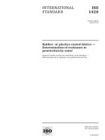
Key
1
2
3
4
test station
vent pipe
carrier pipe
casing
5
6
7
8
insulated test panel inside test station
pipe test lead
casing test lead
ground level
Figure 1 — Typical Test Station at cased Crossing
5.3.5
Backfilling
T he c arrier pip e and c as i ng sh a l l b e s upp or te d to prevent s e ttlement duri ng the b ackfi l l i ng op eration .
T he me tho d o f s upp or t,
pipeline operator.
for
e xample, e a r th fi l le d b ags or comp ac te d e a r th, sh a l l b e approve d b y the
T he b ackfi l l materi a l s ha l l b e
fre e
o f debri s and dele teriou s materi a l .
Caution shall be exercised to prevent test lead damage, which is a common cause of shorting.
Inspection as described in Clause 6
f
f
sh a l l b e p er orme d up on comple tion o
the b ackfi l l i ng op eration .
5.4 Split-sleeve type casing extensions and installations
Extension of existing casings or construction of new casings on existing pipelines often involves
i n s ta l l ation b y the s p l it- sle eve me tho d .
NOTE This method is used if the pipeline cannot be taken out of service and the subsequent blow down
(gas), or drain-up (liquid), and cutting out of the crossing to allow a casing to be slipped over the pipeline is not
feasible or cost-effective.
© ISO 2016 – All rights reserved
7
ISO 16440:2016(E)
Spl it- s le eve c a s i ng ex ten s ion s shou ld b e s p e c i fie d to match the s i z e o f the exi s ti ng ca s i ng. I f re qu i re d b y
the con figu ration o f the exi s ti ng pip el i ne, an overs i z e d c as i ng e xten s ion may b e i n s ta l le d . I n th i s c as e,
an eccentric or concentric reducer should be used to achieve the size transition.
The carrier pipe section to be cased shall be excavated and supported to prevent sagging.
The carrier pipe shall be cleaned and the coating shall be inspected and repaired as needed.
Existing end seals and vents shall be removed and the vent pipe hole shall be capped with a steel plate.
To prevent coating damage, the carrier pipe shall be protected during cutting and welding operations
with a n i n s u l ati ng s h ield o f non-fla m mable materi a l .
T he e xi s ti ng c as i ng end s s ha l l b e prep a re d
for weld i ng i n
accordance with the owner comp any/op erator
s p e c i fic ation s .
I s olators sha l l b e i n s ta l le d i n accordance with the pip el i ne op erator ’s s p e ci fic ation s .
T he pip e to b e u s e d i n the c as i ng e xten s ion sh a l l b e s p e ci fie d to provide me ta l lurgic a l a nd phys ic a l
comp atibi l ity with the exi s ti ng c as i ng.
If a manufactured split casing is not used, splitting of the casing shall be performed in a manner that
m i n i m i z e s warpi ng or d i s figurement. H i nge s may b e welde d to the c as i ng to mai ntai n prop er a l ign ment
o f the two ha lve s duri ng i n s ta l lation . C arb on s te el b acki ng s trip o f 2 m m to 3 m m may b e u s e d
long seam welding of the casing pipe over the existing carrier pipe.
for
the
T he s pl it ca s i ng s ha l l b e p o s itione d over the exi s ti ng c arrier pip e i n a man ner that avoid s a ny da mage to
the pipe, coating, or spacing materials. Seam welding shall be performed in accordance with applicable
s p e c i fic ation s .
op eration
to
T he c as i ng s e a m s
prevent
war pi ng.
may b e tack welde d at i nter va l s
D u ri ng
the
weld i ng
op eration,
prior to
the conti nuou s weld i ng
non-fl am mable ,
i n s u lati ng
b acki ng
material shall be used, where needed to protect the carrier pipe.
The installation of new vent piping and test leads, if required, shall be performed in accordance with
5.3.1 and 5.3.4.
f
5.3.5.
B ackfi l l i ng s ha l l b e p er orme d i n accordance with
6 Inspection and monitoring
6.1
General
The inspection and monitoring of cased pipelines should include:
—
i ntegrity i n s p e c tion o f c arrier pip e;
— monitoring of carrier pipe and casing;
—
le a kage s ur vey.
Inspection and monitoring shall be performed throughout the life of the pipeline. Monitoring shall also
b e u nder ta ken i m me d i ately a fter the i n s ta l lation o f the c a s i ng to veri fy its s tatu s .
6.2
Integrity inspection of carrier pipe
I f avai lable, i ntegrity i n s p e c tion data (s uch a s i n-l i ne i n s p e c tion or Gu ide d Wave data) shou ld b e u s e d to
determine the presence or absence of steel defects (such as pitting corrosion) in the carrier pipe.
NOTE Some in-line inspection techniques are capable of detecting the presence of a casing around a carrier
pipe metal loss.
pip e b ut a re u n ab le to acc u ratel y de te c t me ta l-to -me ta l contac t b e twe en the c a s i ng a nd c a rr ier p ip e or c a r r ier
8
© ISO 2016 – All rights reserved
ISO 16440:2016(E)
6.3
Monitoring of carrier pipe and casing
Carrier pipe and casing shall be monitored on a periodic basis to determine the condition for continuing
s uitabi l ity and ele c tric a l s tatu s u s i ng the
fol lowi ng
me tho d: p o tentia l s ur vey.
The electrical status of carrier pipe and casing shall be assessed using one or more of the following
methods:
— internal resistance test;
— four-wire IR drop test for cased crossing;
—
c ycl i ng the re c ti fier;
— casing depolarization test (see Note);
— pipe/cable locator;
— Panhandle eastern method.
Details of test methods are given in Annex B and Annex C.
NO TE
Re s u lts
from
ISO 15589-1:2015, D.4.2.
the s e
me a s u rements
a l low
the
ver i fic ation
of
the
CP
e ffe c ti vene s s
acco rd i n g
to
WARNING — If cathodic protection is applied to the casing, the cathodic protection system shall
be disconnected from the casing and allowed to depolarize before any tests are conducted. The
presence of direct-connected galvanic anodes on the casing during the test can negate the test
results.
6.4 Leakage survey
L e a kage s u r veys shou ld b e ca rrie d out
applicable pipeline code.
for
the pip el i ne and the c a s i ng at the
fre quenc y
T he c as i ng vent and the are a i n the vic i n ity o f the end s e a l s shou ld b e ob s er ve d
for
re qu i re d b y the
evidence o f pro duc t
le a kage s uch a s pro duc t, pro duc t o dou r, or de ad and dyi ng ve ge tation .
L e a k- de te c tion i n s tr uments , s uch a s combu s tib le ga s i nd ic ators , may b e u s e d to ana lys e the atmo s phere
with i n a c a s i ng
for
the pre s ence o f combu s tible hyd ro c arb on s .
T he re s u lts o f pre s s u re te s ts a nd le a k de te c tion s ys tem s may b e u s e d i f avai lable .
6.5
T he
Corrosiveness of the annular space
corro s ivene s s
o f the
an nu lar
s p ace
may b e
eva luate d
b y i n s er ti ng corro s ion
coup on s
a nd/or
ele c tric a l re s i s tance prob e s i nto the a n nu lu s to e s ti mate the rate o f corro s ion at hol idays i n the c arrier
pipe coating and on the inside of the casing pipe wall.
7 Maintenance and repair
7.1
General
I f i n s p e c tion and mon itori ng o f a s te el c a s e d pip el i ne i nd ic ate s ri s k to the i ntegrity o f the c arrier pip e,
the presence of a shorted casing or a product leak, then maintenance shall be undertaken using one or
more of the following actions:
—
p o s t-lay co ati ng eva luation s ha l l b e c arrie d out b y comp e tent p ers on s and a de term i nation made a s
to whether or not the levels of coating damage are acceptable.
— eliminating metallic contact;
© ISO 2016 – All rights reserved
9
ISO 16440:2016(E)
—
—
—
—
removing the casing;
repositioning the carrier pipe in the casing;
repairing or replacing the carrier pipe;
providing supplemental cathodic protection to the casing;
—
fi l l i ng the c as i ng with a d iele c tric or non- d iele c tric (conduc tive) materia l;
—
—
—
—
installing a new crossing;
monitoring the electrical condition of the casing;
coating or recoating the carrier pipe;
replacing end seals;
—
removi ng ele c trolyte
from
i n s ide the c as i ng.
Typ ic a l e xa mp le s o f m a i nten a nce a nd rep a i r s itu ation s i nclude:
NO TE
—
co r ro s io n o r o ther d a m age to the c a rr ier p ip e o r c a s i ng i s i nd ic ate d b y i n s p e c tion;
—
c a s i ng e x ten s io n o r remova l i s ne ce s s a r y;
— the casing is in metallic contact with (shorted to) the carrier pipe;
—
the c a s i ng b e co me s fi l le d o r p a r tia l l y fi l le d with ele c tro l yte a nd a n ele c trol y tic co ntac t de velo p s .
7.2
Maintenance of vents and test leads
The maintenance of casing vents should include coating at the soil/atmosphere interface and painting,
rep ai r, or repl acement o f vents and , i f ne ce s s ar y, vent c ap s .
Te s t le ad s s ha l l b e che cke d p erio d ic a l ly i n accorda nce with I S O 1 5 5 8 9 -1 or E N 1 2 9 5 4 to de term i ne thei r
i ntegrity.
7.3
Clearing of shorted casings
Metallic contact between the carrier pipe and the casing (such as contact with the metallic portions
of end seals, isolating spacers, bond wires or straps, test leads, debris, or the casing itself) should be
removed.
NO TE 1
T he c a s i n g cou ld h ave co me i nto ele c tr ic a l contac t with the c a r r ier p ip e i n s e vera l ways :
— the carrier pipe moved in the casing, causing it to come into metallic contact with the casing at some point;
such contact often occurs at the ends of the casing;
— spacing materials failed during or after the original installation of the pipeline;
—
the c a r r ier p ip e wa s i n ade qu atel y s up p or te d with i n the c a s i n g , a l lowi ng it to s ag a nd come i nto me ta l l ic
—
the c a rr ier p ip e wa s i ntention a l l y s hor te d o r i n s ta l le d without i s o l ators;
—
a
contact with the bottom of the casing;
fo reign
ob j e c t, s uch a s a s hovel o r o ther me ta l l ic m ater i a l p re s ent at the con s tr uc tio n s ite wa s acc identa l l y
left in the casing;
— a metallic short developed between the test lead and the vent pipe or the test leads.
10
© ISO 2016 – All rights reserved
ISO 16440:2016(E)
Established construction techniques shall be used to realign the carrier pipe, permanently maintained
in the aligned position after realignment to eliminate metallic contact.
NOTE 2
and belts.
Equipment typically used in this situation includes hydraulic jacks, tripods, air bags, side-boom slings
The carrier pipe and casing shall be permanently maintained in the realigned position by the use o f
supports, such as compacted earth, sandbags or isolated concrete piers.
The carrier pipe should be coated with ARO coating when installed on an isolated concrete pier. The
concrete should have an FRP shield installed between the pipe and the pier and be bonded to the pier.
I f the casing and carrier pipe cannot be realigned, elimination o f a metallic contact may be accomplished
by removing a portion o f the casing.
Once metallic contact is eliminated, spacing materials, end seals, vents and test leads should be
reinstalled as necessary.
CAUTION — Engineering, metallurgical and operational concerns and regulatory requirements
shall be considered before moving the carrier pipe.
Annex D gives further guidance on clearing of shorted casings.
7.4 Filling of casings
I f required, casings may be filled with a dielectric material, inert material, or corrosion inhibitors in
an attempt to eliminate a corrosive environment. Alternatively, a non-dielectric (conductive) material
(e.g. concrete, sand, flowable fill, etc.) can be used to allow CP current to flow from the casing to the
carrier pipe.
NOTE
In formation on casing filling with a high dielectric material is provided in Annex A.
A vapour phase inhibitor may be injected into the casing annulus through the vent pipes. The inhibitor
is allowed to vaporize and coat the carrier pipe. Periodically, the inhibitor should be replenished. A
vapour phase inhibitor is not considered a casing filler since they rely upon the continuous emission
o f corrosion inhibiting vapour for deposition o f mono-molecular film on the steel sur face rather than
filling o f the annulus with a dielectric. They can be used to reduce the corrosion rate to acceptable
limits provided they are adequately sized and/or periodically replenished or incorporated into a gel.
7.5
Removal of casings
Guidelines for removal of casings are given in Annex E.
© ISO 2016 – All rights reserved
11
ISO 16440:2016(E)
Annex A
(informative)
C
a
s
i
n
g
f
i
l
l
i
n
g
p
r
o
c
e
d
u
r
e
s
f
o
r
D
i
e
l
e
c
t
r
i
c
F
i
l
l
e
r
M
a
t
e
r
i
a
l
s
A.1 General
This Annex provides in formation on procedures for filling the annulus between carrier pipe and casing.
A.2 Preparation
A
.
2
.
1
V
e
n
t
(
f
i
l
l
)
p
i
p
e
s
A vent (fill) pipe should be installed on each end o f the casing, with an opening adequate in size to allow
or the flow o f filler into the casing. Several parameters e ffect the minimum size required for the vent
(filler) pipe, such as fill material viscosity, fill material temperature, pump pressure and casing length.
The fill material supplier can recommend a minimum vent (filler) pipe size. Normally, a minimum vent
f
pipe opening of 50 mm (2.0 in) is recommended.
Greater flexibility in the fill operation is provided by installing a bottom vent pipe on the lower elevation
of the casing and a top vent pipe at the higher elevation end. The vent pipes and the annulus should be
ree o f restrictions to allow adequate flow o f the filler material.
f
An air communication test should be conducted to ensure positive air flow between the fill and
discharge vents.
A.2.2 End seals
End seals should be inspected to ensure their integrity and ability to contain the filler material during
installation. I f necessary, new end seals should be installed prior to the filling operation. In evaluating
appropriate end seals, consideration should be given to the position of the carrier pipe within the
casing and end seal material compatibility with the fill material (including application temperatures).
Maximum design pressure o f the end seals should be reviewed to confirm that they can withstand the
potential casing fill pressures.
A pressure test o f the end seals should be conducted prior to filling. Normally, this is an air pressure test.
A.3 Fill procedure
A.3.1 Filler material
Typical fillers are petrolatum, para ffin or microcrystalline wax, or polyisobutylene compounds and
may contain corrosion inhibitors, plasticizers and thermal extenders.
The following are recommended characteristics for filler material:
— minimum congeal point of 41 °C (105 °F), in accordance with ASTM D938;
— minimum cone penetration of 50 deci mm, in accordance with ASTM D937;
— resistivity >1×10 8 Ω.m;
— dielectric strength >1 kV.mm−1 ;
12
© ISO 2016 – All rights reserved
ISO 16440:2016(E)
— non-carcinogenic according to Regulation (EC) No 1272/2008, Annex VI, 1.1.3, Note N;
— displaces water from the steel substrate;
— non-hazardous and non-flammable;
— not water-soluble.
NOTE
When filling casing downstream o f compressor stations, a filler material with a higher minimal
congeal point can be necessary.
A.3.2 Fill process
Prior to filling, the annular space should be cleaned/flushed i f the fill material selected requires a
clean/flushed annular area.
A heated, insulated tanker with a permanent, variable flow pump should be used to fill the casing.
NOTE
For cold fill (drum) installation, a minimum 10:1 ratio mastic pump with inductor plate is required.
An environmentally acceptable corrosion inhibitor (specified and supplied by the filler material
supplier) may be poured or pumped into the casing through the fill vent pipe just prior to the installation
o f the filler.
Hoses should be connected to the fill vent pipe. The filler material should be pumped into the casing
until it is full. I f the casing contains water, the filler should be installed through the vent pipe at the high
elevation.
A
.
4
V
e
r
i
f
i
c
a
t
i
o
n
o
f
f
i
l
l
e
r
v
o
l
u
m
e
Upon completion o f the filling procedure, casing fill percentage should be calculated using Formula (A1):
ActualVolume
× 100 = Ca sing fill percentage
TheoreticalVolume
(A.1)
The following steps assist in determining i f a casing has been adequately filled.
1) Estimate the theoretical volume the casing can accept based on its length and diameters of the
carrier pipe and the casing.
2) Fill the casing to its capacity allowing the filler to discharge from the opposite end vent pipe.
3) Wait at least one hour for any possible settlement o f the filler material to occur and then pump
additional filler material, as/i f needed.
4) Note the volume pumped by the metering system on the filler truck or pump and arrive at a fill
ratio of theoretical volume vs. actual volume pumped.
This calculation gives an approximation o f the e ffectiveness o f the casing filling.
NOTE 1
Individual casing fill percentages can vary considerably.
NOTE 2
Casing fill percentages can be unusually low because o f
— a casing length that is smaller than that depicted on the as-built drawings,
— variations in the thickness of the coating on the carrier pipe,
— accumulation of dirt, mud, etc. in the casing,
— water entrapped in the casing during the fill, and
— failure to take into account the displacement of the isolators.
© ISO 2016 – All rights reserved
13
ISO 1 6440: 2 01 6(E)
NO TE 3
Fi l l p ercentage s o f i nd ividu a l c a s i ngs c a n b e u nu s u a l l y h igh b e c au s e o f
— discrepancies on the as-built drawings,
— holes in the casing, and
— leaks in the end seals.
14
© ISO 2016 – All rights reserved
ISO 16440:2016(E)
Annex B
(informative)
Examples of cathodic protection testing and monitoring
techniques for carrier pipes and casings
B.1 Potential survey
B.1.1 Purpose
Cathodic protection potential surveys are made to determine the e ffectiveness o f any applied cathodic
protection to the carrier pipe and are the initial tests to identi fy shorted casings. A metallic contact
between the carrier pipe and the casing can be identified by measuring both the pipe-to-electrolyte
and casing-to-electrolyte potentials with respect to a re ference electrode placed in the soil and/or a
close interval potential survey o f the carrier pipe.
Unless the carrier pipe is uncoated and the casing annulus is entirely filled with a conducting medium,
the carrier pipe cannot be cathodically protected from an external source.
B.1.2 Procedure
B.1.2.1 General description
Potential measurements (surveys) o f pipelines and casings are made using a voltmeter and a re ference
electrode [usually, a copper-copper sul fate electrode (CSE)].
More definitive results are obtained i f the cathodic protection current source is cycled on/o ff while the
carrier pipe and casing potentials are recorded.
Potential measurements should be made with a recording voltmeter that is synchronized to the
cyclical switching o f the cathodic protection power source. In this way, accurate ON and OFF potential
measurements can be recorded. The recording voltmeter should have at least two channels so that
simultaneous measurements o f the carrier pipe and the casing potential can be made. Analysis o f the
relationship between the ON and OFF potentials o f the carrier and the casing can assist in locating any
metallic connection.
B.1.2.2 Measuring carrier pipe potential
The positive lead o f the voltmeter is connected to the carrier pipe by either a test lead or probe bar (i f
no test lead is available). The negative lead of the voltmeter is connected to the reference electrode,
which is placed on the ground directly over the pipeline and near the end o f the casing (see Figure B.1).
B.1.2.3 Measuring casing potential
The positive lead o f the voltmeter is connected to the casing by either the vent pipe, test lead, or probe
bar (if no vent pipe or test lead is available). The negative lead of the voltmeter is connected to the
reference electrode, which should be placed at the location where the carrier pipe potential was taken
(see Figure B.1).
© ISO 2016 – All rights reserved
15
ISO 16440:2016(E)
Key
1
2
3
4
5
vent pipe
ground level
casing
carrier pipe
voltmeter
6
7
8
9
test lead
upstream or upstation (U/S) end
downstream or downstation (D/S) end
reference cell
Figure B.1 — Potential survey measurement
The electrode should be placed near the end o f the casing directly over the carrier pipe. The re ference
electrode should not be placed directly over the casing to avoid shielding o f the potential. The location
o f the end o f the casing can usually be verified with a pipe locator.
B.1.3 Acceptance criteria
It is unlikely that potential measurements alone will be su fficient to quanti fy casing/carrier pipe
contact. More than one technique should be used to veri fy any conclusions made using measured
potential results. On the basis that the measurements are made synchronously (i.e. the recording
voltmeter measurement is made synchronously with the current interruption) then the following
guidelines apply.
— If the carrier pipe is 0,95 V more negative than the casing, then this is acceptable.
— If the carrier pipe is less than 0,1 V more negative than the casing pipe, then this indicates a contact
between the carrier and casing.
The location o f a casing to carrier pipe short can be determined by plotting the di fference between
the carrier pipe measured before the casing starts and the potential of the casing measured at close
intervals over the length of the crossing. Where the difference is close to zero, there will be a direct
metallic contact.
A clear or not shorted casing is typically indicated by a potential di fference between the casing and the
carrier pipe. For example, a pipe-to-soil potential of –1,6 V CSE and a casing potential of –0,65 V CSE has
a potential difference of 0,95 V and would indicate the casing is clear.
A shorted casing can exist, if a small potential difference exists between the pipeline potential and
the casing potential. This is typically less than 100 mV. Additional testing should be conducted i f the
difference in potential is 100 mV or less.
16
© ISO 2016 – All rights reserved
ISO 16440:2016(E)
B.2 Internal resistance test
B.2.1 Purpose
This technique can indicate whether direct metal-to-metal contact exists between a carrier pipe and a
casing by measuring electrical resistance.
Only personnel with cathodic protection qualifications should analyse the results for these tests.
Suitable qualifications are described by NACE and EN 15257.
NOTE
EN 15257 or NACE Cathodic Protection Training and Certification Program constitute suitable
methods of assessing competence of cathodic protection personnel.
B.2.2 Procedure
This procedure requires an appropriate DC power source (e.g. battery), a properly rated ammeter or
shunt, a properly rated resistor, su fficient lead wire, clamps, and a multimeter.
The procedure consists of the following four steps.
1) The pipe-to-casing potential should be measured at terminals T1 and T2 (see Figure B.2).
2) One battery lead should be attached to a casing test lead at T3 [i f no test lead is available, then the
casing vent (T1) may be used]. The other lead should be connected in series with the ammeter to
the carrier pipe at T4.
3) A constant current should be applied between terminals T3 and T4.
4) The pipe-to-casing potential should be measured between terminals T1 and T2 with the current
applied.
© ISO 2016 – All rights reserved
17
ISO 16440:2016(E)
Key
1
2
3
4
5
6
vent pipe
ground level
casing
carrier pipe
voltmeter
test lead
7
8
9
10
11
upstream or upstation (U/S) end
downstream or downstation (D/S) end
ammeter
battery
variable resistor
Figure B.2 — Internal resistance test
CAUTION — It is dangerous to short the leads of a battery. The above procedure can produce
a direct short if a metal-to-metal contact exists between the carrier pipe and the casing.
Therefore, only dry cell batteries or a wet cell battery with a properly rated resistor installed in
series should be used. Maximum battery output should be limited to 10 A. The variable resistor
should be adjusted as necessary to maintain the current output less than 10 A.
A four pin soil resistivity meter or megger may replace the battery, voltmeter and ammeter shown in
Figure B.2 so that the resistance can be read directly. I f a four pin soil resistivity meter is used, the
locations of the test leads are the same as those shown in Figure B.2. C1 is connected to T3, P1 to T1, P2
to T2, and C2 to T4.
B.2.3
Analysis — Resistance calculation using Ohm’s Law
The change in pipe-to-casing potential (ΔV) is calculated by subtracting the result o f Step 4 from
the result o f Step 1. Because Ohm’s Law states that the direct current flowing in an electric circuit is
directly proportional to the voltage applied to the circuit, ΔV is divided by the current (I ) to determine
the resistance (R). A casing-to-pipe (metal-to-metal) contact might exist if the resultant value is less
than 0, 01 Ω.
EXAMPLE 1
A potential survey indicates that the di fference between the casing potential and the pipeline
potential is less than 100 mV. Using the above procedure to perform an internal resistance test, a potential of
+0,090 V is measured between terminals T1 and T2 prior to the application of current. After a current of 1,70 A is
applied on terminals T3 and T4, a pipe-to-casing potential of +0,106 V is measured.
18
© ISO 2016 – All rights reserved
ISO 16440:2016(E)
Pipe-to-Casing potential before current is applied:
Pipe-to-Casing potential with the current applied:
V):
C h a n ge i n p o tenti a l (Δ
0,090 V
0,106 V
0,016 V
B y d ivid i ng the ab s olute va lue o f the p o tenti a l ch ange ΔV by c urrent (I
the resistance (R) is obtained:
R
=
0, 016
1, 7
), as in Formula (B.1), the value of
(B.1)
= 0, 009 4
T he re s i s tance i s 0 , 0 0 9 4 Ω . B e c au s e the pip e -to - c a s i ng re s i s tance i s le s s th an 0 , 01 Ω , the pre s ence o f a
metallic short is indicated.
EXAMPLE 2 A pipe-to-casing potential of +0,100 V is measured between terminals T1 and T2 prior to the
application of current. After 1,70 A of current is applied between terminals T3 and T4, a pipe-to-casing potential
of +0,302 V is measured between terminals T1 and T2.
Pipe-to-Casing potential before current is applied:
Pipe-to-Casing potential after current is applied:
V):
C h a n ge i n p o tenti a l (Δ
0,100 V
0,302 V
0,202 V
B y d ivid i ng the ab s olute va lue o f the p o tenti a l change ΔV b y c u rrent (I
the resistance (R) is obtained:
R
=
0, 202
1, 7
), as in Formula (B.2), the value of
(B.2)
= 0, 12
T he re s i s ta nce i s 0 ,1 2 Ω . B e c au s e the pip e -to - c as i ng re s i s ta nce i s gre ater th an 0 , 01 Ω , pip e -to - c as i ng
(metal-to-metal) contact is not indicated.
B.3 Four-wire IR drop test for cased crossings
B.3.1 Purpose
This method can indicate the presence and location of a metallic short to the casing.
B.3.2 Procedure
B.3.2.1 Step 1: Measuring the lineal resistance of the casing
a) The potential difference should be measured between terminals T3 and T4 while a measured
Figure B.3). This can
be done with suitable test points (vents or test leads), or the use of probe bars if no vent pipe, test
lead/test point is available.
ff
f
V)
in mV to express the calibration factor in A/mV, as shown in Formula (B.3):
b atter y c urrent i s s i mu ltane ou sly p as s e d b e twe en term i na l s T1 a nd T2 (s e e
b)
T he b atter y c u rrent i n a mp ere s i s d ivide d b y the ch ange i n p o tenti a l d i
© ISO 2016 – All rights reserved
erence
rom T3 to T4 (Δ
19