Tiêu chuẩn iso 16254 2016
Bạn đang xem bản rút gọn của tài liệu. Xem và tải ngay bản đầy đủ của tài liệu tại đây (1.05 MB, 48 trang )
INTERNATIONAL
STANDARD
ISO
16254
First edition
2016-05-01
Acoustics — Measurement of sound
emitted by road vehicles of category
M and N at standstill and low speed
operation — Engineering method
Acoustique — Mesurage du bruit émis par les véhicules routiers de
catégories M et N à l’arrêt et en fonctionnement à basse vitesse —
Méthode d’expertise
Reference number
ISO 16254:2016(E)
I n tern ati o n al Org an i z ati o n fo r S tan d ard i z ati o n
© ISO 2016
ISO 16254:2016(E)
COPYRIGHT PROTECTED DOCUMENT
© ISO 2016, Published in Switzerland
All rights reserved. Unless otherwise specified, no part o f this publication may be reproduced or utilized otherwise in any form
or by any means, electronic or mechanical, including photocopying, or posting on the internet or an intranet, without prior
written permission. Permission can be requested from either ISO at the address below or ISO’s member body in the country o f
the requester.
ISO copyright o ffice
Ch. de Blandonnet 8 • CP 401
CH-1214 Vernier, Geneva, Switzerland
Tel. +41 22 749 01 11
Fax +41 22 749 09 47
www.iso.org
ii
I n tern ati o n al Org an i z ati o n fo r S tan d ard i z ati o n
© ISO 2016 – All rights reserved
ISO 16254:2016(E)
Contents
Page
Foreword .......................................................................................................................................................................................................................................... v
Introduction ................................................................................................................................................................................................................................ vi
1
Scope ................................................................................................................................................................................................................................. 1
2
Normative references ...................................................................................................................................................................................... 1
3
Terms and definitions ..................................................................................................................................................................................... 2
4
Symbols and abbreviated terms ........................................................................................................................................................... 3
5
Instrumentation .................................................................................................................................................................................................... 4
5.1 Instruments for acoustic measurement ............................................................................................................................ 4
5.1.1 General...................................................................................................................................................................................... 4
5.1.2 Calibration ............................................................................................................................................................................. 5
5.1.3 Compliance with requirements ........................................................................................................................... 5
5.2 Instrumentation for speed measurements ..................................................................................................................... 5
5.3 Meteorological instrumentation .............................................................................................................................................. 5
6
Acoustic environment, meteorological conditions, and background noise ............................................ 6
6.1 Test site .......................................................................................................................................................................................................... 6
6.1.1 General...................................................................................................................................................................................... 6
6.1.2 Outdoor testing ................................................................................................................................................................. 6
6.1.3 Indoor hemi anechoic or anechoic testing ................................................................................................ 7
.............................................................................. 9
6.2 Meteorological conditions ............................................................................................................................................................. 9
6.2.1 General...................................................................................................................................................................................... 9
6.2.2 Outdoor measurements ............................................................................................................................................. 9
6.2.3 Indoor measurements ................................................................................................................................................. 9
6.3 Background noise ................................................................................................................................................................................. 9
6.3.1 Measurement criteria for A-weighted sound pressure level ..................................................... 9
6.3.2 Vehicle A-weighted sound pressure level measurement correction criteria ............ 10
......... 11
6.3.4 Measurement background noise when testing a component ................................................ 12
7
Test procedures .................................................................................................................................................................................................. 12
7.1 Full vehicle testing ............................................................................................................................................................................ 12
7.1.1 Microphone positions ............................................................................................................................................... 12
7.1.2 Conditions of the vehicle ........................................................................................................................................ 12
7.1.3 Test mass of vehicle .................................................................................................................................................... 13
.............................................................................................................................. 13
7.1.5 Operating conditions ................................................................................................................................................. 13
7.1.6 Measurement readings and reported values ........................................................................................ 15
7.1.7 Data compilation ........................................................................................................................................................... 16
7.1.8 Standstill results ............................................................................................................................................................ 16
7.1.9 Slow speed cruise result at 10 km/h ........................................................................................................... 16
7.1.10 Reported value ................................................................................................................................................................ 16
f
f
f ........................................................................................ 16
7.2.1 General................................................................................................................................................................................... 16
7.2.2 Instrumentation ............................................................................................................................................................ 17
7.2.3 Signal processing requirements ...................................................................................................................... 17
7.2.4 Test facilities ..................................................................................................................................................................... 17
f
.................................................................................... 17
.......................................................................................................................................................... 20
8
Test report................................................................................................................................................................................................................ 21
Annex A (informative) Information on development of ISO 16254 .................................................................................. 22
Annex B (informative) Development of frequency shift information ............................................................................. 24
7.2
6.1 .4
I ndo o r external s o und generatio n sys tem tes ting
6.3 .3
B ackgro und no is e requirements when analys ing in o ne- third- o ctave b ands
7.1 .4
Tyre s electio n and co nditio n
M eas urement o
7.2 .5
7.3
requency s hi t
Frequency s hi t meas urement tes t p ro cedure
M eas urement uncertainty
© ISO 2016 – All rights reserved
I n tern ati o n al Org an i z ati o n fo r S tan d ard i z ati o n
s o und to determine
iii
ISO 16254:2016(E)
Annex C (informative) Relevance of objective acoustic data to pedestrian safety............................................. 26
Annex D (informative) Measurement uncertainty — Framework for analysis according to
ISO/IEC Guide 98-3 (GUM) ....................................................................................................................................................................... 28
Annex E (normative) Testing requirements for reduced uncertainty ............................................................................ 34
Annex F (informative)
f
f
f
..... 35
Annex G (informative) Flowchart of the procedure for measurement and reporting of
background noise ............................................................................................................................................................................................. 37
Annex H (informative) Flowchart for the procedure to correct A-weighted sound pressure levels38
Annex I (informative) Flowchart for the procedure to report A-weighted one-third-octaveband sound pressure levels .................................................................................................................................................................... 39
Bibliography ............................................................................................................................................................................................................................. 40
iv
I n tern ati o n al Org an i z ati o n fo r S tan d ard i z ati o n
F
r
e
q
u
e
n
c
y
i
d
e
n
t
i
f
i
c
a
t
i
o
n
o
t
o
n
e
s
u
s
i
n
g
t
h
e
a
s
t
F
o
u
r
i
e
r
t
r
a
n
s
o
r
m
a
t
i
o
n
© ISO 2016 – All rights reserved
ISO 16254:2016(E)
Foreword
ISO (the International Organization for Standardization) is a worldwide federation of national standards
bodies (ISO member bodies). The work o f preparing International Standards is normally carried out
through ISO technical committees. Each member body interested in a subject for which a technical
committee has been established has the right to be represented on that committee. International
organizations, governmental and non-governmental, in liaison with ISO, also take part in the work.
ISO collaborates closely with the International Electrotechnical Commission (IEC) on all matters o f
electrotechnical standardization.
The procedures used to develop this document and those intended for its further maintenance are
described in the ISO/IEC Directives, Part 1. In particular the different approval criteria needed for the
di fferent types o f ISO documents should be noted. This document was dra fted in accordance with the
editorial rules of the ISO/IEC Directives, Part 2 (see www.iso.org/directives).
Attention is drawn to the possibility that some o f the elements o f this document may be the subject o f
patent rights. ISO shall not be held responsible for identi fying any or all such patent rights. Details o f
any patent rights identified during the development o f the document will be in the Introduction and/or
on the ISO list of patent declarations received (see www.iso.org/patents).
Any trade name used in this document is in formation given for the convenience o f users and does not
constitute an endorsement.
For an explanation on the meaning o f ISO specific terms and expressions related to con formity
assessment, as well as information about ISO’s adherence to the WTO principles in the Technical
Barriers to Trade (TBT) see the following URL: Foreword - Supplementary in formation
The committee responsible for this document is ISO/TC 43, Acoustics, Subcommittee SC 1, Noise, in
collaboration with ISO/TC 22, Road vehicles.
© ISO 2016 – All rights reserved
I n tern ati o n al Org an i z ati o n fo r S tan d ard i z ati o n
v
ISO 16254:2016(E)
Introduction
The advent o f road transport vehicles that rely, in whole or in part, on alternative drive trains (e.g.
electromotive propulsion) are serving to reduce both air and noise pollution and their adverse impacts
on citizens throughout the world. However, the environmental benefits achieved to date by these
“hybrid or pure electric” road vehicles have resulted in the unintended consequence o f removing a
source o f audible signal that is used by various groups o f pedestrians (e.g. in particular, blind and low
vision persons) to detect the approach, presence and/or departure of road vehicles.
Therefore, this International Standard has been developed to provide a method to measure the sound
emission o f road vehicles in standstill and low speed operation, as well as to quanti fy the characteristics
o f any external sound-generation system installed for the purpose o f conveying acoustic in formation
about the approach, presence and/or departure o f the vehicle to nearby pedestrians.
This International Standard was developed in cooperation with the Society o f Automotive Engineers
(SAE) Vehicle Sound for Pedestrians Subcommittee.
vi
I n tern ati o n al Org an i z ati o n fo r S tan d ard i z ati o n
© ISO 2016 – All rights reserved
INTERNATIONAL STANDARD
ISO 16254:2016(E)
Acoustics — Measurement of sound emitted by road
vehicles of category M and N at standstill and low speed
operation — Engineering method
1 Scope
This International Standard is derived from ISO 362-1 and specifies an engineering method for
measuring the sound emitted by M and N category road vehicles at standstill and low speed operating
conditions. The specifications reproduce the level o f sound which is generated by the principal vehicle
sound sources consistent with stationary and low speed vehicle operating conditions relevant for
pedestrian sa fety. The method is designed to meet the requirements o f simplicity as far as they are
consistent with reproducibility o f results under the operating conditions o f the vehicle.
The test method requires an acoustic environment which is only obtained in an extensive open space.
Such conditions usually exist during the following:
— measurements o f vehicles for regulatory certification;
— measurements at the manu facturing stage;
— measurements at o fficial testing stations.
The results obtained by this method give an objective measure o f the sound emitted under the specified
conditions o f test. It is necessary to consider the fact that the subjective appraisal o f the annoyance,
perceptibility, and/or detectability o f di fferent motor vehicles or classes o f motor vehicles due to their
sound emission are not simply related to the indications o f a sound measurement system. As annoyance,
perceptibility and/or detectability are strongly related to personal human perception, physiological
human condition, culture, and environmental conditions, there are large variations and therefore these
terms are not use ful as parameters to describe a specific vehicle condition.
Spot checks o f vehicles chosen at random rarely occur in an ideal acoustic environment. I f measurements
are carried out on the road in an acoustic environment which does not fulfil the requirements stated in
this International Standard, the results obtained might deviate appreciably from the results obtained
using the specified conditions.
In addition, this International Standard provides an engineering method to measure the performance
o f external sound generation systems intended for the purpose o f providing acoustic in formation to
pedestrians on a vehicle’s operating condition. This in formation is reported as objective criteria related
to the external sound generation system’s sound pressure level, frequency content, and changes in
sound pressure level and frequency content as a function o f vehicle speed. As such, these measures can
provide pedestrians with information on the location, speed, acceleration, and deceleration behaviour
of a vehicle. Annex A contains background information relevant in the development of this International
Standard.
2 Normative references
The following documents, in whole or in part, are normatively re ferenced in this document and are
indispensable for its application. For dated re ferences, only the edition cited applies. For undated
re ferences, the latest edition o f the re ferenced document (including any amendments) applies.
ISO 362–1,
Measurement of noise emitted by accelerating road vehicles — Engineering method — Part 1: M
and N categories
© ISO 2016 – All rights reserved
I n tern ati o n al Org an i z ati o n fo r S tan d ard i z ati o n
1
ISO 16254:2016(E)
ISO 10844, Acoustics — Specification of test tracks for measuring noise emitted by road vehicles and
their tyres
ISO 26101, Acoustics — Test methods for the qualification of free-field environments
IEC 60942, Electroacoustics — Sound calibrators
IEC 61260–1, Electroacoustics — Octave-band and fractional-octave-band filters — Part 1: Specifications
IEC 61672–1, Electroacoustics — Sound level meters — Part 1: Specifications
SAE J2889–1, Measurement of Minimum Noise Emitted by Road Vehicles
ISO/IEC Guide 98–3, Uncertainty of measurement — Part 3: Guide to the expression of uncertainty in
measurement (GUM:1995)
3 Terms and definitions
For the purposes o f this document, the terms and definitions given in ISO 362–1 and SAE J2889–1 and
the following apply.
3.1
front reference plane
vertical plane tangent to the leading edge of the vehicle
3.2
rear reference plane
vertical plane tangent to the trailing edge of the vehicle
3.3
external sound generation system
system that provides an acoustic signal to the external environment o f the vehicle for the purpose to
provide information to pedestrians
3.4
component
external sound generation system
separately from the vehicle
(3.3) intended to emit sound information which can be tested
3.5
kerb mass
complete shipping mass o f a vehicle fitted with all equipment necessary for normal operation plus the
mass of the following elements for M1, N1 and M2 having a maximum authorized mass not exceeding
3 500 kg:
— lubricants, coolant (i f needed), washer fluid;
— fuel (tank filled to at least 90 % o f the capacity specified by the manu facturer);
— other equipment i f included as basic parts for the vehicle, such as spare wheel(s), wheel chocks, fire
extinguisher(s), spare parts and tool kit
Note 1 to entry: The definition o f kerb mass can vary from country to country, but in this International Standard
it re fers to the definition contained in ISO 1176.
Note 2 to entry: M and N vehicle categories are defined in SAE J2889–1 and ISO 362-1.
3.6
mass in running order
nominal mass of an N2, N3 or M2 vehicle having a maximum authorized mass greater than 3 500 kg, or
an M3 vehicle as determined by the following conditions:
2
I n tern ati o n al Org an i z ati o n fo r S tan d ard i z ati o n
© ISO 2016 – All rights reserved
ISO 16254:2016(E)
a) the mass in running order is taken as the sum o f the unladen vehicle mass and the driver’s mass;
b) in the case o f category M2 and M3 vehicles that include seating positions for additional
crewmembers, their mass is incorporated in the same way and equal to that o f the driver
Note 1 to entry: The driver’s mass is calculated in accordance with ISO 2416.
Note 2 to entry: Unladen vehicle mass is defined in ISO 362-1.
3.7
full vehicle operation
operation o f a vehicle with all systems and components operating according to the manu facturer’s
specification for normal road use
3.8
simulated vehicle operation
operation o f a vehicle with some systems or components disabled to reduce noise inter ference during
testing which may include external signals applied to the vehicle to simulate actual in-use signals
3.9
lowest frequency of interest
requency below which there is no signal content relevant to the measurement o f sound emission for
f
the vehicle under test
4
Symbols and abbreviated terms
T
a
b
l
e
1
—
S
y
m
b
o
l
s
a
n
d
a
b
b
r
e
v
i
a
t
e
d
Symbol
Unit
Subclause
AA′
—
7.1.5.1
BB′
—
7.1.5.1
δ1 - δ7
dB
D.2
δ8 - δ14
dB
D.3
δ15 - δ21
,speed
Hz
—
Hz
D.4
6.1.3
7.2.5.2
,ref
Hz
CC′
fi
t
e
r
m
s
a
n
d
t
h
e
p
a
r
a
g
r
a
p
h
i
n
w
h
i
c
h
t
h
e
y
a
r
e
f
i
r
s
t
u
s
e
d
Explanation
Line perpendicular to vehicle travel which indicates the
beginning of the zone to record sound pressure level during test.
Line perpendicular to vehicle travel which indicates end of the
zone to record sound pressure level during test.
Input quantities to allow for any uncertainty in A-weighted
sound pressure level.
Input quantities to allow for any uncertainty in one-third-
octave-band A-weighted sound pressure level.
Input quantities to allow for any uncertainty in frequency
measurement used for the determination o f frequency shi ft.
Centreline of vehicle travel.
Single frequency component o f external sound generation
system at a given vehicle speed.
Single frequency component o f external sound generation
system at re ference vehicle speed.
Frequency shi ft expressed in percent o f a re ference frequency.
Frequency resolution o f narrowband analysis used to measure
frequency spectra for the purpose o f determining frequency
del f
%
7.2.5.2
7.2.5.2
∆f
Hz
7.2.3
s
Hz
—
5.1.1
6.3.2
vehicle
m
6.1.3
Index for single test run within stopped or slow speed cruise
test conditions
Vehicle length used for determination of minimal space
st,fwd
dB
7.1.8
condition.
fi
_
F
j
l
L
© ISO 2016 – All rights reserved
I n tern ati o n al Org an i z ati o n fo r S tan d ard i z ati o n
shift information.
Sampling frequency used by digital signal processing system
necessary to fulfil hemi-anechoic space requirements.
Vehicle A-weighted sound pressure level in stationary forward
3
ISO 16254:2016(E)
Table 1 (continued)
Symbol
Unit
Subclause
L st,rev
dB
7.1.8
L bgn
dB
dB
dB
dB
dB
7.1.9
6.3.2
6.3.2
6.3.2
6.3.1
∆ Lbgn,p-p
dB
6.3.1
Lx
dB
D.2
L x,band
dB
D.3
L x,meas
dB
D.2
∆L
dB
6.3.2
N
—
7.2.3
PP′
—
7.1.1
vAA′
km/h
5.2
Vehicle velocity when vehicle front re ference plane in forward
motion passes line AA′. See 3.1 for definition o f front
vBB′
km/h
5.2
Vehicle velocity when vehicle front re ference plane or rear o f
vehicle in forward motion passes line BB′. See 3.1 for definition
vPP′
km/h
5.2
f
km/h
km/h
7.2.5.2
7.1.5.2
L crs,10
L corr
L test, j
L testcorr, j
vref
vtest
5
Explanation
Vehicle A-weighted sound pressure level in stationary reverse
condition.
Cruise vehicle A-weighted sound pressure level at a vehicle
speed of 10 km/h.
Background noise correction.
A-weighted sound pressure level result of jth test run.
A-weighted sound pressure level result of jth test run
corrected for background noise.
Background noise A-weighted sound pressure level.
Range of maximum to minimum value of the representative
background noise A-weighted sound pressure level over a
defined time period.
A-weighted sound pressure level for any stationary or cruise
condition for use in assessment o f measurement uncertainty.
A-weighted sound pressure level per one-third-octave band
or any stationary or cruise condition for use in assessment o f
measurement uncertainty.
A-weighted sound pressure level for any stationary or cruise
condition for use in assessment o f measurement uncertainty.
A-weighted sound pressure level of jth test result minus the
A-weighted background noise level (∆ L = Ltest, j - L bgn).
f
Block size of digital sample used for discrete Fourier
trans form or autopower spectrum analysis.
Line perpendicular to vehicle travel which indicates location of
microphones.
reference plane.
of front reference plane.
Vehicle velocity when vehicle front re ference plane in
orward motion passes line PP′. See 3.1 for definition o f front
reference plane.
Re ference vehicle velocity used for calculating frequency shi ft
percentage.
Target vehicle test velocity.
Instrumentation
5.1
5.1.1
Instruments for acoustic measurement
General
The apparatus used for measuring the sound pressure level shall be a sound level meter or equivalent
measurement system meeting the requirements o f class 1 instruments (inclusive o f the recommended
windscreen, if used). These requirements are described in IEC 61672–1.
The entire measurement system shall be checked by means o f a sound calibrator that fulfils the
requirements of class 1 sound calibrators in accordance with IEC 60942.
4
I n tern ati o n al Org an i z ati o n fo r S tan d ard i z ati o n
© ISO 2016 – All rights reserved
ISO 16254:2016(E)
Measurements shall be carried out using the time weighting “F” o f the acoustic measurement
instrument and the “A” frequency weighting also described in IEC 61672–1. When using a system that
includes a periodic monitoring of the A-weighted sound pressure level, a reading should be made at a
time interval not greater than 30 ms.
When measurements are carried out for one-third octaves, the instrumentation shall meet all
requirements of IEC 61260–1, class 1.
When measurements are carried out for frequency shi ft, the digital sound recording system shall have
at least a 16 bit quantization. The sampling rate, Fs , and the dynamic range shall be appropriate to the
signal of interest.
The instruments shall be maintained and calibrated in accordance to the instructions of the instrument
manufacturer.
5.1.2
Calibration
At the beginning and at the end o f every measurement session, the entire acoustic measurement system
shall be checked by means o f a sound calibrator as described in 5.1.1 . Without any further adjustment,
the difference between the readings shall be less than or equal to 0,5 dB. If this value is exceeded, the
results o f the measurements obtained a fter the previous satis factory check shall be discarded.
5.1.3
Compliance with requirements
Compliance o f the sound calibrator with the requirements o f IEC 60942 shall be verified once a year.
Compliance o f the instrumentation system with the requirements o f IEC 61672–1 shall be verified at
least every 2 years. All compliance testing shall be conducted by a laboratory which is authorized to
perform calibrations traceable to the appropriate standards.
5.2
Instrumentation for speed measurements
The road speed o f the vehicle shall be measured with instruments meeting specification limits o f at
least ±0,5 km/h when using continuous measuring devices.
I f testing uses independent measurements o f speed, this instrumentation shall meet specification limits
of at least ±0,2 km/h.
NOTE Independent measurements of speed are when two or more separate devices will determine the vAA′,
vBB′ and vPP′ values. A continuous measuring device will determine all required speed information with one device.
5.3
Meteorological instrumentation
The meteorological instrumentation used to monitor the environmental conditions during the test
shall meet the specifications o f the following:
— ±1 °C or less for a temperature measuring device;
— ±1,0 m/s for a wind speed-measuring device;
— ±5 hPa for a barometric pressure measuring device;
— ±5 % for a relative humidity measuring device.
© ISO 2016 – All rights reserved
I n tern ati o n al Org an i z ati o n fo r S tan d ard i z ati o n
5
ISO 16254:2016(E)
6 Acoustic environment, meteorological conditions, and background noise
6.1 Test site
6.1.1
General
T he s p e c i fic ation s
for
the te s t s ite provide the ne ce s s ar y acou s tic envi ronment to c a rr y out the
fu l l
vehicle or component tests documented in this International Standard. Outdoor and indoor test
envi ron ments that me e t the s p e ci fic ation s o f th i s I nternationa l Standard provide e qu iva lent acou s tic
envi ron ments and pro duce re s u lts that a re e qua l ly va l id .
6.1.2
T he
Outdoor testing
te s t s ite
sha l l
be
s ub s ta ntia l ly
level .
T he
te s t
track con s truc tion
and
requirements of ISO 10844. Figure 1 gives information on test site dimensions.
With i n a rad iu s o f 5 0 m a rou nd the centre o f the track, the s p ace s ha l l b e
s uch as
fence s ,
fre e from
fre e
s u r face
s ha l l
me e t
the
o f large refle c ti ng obj e c ts ,
ro cks , bridge s or bu i ld i ngs . T he te s t track and the s u r face o f the s ite s ha l l b e d r y and
ab s orbi ng materia l s , s uch a s p owder y s now or lo o s e debri s .
I n the vic i n ity o f the m icrophone s , there sh a l l b e no ob s tacle that cou ld i n fluence the acou s tic field and
no person shall remain between the microphone and the noise source. The meter observer shall be
p o s itione d s o a s no t to i n fluence the me ter re ad i ng.
NO TE 1
test track.
T he
term
B u i ld i ngs outs ide the 5 0 m rad iu s m ight h ave s ign i fic a nt i n fluence i f thei r re fle c tio n
“s ub s tanti a l ly
d i s conti nu itie s
th at
level”
wou ld
is
i ntende d
render
i nva l id
to
the
convey
that
a s s u mp tion
the
te s t
the
prop agation . T h i s i s no t to l i m it slop e s on the te s t s ite ne ce s s ar y
for
s ite
s ite
s ha l l
provide d
no t
fo c u s e s
h ave
fre e -field
on the
s lop e s
or
acou s tic
water management, d ra i nage, e tc .
E ngi ne eri ng j udgement i s exp e c te d to b e appl ie d to de term i ne the e ffe c t on the s ite o f any ob s tacle . T he
te s t track its el f i s s ubj e c t to the re qu i rements s p e c i fie d .
For the purpose of this International Standard, test track constructions and surfaces according to
f
f
to 20 km/h.
either I S O 10 8 4 4: 2 01 1 or I S O 10 8 4 4: 19 9 4 wi l l a l s o provide s ati s fac tor y re s u lts
NO TE 2
6
or veh icle s p e e d s o
up
G o ver n ment re gu l atio n s c a n re qu i re s p e c i fic s u r face re qu i rements .
I n tern ati o n al Org an i z ati o n fo r S tan d ard i z ati o n
© ISO 2016 – All rights reserved
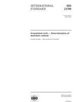
ISO 16254:2016(E)
Dimensions in metres
Key
1
area
free
o f reflecting o b j ects
microphone (height 1,2 m)
T he s h ade d a re a i s the m i n i mu m a re a to b e covere d with a s u r face comp l yi ng with I S O 10 8 4 4.
NO TE
Figure 1 — Test site dimensions
6.1.3
Indoor hemi anechoic or anechoic testing
T h i s s ub clau s e s p e ci fie s cond ition s appl ic able when te s ti ng a
fu l l
veh icle, either op erati ng as it wou ld on
the ro ad with a l l s ys tem s op erationa l or op erati ng i n a mo de where on ly the ex terna l s ou nd generation
s ys tem i s op erationa l .
T he te s t
faci l ity
sha l l me e t re qu i rements o f I S O 2 6101 with the
measurement requirements appropriate to this test method.
fol lowi ng
qua l i fic ation criteria a nd
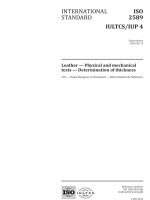
Figure 2. Points D, E, F and G are
locations used for the microphones in conducting testing according to the method described in Clause 7.
Sp ace to b e de eme d hem i-a ne choic sha l l b e defi ne d a s s hown i n
© ISO 2016 – All rights reserved
I n tern ati o n al Org an i z ati o n fo r S tan d ard i z ati o n
7
ISO 16254:2016(E)
Dimensions in metres
Key
CC’
centreline of vehicle travel
D, E, F, G microphone positions
F
i
g
u
r
e
2
—
S
p
a
t
i
a
l
d
i
m
e
n
s
i
o
n
s
f
o
r
a
c
o
u
s
t
i
c
s
p
a
c
e
d
e
f
i
n
e
d
t
o
b
e
h
e
m
i
-
a
n
e
c
h
o
i
c
For quali fying the hemi acoustic space, the following evaluation shall be conducted:
— sound source location shall be placed on the floor in middle o f the space deemed to be anechoic;
— sound source shall provide a broadband input for measurement;
— evaluation shall be conducted in one-third-octave bands;
— microphone locations for evaluation shall be on a line from the source location to each position of
microphones used for measurement in the International Standard shown by points D, E, F, and G in
Figure 2 . This is commonly referred at the microphone transverse;
— the maximum spacing of the measurement points for evaluation on the microphone transverse line
shall depend on the size o f the space deemed hemi-anechoic. A minimum o f 10 points shall be used;
— the one-third-octave bands used to establish hemi-anechoic qualification shall be defined to cover
the spectral range of interest.
The test facility shall have a cut-o ff frequency, as defined in ISO 26101, lower than the lowest frequency
of interest.
In the vicinity o f the microphones, there shall be no obstacle that could influence the acoustic field
and no person shall remain between the microphone and the noise source. The meter observer shall
be positioned so as not to influence the meter reading. Microphones shall be located as specified in
Figure 1.
NOTE
It is expected that users of this International Standard will understand that valid measurements can
only be made when the cut-o ff frequency is lower than the lowest frequency o f interest. A specific numerical
requirement for cut-o ff frequency is not given due to the range o f variation o f appropriate cut-o ff frequencies
depending upon the measured vehicle.
In the absence o f any in formation on the range o f frequencies to be measured for hemi-anechoic
qualification, it is recommended to use the frequency range from 100 Hz to 10 000 Hz.
8
I n tern ati o n al Org an i z ati o n fo r S tan d ard i z ati o n
© ISO 2016 – All rights reserved
ISO 16254:2016(E)
6.1.4 Indoor external sound generation system testing
This subclause specifies conditions applicable when testing only the external sound generation system
separate from the vehicle.
The test facility shall meet the requirements o f ISO 26101 following the same qualification criteria used
in 6.1.3 with the following exception: The space to be deemed hemi-anechoic shall extend at least 2 m in
all radial directions from the centre location used for the source.
The test facility shall have a cut-o ff frequency lower than the lowest frequency o f interest.
In the vicinity o f the microphone, there shall be no obstacle that could influence the acoustic field and
no person shall remain between the microphone and the noise source. The meter observer shall be
positioned so as not to influence the meter reading. Microphones shall be located as specified in 7.1.1.
6.2 Meteorological conditions
6.2.1
General
Meteorological conditions are specified to provide a range o f normal operating temperatures and to
prevent abnormal readings due to extreme environmental conditions.
A value representative o f temperature, relative humidity, and barometric pressure shall be recorded
during the measurement interval.
6.2.2
Outdoor measurements
The meteorological instrumentation shall deliver data representative for the test site and shall be
positioned adjacent to the test area at a height representative o f the height o f the measuring microphone.
The measurements shall be made when the ambient air temperature is within the range from 5 °C to 40 °C.
The ambient temperature may o f necessity be restricted to a narrower temperature range such that all
key vehicle functionalities that can reduce vehicle noise emissions (e.g. start/stop, hybrid propulsion,
battery propulsion, fuel-cell stack operation) are enabled according to manu facturer’s specifications.
The tests shall not be carried out if the wind speed, including gusts, at microphone height exceeds 5 m/s
during the noise measurement interval.
6.2.3
Indoor measurements
The measurements shall be made when the ambient air temperature is within the range from 5 °C to 40 °C.
The ambient temperature may o f necessity be restricted to a narrower temperature range such that all
key vehicle functionalities that can reduce vehicle noise emissions (e.g. start/stop, hybrid propulsion,
battery propulsion, fuel-cell stack operation) are enabled according to the manu facturer’s specifications.
6.3 Background noise
6.3.1
Measurement criteria for A-weighted sound pressure level
The background, or ambient noise, shall be measured for a duration of at least 10 s. A 10 s sample taken
from these measurements shall be used to calculate the reported background noise, taking account to
ensure the 10 s sample selected is representative o f the background noise in absence o f any transient
disturbance. The measurements shall be made with the same microphones and microphone locations
used during the test.
When testing in an indoor facility, the noise emitted by the roller-bench, chassis dynamometer or
other test facility equipment, without the vehicle installed or present, inclusive o f the noise caused by
© ISO 2016 – All rights reserved
I n tern ati o n al Org an i z ati o n fo r S tan d ard i z ati o n
9
ISO 16254:2016(E)
air handling o f facility and vehicle cooling, shall be reported as the background noise. The recorded
maximum A-weighted sound pressure level in the selected 10 s samples and from both microphones
shall be reported as the background noise, bgn, along with the maximum to minimum range of the
background noise from both microphones, ∆ bgn,p-p .
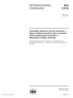
Figure 3 provides graphical information on the determination of the maximum to minimum range of
background noise.
L
L
The one-third-octave frequency spectrum measured according to IEC 61260–1, corresponding to the
reported maximum level of background noise shall be reported.
The peak to peak range o f the background noise, ∆ Lbgn,p-p , is determined by subtracting the lowest
background noise observed during the 10 s time interval from the largest background noise observed
during the 10 s time interval.
When reporting in one-third octaves is required, the background noise shall meet the requirements
given in 6.3.3.
Annex G gives measurement criteria for A-weighted sound pressure levels in flowchart form as an aid
to measurement and reporting results.
NOTE 1 Background noise measurements account for the variations in time at both microphones. The intent
o f the above statement is to capture the entire range o f variation experienced at the test facility to provide an
assessment o f the suitability o f the test facility to carry out the specified measurements.
NOTE 2
The range o f background noise, ∆ Lbgn,p-p , is specified to ensure the background noise is su fficiently
time invariant, meaning, in an acoustic sense the variation in sound pressure level vs. time is low enough, to
be able to apply the background corrections o f Table 2 to A-weighted sound pressure levels. One-third-octave
measurements do not have the necessary background noise time invariance to allow for compensation.
Key
1
2
3
X
Y
range o f the background noise level, ΔL bgn,p-p
maximum noise level during background noise check
minimum noise level during background noise check
time
background noise level
Figure 3 — Determination of the range of background noise
6.3.2
Vehicle A-weighted sound pressure level measurement correction criteria
Depending on the level and the range of maximum to minimum value of the representative background
noise A-weighted sound pressure level over a defined time period, the measured th test result within a
test condition, test, , shall be corrected according to Table 2 to obtain the background noise corrected
level testcorr, . Except where noted, testcorr, = test, - corr.
j
L
L
10
j
I n tern ati o n al Org an i z ati o n fo r S tan d ard i z ati o n
j
L
j
L
j
L
© ISO 2016 – All rights reserved
ISO 16254:2016(E)
Table 2 — Correction for level of background noise when measuring full vehicle A-weighted
sound pressure level
Correction for background noise
Range of maximum to
Sound pressure level of jth
minimum value of the
test result minus
representative background
background noise level,
noise A-weighted sound
∆ L = Ltest, - L bgn ,
pressure level over a
in dB
Correction,
L corr,
in dB
j
d
e
f
i
n
∆ Lbgn,p-p ,
e
d
t
i
m
e
p
e
r
i
in dB
Not applicable
≤2
o
d
,
∆ L ≥ 10
8 ≤ ∆ L < 10
6 ≤ ∆L < 8
4,5 ≤ ∆ L < 6
3 ≤ ∆ L < 4,5
∆ L < 3 dB
0
0,5
1,0
1,5
2,5
No valid measurement can
be reported
The trained technician should ensure that measurements are only per formed when there is no transient
disturbance that could potentially result in an inappropriate noise correction.
Background noise corrections to measurements are only valid when the range o f the maximum to
minimum background noise A-weighted sound pressure level is 2 dB or less. In all cases where the
range of the maximum to minimum background noise is greater than 2 dB, the maximum level of the
background noise shall be 10 dB or more below the level of the measurement. When the maximum to
minimum range of background noise is greater than 2 dB and the level of the background noise is less
than 10 dB below the measurement, no valid measurement is possible.
Background compensation is not permitted for one-third-octave-band measurements.
The use o f indoor test facilities may be necessary to achieve the specifications in this International
Standard.
Annex H gives correction criteria for A-weighted sound pressure levels in flowchart form as an aid to
measurement and reporting results.
NOTE
The requirements for margin between background noise and test results are given to maintain
an uncertainty o f 1 dB or less solely due to background noise. Total measurement uncertainty will include
uncertainty due to additional factors.
6.3.3
Background noise requirements when analysing in one-third-octave bands
When reporting one-third octaves according to this International Standard, the level of background
noise in each one-third-octave o f interest, analysed according to 6.3.1, shall be at least 6 dB below the
measurement o f the vehicle or external sound generation system under test in each one-third-octaveband of interest. The A-weighted sound pressure level of the background noise shall be at least 10 dB
below the measurement o f the vehicle or external sound generation system under test.
Background compensation is not permitted for one-third-octave-band measurements.
Annex I gives measurement criteria for 1/3 octave sound pressure levels in flowchart form as an aid to
measurement and reporting results.
NOTE
The requirements for margin between background noise and test results are given to maintain
an uncertainty o f 1 dB or less solely due to background noise. Total measurement uncertainty will include
uncertainty due to additional factors.
© ISO 2016 – All rights reserved
I n tern ati o n al Org an i z ati o n fo r S tan d ard i z ati o n
11
ISO 16254:2016(E)
6.3.4 Measurement background noise when testing a component
When measuring an external sound generation system separate from the vehicle as provided in this
International Standard, the background noise level shall be at least 10 dB lower than the measured
level of the component under test.
The background, or ambient noise, shall be measured for a duration of at least 10 s before and after a
series of component tests. A 10 s sample taken from this measurement shall be used to calculate the
reported background noise, taking account to ensure the 10-s sample selected is representative of the
background noise in absence o f any transient disturbance. The measurements shall be made with the
same microphones and microphone locations used during the test.
For measurements where narrowband results are reported, the narrowband background noise shall be
reported at the same frequency resolution as the measurement results.
7 Test procedures
7.1 Full vehicle testing
7.1.1
Microphone positions
The distance from the microphone positions on the microphone line PP′ to the perpendicular re ference
line CC′ as specified in Figure 1 on the test track or in an indoor test facility shall be 2,0 m ± 0,05 m.
The microphones shall be located 1,2 m ± 0,02 m above the ground level. The reference direction for free
field conditions as specified in IEC 61672–1 shall be horizontal and directed perpendicularly towards
the path o f the vehicle line CC′.
7.1.2
Conditions of the vehicle
7.1.2.1 General conditions
The vehicle shall be supplied as specified by the vehicle manu facturer.
Before the measurements are started, the vehicle shall be brought to its normal operating conditions.
7.1.2.2 Battery state of charge
I f so equipped, propulsion batteries shall have a state-of-charge su fficiently high to enable all key
functionalities according to the manu facturer’s specifications. Propulsion batteries shall be within
their component-temperature window to enable all key functionalities that could reduce vehicle noise
emissions. Any other type of rechargeable energy storage system shall be ready to operate during the test.
7.1.2.3 Accessory loads
If the vehicle is equipped with an internal combustion engine and a second source of propulsive power,
all vehicle loads that may automatically force an engine re-start or prevent engine shut down shall be
switched off.
All audio, entertainment, communication, and navigation systems shall be switched o ff.
NOTE Example loads could include air conditioning, defroster operation, window de-icing, seat heaters or
coolers, etc.
7.1.2.4 Multi-mode operation
If the vehicle is equipped with multiple driver selectable operating modes, the mode which provides the
lowest sound emission during the test conditions given in 7.1.5 shall be selected.
12
I n tern ati o n al Org an i z ati o n fo r S tan d ard i z ati o n
© ISO 2016 – All rights reserved
ISO 16254:2016(E)
When the vehicle provides multiple operating modes that are automatically selected by the vehicle,
it is the responsibility o f the manu facturer to determine the correct manner o f testing to achieve the
minimum sound emission.
In cases where it is not possible to determine the vehicle operating mode providing the lowest sound
emission, all modes shall be tested and the mode giving the lowest test result shall be used to report the
vehicle sound emission in accordance with this International Standard.
NOTE Modes include, but are not limited to: engine operation state (on or off), driver selectable operating
modes (sport, eco, winter, etc.), vehicle selectable operating modes (sport, eco, winter, etc.), and transmission
selection mode (sport, eco, winter, etc.). Modes do not include transmission gear selection such as park, drive,
reverse or neutral.
7.1.2.5
Vehicle non-pedestrian safety warning signals
No sound or noise source not related to pedestrian sa fety shall operate during the tests.
The purpose o f this requirement is to ensure no sound or noise source not related to pedestrian sa fety
shall operate during the test.
7.1.3
Test mass of vehicle
Measurements shall be made on vehicles at kerb mass +75 kg or mass in running order, as defined by
the manu facturer, with an allowable tolerance o f ±15 %.
7.1.4
Tyre selection and condition
The tyres for test are selected by the vehicle manu facturer and shall correspond to one o f the tyre sizes
and types designated for the vehicle by the vehicle manu facturer.
The tyres shall be inflated to the pressure recommended by the vehicle manu facturer for the test mass
of the vehicle.
NOTE
Tyre noise will contribute to the sound emission o f the vehicle at any speed over 0 km/h. At vehicle
speeds in excess o f 20 km/h, tyre noise will have a significant contribution to measured sound pressure levels.
7.1.5
Operating conditions
7.1.5.1
General conditions
The path o f the centreline o f the vehicle shall follow line CC′ as closely as possible throughout the entire
test, from the approach to line AA′ until the rear o f the vehicle passes line BB′. Any trailer, which is not
readily separable from the towing vehicle, shall be ignored when considering the crossing o f the line BB′.
7.1.5.2
Test speeds
The vehicle shall reach the test speed, vtest, when the front reference plane according to the definition
given in 3.1 is at line PP′. During the constant speed test, the acceleration control unit shall be positioned
to maintain a constant speed between AA′ and BB′. The vehicle shall be operated as defined by the
manufacturer for normal operation.
Normal operation may include shuto ff o f one or more propulsion sources.
7.1.5.3
7.1.5.3.1
Standstill conditions
General
The test speed,
vtest, shall
appropriate, on the PP′ line.
© ISO 2016 – All rights reserved
I n tern ati o n al Org an i z ati o n fo r S tan d ard i z ati o n
be 0 km/h with the front reference plane or rear reference plane, as
13
ISO 16254:2016(E)
If the vehicle is equipped with an internal combustion engine and a second source of propulsive power,
condition to allow engine shutdown, and before vehicle loads can force an engine re-start.
the stopped condition test measurement shall be made a fter a time delay from the vehicle stopped
7.1.5.3.2 Forward testing
For forward testing, the front re ference plane o f the vehicle shall be on the PP′ line.
7.1.5.3.3 Backing testing
For backing testing, the rear re ference plane o f the vehicle shall be on the PP′ line.
7.1.5.3.4 Manual transmission vehicle
The vehicle shall be tested in the appropriate standstill mode as defined in 7.1.2.4. The gear selector
shall be in a gear and the vehicle shall remain at 0 km/h for the duration of the test. The manufacturer
shall determine the appropriate condition for testing.
NOTE The common situation for stopped vehicle testing would be for a manual transmission vehicle to have
the gear selector in neutral. However, for the purpose of this test, the intention is to place the vehicle in a state
where it is ready to move.
7.1.5.3.5 Automatic transmission vehicle
The vehicle shall be tested in the appropriate standstill mode as defined in 7.1.2.4. The gear selector
shall be in the normal driving position for testing when the front reference plane of the vehicle is on the
PP′ line. The gear selector shall be in the reverse driving position for testing when the rear re ference
plane o f the vehicle is on the PP′ line. The vehicle shall remain at 0 km/h for the duration o f the test. The
manufacturer shall determine the appropriate condition for testing.
7.1.5.4 Slow speed cruise
7.1.5.4.1 General
I f a vehicle is tested in an indoor facility, the vehicle shall be located with the front or rear re ference
plane on the PP′ line, as appropriate. The vehicle A-weighted sound pressure level shall be measured for
a duration o f 5 s and reported. The one-third-octave frequency spectrum corresponding to the reported
maximum A-weighted sound pressure level shall be reported.
For the purpose o f measuring the per formance o f an external sound generation system, the sound
pressure level o f the vehicle may be measured with the vehicle at 0 km/h and external sound generation
system controlled as to simulate operation at 10 km/h.
7.1.5.4.2 Automatic transmission vehicle
The gear selector shall be placed as specified by the manu facturer for normal driving.
7.1.5.4.3 Manual transmission vehicle
The gear selector shall be placed in the highest gear which can achieve the target vehicle speed with
constant engine speed.
7.1.5.4.4 Forward testing at 10 km/h
The test speed, vtest, shall be 10 km/h ± 1 km/h between AA′ and PP′.
It is recommended that i f other vehicle speeds are specified in regulations, the per formance specification
given here can be modified to change the test speed, retaining all other specifications.
14
I n tern ati o n al Org an i z ati o n fo r S tan d ard i z ati o n
© ISO 2016 – All rights reserved
ISO 16254:2016(E)
7.1.6
Measurement readings and reported values
7.1.6.1
General
It is recommended that persons technically trained and experienced in current noise measurement
techniques select the test instrumentation and conduct the tests.
I f a sound peak obviously out o f character with the general sound pressure level is observed, that
measurement shall be discarded.
At least four measurements for all test conditions shall be made on each side of the vehicle and for each
mode tested.
The first four jth valid consecutive measurement results for any test condition, within 2,0 dB, allowing
for the deletion of non-valid results, shall be used for the calculation of the appropriate intermediate or
final result.
For measurement of a vehicle in motion (forward and backing) outdoors, the maximum A-weighted sound
pressure level indicated during each passage of the vehicle between AA′ and PP′ ( test, ) shall be noted for
L
j
each microphone position, to the first significant digit a fter the decimal place (for example, XX,X).
For measurement of a vehicle in motion indoor and in standstill (forward and backing), the maximum
A-weighted sound pressure level indicated during each period o f 5 s defined in 7.1.5.4.1 for each
microphone position, Ltest, , shall be noted, to the first significant digit a fter the decimal place (for
example, XX,X).
j
NOTE 1 Satis fying the criteria listed above requires evaluation o f measured sound pressure data vs. time to
select the appropriate time segments for proper analysis and reporting o f measured values according to this
International Standard.
NOTE 2 An intermediate result can be for one vehicle mode or operating condition.
7.1.6.2
Measurement of a vehicle in standstill conditions
This subclause specifies the requirements to measure the vehicle sound emission in standstill
conditions.
The vehicle sound pressure level shall be measured for a duration of 5 s.
For each maximum A-weighted sound pressure level for each microphone position, the corresponding
one-third-octave results for each microphone position shall be reported.
7.1.6.3
7.1.6.3.1
Measurement of a vehicle in motion
General
This subclause specifies the requirements to measure the vehicle sound emission in motion.
7.1.6.3.2
Outdoor testing
For each maximum A-weighted sound pressure level, the corresponding one-third-octave spectrum
shall be reported for each microphone position.
7.1.6.3.3
Indoor testing
The vehicle sound pressure level shall be measured for a duration of 5 s.
I f a sound peak obviously out o f character with the general sound pressure level is observed, that
measurement shall be discarded. The selected sound sample shall be representative of the vehicle
© ISO 2016 – All rights reserved
I n tern ati o n al Org an i z ati o n fo r S tan d ard i z ati o n
15
ISO 16254:2016(E)
minimum sound emission in the condition o f test in absence o f any transient disturbance. Ltest, for each
microphone position shall be corrected according to the criteria given in 6.3.2 to obtain Ltestcorr, .
j
j
For each maximum A-weighted sound pressure level, the corresponding one-third-octave spectrum
shall be reported for each microphone position.
7.1.7
Data compilation
7.1.7.1 Maximum A-weighted sound pressure level data compilation
For a given test condition and mode (see 7.1.2.4), the background-corrected results,
runs shall be averaged separately for each side.
L
testcorr,
j
of the
The reported A-weighted sound pressure level is the lower value of the two averages, rounded to the
nearest integer.
7.1.7.2 One-third-octave sound pressure level data compilation
The one-third-octave reported spectrum shall be the arithmetic average of the four individual run onethird-octave spectra corresponding to the maximum A-weighted sound pressure level on each side for
each individual measurement run.
The final one-third-octave spectra, measured according to IEC 61260–1, to be reported are the spectra
corresponding to the same side as the reported A-weighted sound pressure level.
No background correction shall be applied to any measured one-third-octave result.
Any one-third-octave spectrum measured when the conditions o f 6.3.3 are not satisfied may only be
reported for information and the measurement uncertainties given in Table 4 are not valid.
7.1.8
Standstill results
The Lst,fwd and Lst,rev value for each mode according to 7.1.2.4 shall be the result from 7.1.5.3 using the
definitions given in 7.1.6.
I f one-third-octave bands are analysed, they shall use the result given in 7.1.7.2.
7.1.9
Slow speed cruise result at 10 km/h
The crs,10 value for each mode according to 7.1.2.4 shall be the result from 7.1.5.4 using the definitions
given in 7.1.6.
I f one-third-octave bands are analysed, they shall use the result given in 7.1.7.2.
L
7.1.10 Reported value
The reported value crs,10 , st,rev and
for each mode according to 7.1.2.4.
L
L
L
st,fwd shall be the minimum of the L crs,10 , L st,rev and L st,fwd, values
7.2 Measurement of sound to determine frequency shift
7.2.1
General
The specifications contained in these sections are intended to measure the emitted acoustic in formation
from an external sound generation system installed for purposes o f providing acoustic in formation to
pedestrians in the near vicinity o f a vehicle. The in formation so measured characterizes the frequencies
emitted by the system, as well as the change in frequency as a function o f vehicle operating parameters.
No background correction shall be applied to any measured result.
16
I n tern ati o n al Org an i z ati o n fo r S tan d ard i z ati o n
© ISO 2016 – All rights reserved
ISO 16254:2016(E)
See Annex B for further in formation on frequency shi ft.
7.2.2
Instrumentation
The entire acoustic measurement system including microphone(s) and any subsequent measurement
apparatus shall fulfil the requirements o f IEC 61672–1, class 1 sound level meter.
The digital sound recording system shall have at least a 16 bit quantization. The sampling rate, Fs , and
the dynamic range shall be appropriate to the signal o f interest.
NOTE
No specific requirements have been given for sampling rate due to the wide range o f signal frequency
content that may be analysed. It is expected that knowledgeable and trained personnel will select appropriate
sampling rates.
7.2.3
Signal processing requirements
The frequency resolution, ∆ f, o f the measurement shall be su fficiently precise to di fferentiate between
the frequencies at the various test conditions. The sound analysis system shall be capable o f per forming
discrete Fourier trans form and auto power spectrum analysis at a frequency resolution and over the
frequency range containing all frequencies o f interest. The block size, N, used for subsequent signal
processing shall enable the required ∆ f, where ∆ f ≤ Fs/N.
Analyser settings shall be determined by the user to provide data according to these requirements.
7.2.4
Test facilities
7.2.4.1
Vehicle test facilities
The test facility shall meet the requirements given in 6.1.2 or 6.1.3.
7.2.4.2
Component test facilities
The test facility shall meet the requirements given in 6.1.4.
The sound emitting component o f the external sound generation system is recommended to be mounted
0,5 m above a reflecting plane (floor) o f the test space. The primary propagation axis o f the sound
emitting component shall be oriented horizontal to the reflecting plane.
The microphone is recommended to be located 1,0 m from the centre of the component at a height of 0,5 m.
NOTE
Specific recommendations have been given for placement o f the external sound generation system and
the microphone within the test facility to provide guidance for success ful testing. There are other arrangements
o f the external sound generation system and microphone that can be e ffective to measure frequency content.
7.2.5
Frequency shift measurement test procedure
7.2.5.1
7.2.5.1.1
General
Frequency shift measurements
The frequency shi ft shall be measured by a vehicle, a simulated vehicle operation, or a component based
test procedure.
7.2.5.1.2
Full vehicle operation
The vehicle shall be installed in an indoor test facility where the vehicle can operate in the same
manner as outdoors. All microphone locations shall be as for the full vehicle test conditions as specified
in Figure 1 . The front plane of the vehicle shall be on the PP′ line.
© ISO 2016 – All rights reserved
I n tern ati o n al Org an i z ati o n fo r S tan d ard i z ati o n
17
ISO 16254:2016(E)
Outdoor variant: The vehicle shall be operated in the same outdoor test facility and according to the
same general operating condition as for the full vehicle testing (see 7.1). The microphone shall be
installed on board o f the vehicle in the direct vicinity o f the emitting sur face o f the external sound
generating system. The acquisition system shall be installed on board o f the vehicle.
A frequency, f , shall be identified that is intended to change as a function o f vehicle speed, which can be
measured and can be tracked for operating conditions specified in this International Standard.
i
Special care shall be taken to carry out the frequency shi fting measurements in outdoor facilities with
the vehicle in motion. The signal intended to be measured should not be masked by other vehicle or
background noise.
NOTE 1
Typical signal analysis tools provide frequency vs. speed o f the tonal component(s) that correspond
with vehicle speed.
NOTE 2 No specific frequency identification process has been specified as there is no known identification
specification that can clearly identi fy frequencies which shi ft with vehicle operating conditions, primarily vehicle
speed, when the frequency content o f the desired signal and any background noise is unknown. See Annex B for
further information.
NOTE 3 It is understood when using an indoor test facility that the vehicle will remain in position relative to
the microphones. This is for the purpose to provide an acoustically stationary signal for subsequent analysis and
reporting of results.
On board microphones do not have relative motion from the sound generation system and deliver a
more reliable signal for frequency shi fting measurement. For on-board microphone installed in the
direct vicinity o f the emitting sur face o f the external sound generating system, it is recommended
— to position the microphones on the axis (i f it exists) o f the acoustic emission o f the system;
— at a distance o f 8 cm from the emitting sur face: not too far to be influenced by other sound sources,
and not too close to have no any distorted signal;
— to use a decoupling attachment device between microphone and vehicle body.
Special care shall be taken to per form the frequency shi fting measurements in indoor facilities with the
tyres rotating. This is due to the contaminating signal from the tyre/roll inter face.
7.2.5.1.3
Simulated vehicle operation (for indoor or outdoor)
The vehicle shall be operated in a test facility where the vehicle can accept an external vehicle speed
signal simulating vehicle operation. All microphone locations shall be as for the full vehicle test
conditions as specified in Figure 1 . The front re ference plane o f the vehicle shall be on the PP′ line.
A frequency, f , shall be identified that is intended to change as a function o f vehicle speed, which can be
measured and can be tracked for operating conditions specified in this International Standard.
i
NOTE 1
Typical signal analysis tools provide frequency vs. speed o f the tonal component(s) that correspond
with vehicle speed.
NOTE 2 No specific frequency identification process has been specified as there is no known identification
specification that can clearly identi fy frequencies which shi ft with vehicle operating conditions, primarily vehicle
speed, when the frequency content o f the desired signal and any background noise is unknown. See Annex B for
further information.
NOTE 3 It is understood when using an indoor test facility that the vehicle will remain in position relative to
the microphones. This is for the purpose to provide an acoustically stationary signal for subsequent analysis and
reporting o f results. The use o f the simulated operation further removes potentially inter fering noise due to the
tyre/road interaction.
18
I n tern ati o n al Org an i z ati o n fo r S tan d ard i z ati o n
© ISO 2016 – All rights reserved
ISO 16254:2016(E)
7.2.5.1.4
Component test procedure
A frequency, f , shall be identified that is expected to change as a function o f vehicle speed, which can be
measured and can be tracked for operating conditions specified in this International Standard.
i
NOTE
Typical signal analysis tools provide frequency vs. speed o f the tonal component(s) that correspond
7.2.5.2
Measurement procedure
with vehicle speed.
The frequency characteristics o f the sound shall be measured together with an input signal to the
external sound generation system corresponding to the re ference vehicle speed.
The sound output o f the system shall be measured as follows.
— Record at least 5 s of the sound at a constant vehicle speed.
— Using a Hanning window, calculate the autopower o f the signal with a frequency resolution o f at
least 1 Hz using at least 66,6 % overlap averages from the 5 s time signal.
The frequencies, ,speed, of the external sound generation system signal shall be measured and recorded.
The corresponding vehicle speeds, ,speed and ,ref, shall be measured and recorded.
Calculate _ , the frequency shi ft of the external sound generation system signal according to
Formula (1):
= {[( ,speed - fi,ref)/( test - ref)]/ ,ref} · 100
(1)
fi
fi
fi
del f
del_ f
fi
v
v
fi
where
,speed is the frequency at a given speed value;
f ,ref
is the frequency at the re ference speed value;
fi
i
v
test
v
ref
is the vehicle velocity, actual or simulated, corresponding to the frequency f ,speed;
i
is the vehicle velocity, actual or simulated, corresponding to the frequency f ,ref.
i
Formula (1) is only valid when the actual vehicle speed,
speed, ref.
Results shall be reported using Table 3.
v
v
test,
is higher than the reference vehicle
Table 3 — Vehicle speed for measurement to determine frequency shift
Reported speed
Frequency, f ,speed , left side
Frequency, f ,speed , right side
Frequency shi ft, le ft side
Frequency shi ft, right side
i
i
km/h
Hz
Hz
%
%
5 km/h
(Reference)
Test results at target speeds
10 km/h
15 km/h
20 km/h
n.a.
n.a.
The reference speed should be 5 km/h unless other speeds are desired.
© ISO 2016 – All rights reserved
I n tern ati o n al Org an i z ati o n fo r S tan d ard i z ati o n
19