Tiêu chuẩn iso 17657 2 2005
Bạn đang xem bản rút gọn của tài liệu. Xem và tải ngay bản đầy đủ của tài liệu tại đây (187.15 KB, 18 trang )
INTERNATIONAL
STANDARD
ISO
17657-2
First edition
2005-09-15
Resistance welding — Welding current
measurement for resistance welding —
Part 2:
Welding current meter with current
sensing coil
Soudage par résistance — Mesurage des courants en soudage par
résistance —
--`,,```,,,,````-`-`,,`,,`,`,,`---
Partie 2: Ampèremètre avec tore de mesure de courant
Reference number
ISO 17657-2:2005(E)
Copyright International Organization for Standardization
Reproduced by IHS under license with ISO
No reproduction or networking permitted without license from IHS
© ISO 2005
Not for Resale
ISO 17657-2:2005(E)
PDF disclaimer
This PDF file may contain embedded typefaces. In accordance with Adobe's licensing policy, this file may be printed or viewed but
shall not be edited unless the typefaces which are embedded are licensed to and installed on the computer performing the editing. In
downloading this file, parties accept therein the responsibility of not infringing Adobe's licensing policy. The ISO Central Secretariat
accepts no liability in this area.
Adobe is a trademark of Adobe Systems Incorporated.
Details of the software products used to create this PDF file can be found in the General Info relative to the file; the PDF-creation
parameters were optimized for printing. Every care has been taken to ensure that the file is suitable for use by ISO member bodies. In
the unlikely event that a problem relating to it is found, please inform the Central Secretariat at the address given below.
© ISO 2005
All rights reserved. Unless otherwise specified, no part of this publication may be reproduced or utilized in any form or by any means,
electronic or mechanical, including photocopying and microfilm, without permission in writing from either ISO at the address below or
ISO's member body in the country of the requester.
ISO copyright office
Case postale 56 • CH-1211 Geneva 20
Tel. + 41 22 749 01 11
Fax + 41 22 749 09 47
Web www.iso.org
Published in Switzerland
ii
--`,,```,,,,````-`-`,,`,,`,`,,`---
Copyright International Organization for Standardization
Reproduced by IHS under license with ISO
No reproduction or networking permitted without license from IHS
© ISO 2005 – All rights reserved
Not for Resale
ISO 17657-2:2005(E)
--`,,```,,,,````-`-`,,`,,`,`,,`---
Contents
Page
Foreword............................................................................................................................................................ iv
Introduction ........................................................................................................................................................ v
1
Scope ..................................................................................................................................................... 1
2
Normative references ........................................................................................................................... 1
3
Terms and definitions........................................................................................................................... 1
4
Physical environment and operating conditions .............................................................................. 2
5
5.1
5.2
Classification of welding current meters with their current sensing coil, and designation
of product .............................................................................................................................................. 2
Classes of welding current meter with current sensing coil ........................................................... 2
Designation of product......................................................................................................................... 3
6
6.1
6.2
6.3
6.4
6.5
6.6
6.7
6.8
6.9
6.10
6.11
6.12
6.13
6.14
6.15
6.16
6.16.1
6.16.2
Requirements for welding current meter with current sensing coil................................................ 3
Welding current meter.......................................................................................................................... 3
Current sensing coil ............................................................................................................................. 3
Welding current meter with its current sensing coil......................................................................... 4
Integrator ............................................................................................................................................... 4
Data processing unit ............................................................................................................................ 4
Display unit and output ports.............................................................................................................. 4
Minimum and maximum duration of welding current ....................................................................... 4
Maximum measuring current............................................................................................................... 5
Minimum measuring current ............................................................................................................... 5
Phase-controlled current ..................................................................................................................... 5
Minimum time for current measurement ............................................................................................ 5
Fluctuation of supply voltage.............................................................................................................. 5
Mechanical strength of current sensing coil ..................................................................................... 5
Setting position error of current sensing coil ................................................................................... 5
Influence of ambient temperature ....................................................................................................... 5
Test......................................................................................................................................................... 6
Type test ................................................................................................................................................ 6
Acceptance test .................................................................................................................................... 6
7
7.1
7.2
7.3
7.4
7.5
7.6
Test procedures .................................................................................................................................... 6
Maximum measuring current............................................................................................................... 6
Minimum measuring current ............................................................................................................... 6
Phase-controlled current ..................................................................................................................... 7
Minimum time for current measurement ............................................................................................ 7
Fluctuation of supply voltage.............................................................................................................. 7
Thermal test........................................................................................................................................... 8
8
Marking .................................................................................................................................................. 8
Annex A (normative) Definition of indicated measuring time and its indicated current value .................. 9
A.1
Indicated measuring time .................................................................................................................... 9
A.2
Welding current value for the indicated measuring time ............................................................... 10
Annex B (informative) Set-up of a current sensing coil and construction of welding current
meters .................................................................................................................................................. 11
iii
© ISO 2005 – All rights reserved
Copyright International Organization for Standardization
Reproduced by IHS under license with ISO
No reproduction or networking permitted without license from IHS
Not for Resale
ISO 17657-2:2005(E)
--`,,```,,,,````-`-`,,`,,`,`,,`---
Foreword
ISO (the International Organization for Standardization) is a worldwide federation of national standards bodies
(ISO member bodies). The work of preparing International Standards is normally carried out through ISO
technical committees. Each member body interested in a subject for which a technical committee has been
established has the right to be represented on that committee. International organizations, governmental and
non-governmental, in liaison with ISO, also take part in the work. ISO collaborates closely with the
International Electrotechnical Commission (IEC) on all matters of electrotechnical standardization.
International Standards are drafted in accordance with the rules given in the ISO/IEC Directives, Part 2.
The main task of technical committees is to prepare International Standards. Draft International Standards
adopted by the technical committees are circulated to the member bodies for voting. Publication as an
International Standard requires approval by at least 75 % of the member bodies casting a vote.
Attention is drawn to the possibility that some of the elements of this document may be the subject of patent
rights. ISO shall not be held responsible for identifying any or all such patent rights.
ISO 17657-2 was prepared by Technical Committee ISO/TC 44, Welding and allied processes, Subcommittee
SC 6, Resistance welding.
ISO 17657 consists of the following parts, under the general title Resistance welding — Welding current
measurement for resistance welding:
Part 1: Guidelines for measurement
Part 2: Welding current meter with current sensing coil
Part 3: Current sensing coil
Part 4: Calibration system
Part 5: Verification of welding current measuring system
iv
Copyright International Organization for Standardization
Reproduced by IHS under license with ISO
No reproduction or networking permitted without license from IHS
© ISO 2005 – All rights reserved
Not for Resale
ISO 17657-2:2005(E)
Introduction
--`,,```,,,,````-`-`,,`,,`,`,,`---
Requests for official interpretations of any aspect of this part of ISO 17657 should be directed to the
Secretariat of ISO/TC 44/SC 6 via your national standards body. A complete listing of these bodies can be
found at .
v
© ISO 2005 – All rights reserved
Copyright International Organization for Standardization
Reproduced by IHS under license with ISO
No reproduction or networking permitted without license from IHS
Not for Resale
--`,,```,,,,````-`-`,,`,,`,`,,`---
Copyright International Organization for Standardization
Reproduced by IHS under license with ISO
No reproduction or networking permitted without license from IHS
Not for Resale
INTERNATIONAL STANDARD
ISO 17657-2:2005(E)
Resistance welding — Welding current measurement for
resistance welding —
1
--`,,```,,,,````-`-`,,`,,`,`,,`---
Part 2:
Welding current meter with current sensing coil
Scope
This part of ISO 17657 specifies a welding current meter with a current sensing coil to measure the weld time
and the r.m.s. value of the welding current during a certain interval using single-phase alternating current of
frequency of 50 Hz or 60 Hz, or direct current.
This part of ISO 17657 is applicable for a welding current measuring system, with a display or calibrated
output port, which may be connected to a welding controller.
2
Normative references
The following referenced documents are indispensable for the application of this document. For dated
references, only the edition cited applies. For undated references, the latest edition of the referenced
document (including any amendments) applies.
ISO 669, Resistance welding — Resistance welding equipment — Mechanical and electrical requirements
ISO 17657-1:2005, Resistance welding — Welding current measurement for resistance welding — Part 1:
Guidelines for measurement
ISO 17657-3:2005, Resistance welding — Welding current measurement for resistance welding — Part 3:
Current sensing coil
ISO 17657-4:2005, Resistance welding — Welding current measurement for resistance welding — Part 4:
Calibration system
3
Terms and definitions
For the purposes of this document, the terms and definitions given in ISO 669 and the following apply.
3.1
minimum measuring time
minimum settable value of the measuring time
See Figure A.1.
3.2
maximum measuring time
maximum settable value of the measuring time, which will depend on the types of component making up the
welding current meter
See Figure A.1.
1
© ISO 2005 – All rights reserved
Copyright International Organization for Standardization
Reproduced by IHS under license with ISO
No reproduction or networking permitted without license from IHS
Not for Resale
ISO 17657-2:2005(E)
3.3
indicated measuring time
duration of measuring time, from start time to finish time, while the welding current is flowing
NOTE
Normally the start and finish times for measuring current flow are automatically set. If the start time is set at
zero or at a value greater than zero, and the finish time is set at a smaller value than the weld time, as shown in Figure A.1,
then the welding current is calculated for the measuring duration between the start time and the finish time.
3.4
automatic zero level correction
device that allows removal of the effect of zero drift of output when direct welding current measurement is
incorporated
3.5
drift
amount of shift in the zero position
3.6
measuring accuracy
scatter limit of indicated or output values permissible, which is indicated against the full scale value
4
Physical environment and operating conditions
Unless otherwise specified, the welding current meter shall be capable of operating under the following
conditions without any adverse effect on its accuracy:
at an ambient air temperature between of +5 °C and +40 °C;
in relative humidity up to 95 %;
at altitudes up to 1 000 m above mean sea level;
where gas, fine dust, oil mist, spatters, etc. are included in the air such as those caused by ordinary arc or
spot welding work.
When the operating conditions deviate from those specified above, an agreement shall be made between the
manufacturer and the purchaser.
5 Classification of welding current meters with their current sensing coil, and
designation of product
5.1
Classes of welding current meter with current sensing coil
Table 1 — Classification of welding current meters with current sensing coil by measuring accuracy
Classification
Measuring accuracy
Application
Highly accurate class
± 1,0 % of full scale
Laboratory use
Accurate class
± 2,0 % of full scale
Routine use for highly accurate systems
Ordinary class
± 5,0 % of full scale
Routine use for ordinary systems
2
Copyright International Organization for Standardization
Reproduced by IHS under license with ISO
No reproduction or networking permitted without license from IHS
© ISO 2005 – All rights reserved
Not for Resale
--`,,```,,,,````-`-`,,`,,`,`,,`---
Welding current meters with their current sensing coil are classified as in Table 1 depending on the measuring
accuracy.
ISO 17657-2:2005(E)
5.2
Designation of product
The following shall be indicated:
current type that can be measured i.e. alternating current and/or direct current;
maximum current measurable;
specified accuracy as a welding current meter.
EXAMPLE 1
of 15 kA.
Only single-phase alternating current measurable, ordinary class, and maximum measuring current value
15 kA ac class 5.0
EXAMPLE 2
Single-phase alternating current and direct current measurable, accurate class, and maximum measuring
current value of 20 kA.
20 kA ac/dc class 2.0
6
6.1
Requirements for welding current meter with current sensing coil
Welding current meter
The welding current meter shall consist of a data processing unit, and a display of the welding current and
weld time. An example of the construction is illustrated in Annex B.
The welding current shall be indicated as at least the true r.m.s. (root-mean-square) value. The weld time
should be counted on a cycle basis or the length indicated in milliseconds, calculated as the product of the
length of 1 cycle and the number of cycles.
Welding current meters alone (without the current sensing coil) are classified as in Table 2 depending on the
measuring accuracy.
Table 2 — Requirements for measuring accuracy of welding current meters
Classification
Measuring accuracy
Application
Highly accurate class
± 0,5 % of full scale
Laboratory use
Accurate class
± 1,0 % of full scale
Routine use for highly accurate systems
Ordinary class
± 2,0 % of full scale
Routine use for ordinary systems
The scatter shall be checked against the rated value of the test welding current meter in accordance with the
test procedures specified in ISO 17657-4.
6.2
Current sensing coil
The current sensing coil shall conform to requirements described in ISO 17657-3. The conversion coefficient
of the current sensing coil should coincide with requirements of the integrator built into the welding current
meter, and the value of the low-inductive output resistor shall meet the requirement specified by the supplier
for the current sensing coil itself.
--`,,```,,,,````-`-`,,`,,`,`,,`---
© ISO 2005 – All rights reserved
Copyright International Organization for Standardization
Reproduced by IHS under license with ISO
No reproduction or networking permitted without license from IHS
Not for Resale
3
ISO 17657-2:2005(E)
6.3
Welding current meter with its current sensing coil
The error of the welding current meter with its coil should be adjusted together with that of the welding current
meter and its current sensing coil. If it is necessary to change the current sensing coil, the welding current
measuring system shall be calibrated with a reference welding current measuring system.
The error of welding current measuring system should be calculated with the sum of both error values of the
welding current meter and its current sensing coil, or determined by measurements for a welding current
meter with its current sensing coil.
The maximum error of welding current measuring systems within the measuring range shall be within the
measuring accuracy stipulated in Table 1 corresponding to required class.
6.4
Integrator
The integrator for processing the output signal from the current sensing coil shall be designed to allow the
measurement of at least full-wave alternating current and heat-controlled alternating current. The output signal
should not be clipped or distorted by the supply voltage to the integrator.
NOTE
When the welding current meter is applied for measuring the medium-frequency alternating current or
medium-frequency direct current, an agreement may be needed between the manufacturer and the purchaser.
6.5
Data processing unit
The data processing unit consists of at least an analog-digital converter, memories and CPU. The values shall
be kept in the memory until the next measurement.
The computing algorithm shall be designed to obtain a true r.m.s. value of the welding current. The start time
and finish time used for the calculation shall comply with Annex A to this part of ISO 17657 and to
ISO 17657-1:2005.
Annex A to this part of ISO 17657 and to ISO 17657-1:2005 shall also be referred to in order to calculate the
welding current value for the weld time and for an indicated measuring time.
6.6
Display unit and output ports
The welding current meter should be built with a display device, either of the pointer type, the digital display
type or print-out type, indicating the measured welding current and weld time defined in ISO 17657-1, and
show the welding current value for an indicated measuring time. The current flow time should be automatically
determined in the case of direct current measurements.
The time unit for input of all time values in alternating current mode shall be controlled at least in one cycle
unit of the frequency of power source. In direct current mode, however, a millisecond unit may be used in
addition to, or as an alternative to cycles.
The welding current meter may have some output ports for welding current waveform as an analog output
signal, and the values of welding current and weld time etc. as digital signals.
Minimum and maximum duration of welding current
Measuring duration of welding current shall be determined based on the start and finish times of measurement
as illustrated in Annex A.
The start and finish times for direct welding current shall comply with the principle of Figure A.1 and of
Annex A in ISO 17657-1:2005.
4
Copyright International Organization for Standardization
Reproduced by IHS under license with ISO
No reproduction or networking permitted without license from IHS
© ISO 2005 – All rights reserved
Not for Resale
--`,,```,,,,````-`-`,,`,,`,`,,`---
6.7
ISO 17657-2:2005(E)
6.8
Maximum measuring current
Measuring accuracy for the maximum measuring current indicated on the nameplate shall comply with those
shown in Table 1 provided it is measured according to the method described in 7.1 using full-wave alternating
current.
6.9
Minimum measuring current
Measuring accuracy for 30 % (± 5 %) current of the maximum measuring current indicated on the nameplate
shall comply with those shown in Table 1 provided it is measured according to the method described in 7.2
using full-wave current.
6.10 Phase-controlled current
A measuring accuracy for a phase-controlled alternating current with a firing angle of 60° (± 10°) shall comply
with those shown in Table 1 according to the method described in 7.3 for a welding current value of each full
scale of the welding current meter.
NOTE
This requirement may be amended if there is an agreement between the manufacturer and the purchaser.
6.11 Minimum time for current measurement
A measuring accuracy of the welding current meter shall comply with those shown in Table 1 provided the
welding current is measured in the minimum measuring time indicated on the nameplate according to the
method described in 7.4.
6.12 Fluctuation of supply voltage
If the fluctuation in supply voltage to the welding current meter is up to ±10 %, or battery voltage is within a
permissible value, measuring accuracy of the welding current values shall comply with those shown in Table 1
when measurements are made using the method described in 7.5. Furthermore, a device shall be used to
indicate any voltage drop in the power supply below the permissible value of the welding current meter and it
should be capable of indicatiing when to use a battery.
6.13 Mechanical strength of current sensing coil
If the current sensing coil is subjected to a mechanical test as described in ISO 17657-3, then after the test,
the measuring accuracy shall comply with those stipulated in Table 1.
6.14 Setting position error of current sensing coil
Measuring accuracy shall be checked with the test procedure described in 7.4 of ISO 17657-3:2005, and the
deviation shall be recorded. The maximum measuring accuracy value shall comply with those shown in
Table 1.
6.15 Influence of ambient temperature
If the welding current meter is subjected to a temperature test as described in 7.6, then the measuring
accuracy for the maximum measuring current of the welding current meter indicated on the nameplate shall
comply with those shown in Table 1. The tests shall be performed using the method described in 7.1 in not
less than 95 % full-wave current.
--`,,```,,,,````-`-`,,`,,`,`,,`---
5
© ISOfor2005
– All rights reserved
Copyright International Organization
Standardization
Reproduced by IHS under license with ISO
No reproduction or networking permitted without license from IHS
Not for Resale
ISO 17657-2:2005(E)
6.16 Test
6.16.1 Type test
The following type tests shall be carried out according to procedures specified in Clause 7, results of which
shall comply with requirements specified in Clauses 5 and 6:
construction;
b)
minimum and maximum duration of welding current;
c)
maximum measuring current test;
d)
minimum measuring current test;
e)
phase-controlled current test;
f)
minimum measuring time test;
g)
fluctuation test of supply voltage;
h)
mechanical tests of current sensing coil;
i)
positioning test of current sensing coil;
j)
thermal test.
--`,,```,,,,````-`-`,,`,,`,`,,`---
a)
6.16.2 Acceptance test
Acceptance of a particular welding current meter with its coil shall be based on the above tests with the order
of priority as listed in 6.16.1. However, some or all of items a), b), c) and e) can be omitted by agreement
between the contracting parties.
7
7.1
Test procedures
Maximum measuring current
The measuring accuracy of the welding current meter with its coil, for the maximum measuring current should
be checked with a reference welding current measuring system in supplying 90 % to 100 % current of the
maximum indicated value of the meter. When using the welding current meter for single-phase alternating
current, the welding current meter with its coil shall be checked at 95 % or greater of full-wave current. A
welding current meter applicable to direct current shall be checked in the maximum measuring time. The fixing
part of the current sensing coil shall be set at position B, D or F shown in Figure 1 a) and the secondary
conductor shall be located at the centre of the current sensing coil as shown in Figure 1 b).
7.2
Minimum measuring current
The measuring accuracy of the welding current meter with its coil, for the minimum measuring current should
be checked with a reference welding current measuring system in supplying 30 % (± 5 %) of the maximum
indicated value of the meter. When using the welding current meter for single phase alternating current, the
welding current meter with its coil shall be checked at 95 % or greater of full-wave current. A welding current
meter applicable to direct current should be checked at the maximum measuring time. The fixing part of the
current sensing coil shall be set at position B, D or F shown in Figure 1 a) and the secondary conductor shall
be located at the centre of the current sensing coil as shown in Figure 1 b).
6
Copyright International Organization for Standardization
Reproduced by IHS under license with ISO
No reproduction or networking permitted without license from IHS
© ISO 2005 – All rights reserved
Not for Resale
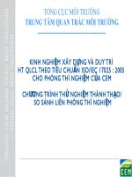
a) Positions A to G (secondary conductor
contacts to the coil)
b) Position H (secondary conductor located at
the centre of coil)
Key
1
2
secondary conductor (return)
secondary conductor
3
4
current sensing coil
lead cable
5
fixing
A to G fixing positions
Figure 1 a) shows position D used.
--`,,```,,,,````-`-`,,`,,`,`,,`---
ISO 17657-2:2005(E)
Figure 1 — Examples of the arrangement of a current sensing coil and their position numbers
7.3
Phase-controlled current
The measuring accuracy of the welding current meter with its coil, in the maximum indicated value of the
meter, shall be checked with a reference welding current measuring system in supplying a phase-controlled
current with a firing angle of 60° (± 10°). The specification is only applicable to alternating current. The fixing
part of the current sensing coil shall be set at position B, D or F shown in Figure 1 a) and the secondary
conductor shall be located at the centre of the current sensing coil as shown in Figure 1 b).
7.4
Minimum time for current measurement
The measuring accuracy of the welding current meter with its coil at the minimum measuring time indicated on
the nameplate shall be checked with a reference welding current measuring system in supplying 90 % (± 5 %)
of the maximum scale reading of the current meter, and at the minimum measuring time.
7.5
Fluctuation of supply voltage
For welding current meters with their coils, suitable for measurement of single-phase alternating current only,
full-wave conduction shall be used:
a)
alternating current power supply: the measuring accuracy shall be checked for input power supply
fluctuations of −10 % and +10 %, by using a reference welding current measuring system;
b)
battery supply: the measuring accuracy shall be checked for changing the battery power supply at the
permissible limit value of battery voltage.
7
© ISO 2005 – All rights reserved
Copyright International Organization for Standardization
Reproduced by IHS under license with ISO
No reproduction or networking permitted without license from IHS
Not for Resale
ISO 17657-2:2005(E)
7.6
Thermal test
Tests described in 7.1 shall be carried out after maintaining the welding current meter and its current sensing
coil in a temperature-controlled oven for one hour, until the peripheral temperature reaches test temperature.
The thermal test shall be carried out at both +5 °C and +40 °C. The test shall be completed within three
minutes of removal from the oven.
8
Marking
The welding current meter shall be marked with following indications:
a)
name of the current meter;
b)
type(s) of welding current;
c)
maximum measuring current (kA);
d)
minimum time for current measurement (ms or number of cycles);
e)
maximum time for current measurement (ms or number of cycles);
f)
threshold level for measuring direct welding current in effective value to determine the weld time (%),
(applicable only for direct current measuring system);
g)
rated value of supply voltage for welding current meter (power source line voltage or battery voltage);
h)
power supply frequency for welding machine (Hz);
i)
date of manufacture;
j)
manufacturer’s name or its abbreviation;
k)
accuracy class for welding current meter with its coil;
l)
type of coil;
m) coil sensitivity;
n)
coil class.
--`,,```,,,,````-`-`,,`,,`,`,,`---
8
Copyright International Organization for Standardization
Reproduced by IHS under license with ISO
No reproduction or networking permitted without license from IHS
© ISO 2005 – All rights reserved
Not for Resale
ISO 17657-2:2005(E)
Annex A
(normative)
Definition of indicated measuring time and its indicated current value
A.1 Indicated measuring time
The calculation shall be performed in a whole-number multiple of each cycle duration of 50 Hz or 60 Hz
depending on the frequency of power supply when measuring alternating current, and which shall be applied
even in measuring the heat-controlled current. The calculation time for direct current should equate to a
whole-number multiple of either one half cycle or one cycle depending on the frequency of power source even
for direct current.
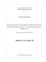
Examples of definitions of indicated measuring time are shown in Figure A.1.
a) Single-phase alternating current
b) Direct current
tb
measuring start time
te
measuring finish time
tf
integration finish time
ts
integration start time
t1
measuring time
t
integration time
Figure A.1 — Examples of the indicated measuring time
9
© ISO 2005 – All rights reserved
Copyright International Organization for Standardization
Reproduced by IHS under license with ISO
No reproduction or networking permitted without license from IHS
--`,,```,,,,````-`-`,,`,,`,`,,`---
where
Not for Resale
ISO 17657-2:2005(E)
A.2 Welding current value for the indicated measuring time
The current value is displayed with an effective value accumulated from the start time ts until finish time tf of
the measuring duration. The computation is achieved using equation (A.1).
tf 2
∫ ts i
i r.m.s. =
dt
(A.1)
te − tb
Where, the time t and t1 defined as follows:
t = tf − ts
(A.2)
t1 = t e − t b
(A.3)
The integration for the square of current value in alternating current is achieved only from ts to tf and it is
normalized by the time length (te − tb) counted in the half cycle (1/100 s or 1/120 s) unit to obtain the effective
value. While in direct current measurement, the integrating time, t, is the same as the time, t1, for the
normalization.
The definitions of t and t1 are shown in Table A.1.
Table A.1 — Times used for integration
Type of
current
t
t1
ac
Defined in Figure A.1 a)
t = tf − ts
[Cycle number defined in Figure A.1 a)] × (the length of 1 cycle time)a
t1 = t e − t b
dc
Defined in Figure A.1 b)
t = tf − ts
Same value as the left definition
t1 = t f − t s
a
The length of 1 cycle time with alternating current = 1/50 s for 50 Hz or = 1/60 s for 60 Hz.
When calculating the welding current value in alternating current measurement, ts is set to zero and tb, tf and
te are set by the following values:
tb
is set by the current start time shown in ISO 17657-1:2005, Annex A;
tf
is set by the current finish time shown in ISO 17657-1:2005, Annex A;
te
is set by the time calculated by multiplying the number of cycles by the length of 1 cycle (see
ISO 17657-1:2005, Annex A).
When calculating the welding current value in direct current measurement, ts and tb are set by the current start
time and tf and te are set by the current finish time shown in ISO 17657-1:2005, Figure A.1.
--`,,```,,,,````-`-`,,`,,`,`,,`---
10 Organization for Standardization
Copyright International
Reproduced by IHS under license with ISO
No reproduction or networking permitted without license from IHS
© ISO 2005 – All rights reserved
Not for Resale
ISO 17657-2:2005(E)
Annex B
(informative)
Set-up of a current sensing coil and construction of welding current
meters
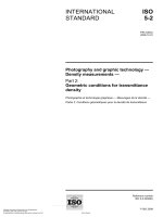
The current sensing coil of flexible type shall be set up as shown in Figure B.1 in order to guarantee
measuring accuracy.
In a portable type of welding current meter, all the above units, except the current sensing coil, are mounted in
one small box.
--`,,```,,,,````-`-`,,`,,`,`,,`---
Key
1
fixing
2
current sensing coil
3
resistance welding machine
4
integrator
5
data processing unit
6
display unit, recorder etc.
7
welding current meter
Figure B.1 — Typical set-up of the welding current meter with its coil
11
© ISO 2005 – All rights reserved
Copyright International Organization for Standardization
Reproduced by IHS under license with ISO
No reproduction or networking permitted without license from IHS
Not for Resale
ISO 17657-2:2005(E)
--`,,```,,,,````-`-`,,`,,`,`,,`---
ICS 25.160.10
Price based on 11 pages
© ISO 2005 – All rights reserved
Copyright International Organization for Standardization
Reproduced by IHS under license with ISO
No reproduction or networking permitted without license from IHS
Not for Resale