Tiêu chuẩn iso ts 19700 2007
Bạn đang xem bản rút gọn của tài liệu. Xem và tải ngay bản đầy đủ của tài liệu tại đây (452.02 KB, 42 trang )
TECHNICAL
SPECIFICATION
ISO/TS
19700
First edition
2007-03-15
Controlled equivalence ratio method for
the determination of hazardous
components of fire effluents
Méthode du rapport d'équivalence contrôlée pour la détermination des
substances dangereuses des effluents du feu
Reference number
ISO/TS 19700:2007(E)
--`,,```,,,,````-`-`,,`,,`,`,,`---
Copyright International Organization for Standardization
Provided by IHS under license with ISO
No reproduction or networking permitted without license from IHS
© ISO 2007
Not for Resale
ISO/TS 19700:2007(E)
PDF disclaimer
This PDF file may contain embedded typefaces. In accordance with Adobe's licensing policy, this file may be printed or viewed but
shall not be edited unless the typefaces which are embedded are licensed to and installed on the computer performing the editing. In
downloading this file, parties accept therein the responsibility of not infringing Adobe's licensing policy. The ISO Central Secretariat
accepts no liability in this area.
Adobe is a trademark of Adobe Systems Incorporated.
--`,,```,,,,````-`-`,,`,,`,`,,`---
Details of the software products used to create this PDF file can be found in the General Info relative to the file; the PDF-creation
parameters were optimized for printing. Every care has been taken to ensure that the file is suitable for use by ISO member bodies. In
the unlikely event that a problem relating to it is found, please inform the Central Secretariat at the address given below.
© ISO 2007
All rights reserved. Unless otherwise specified, no part of this publication may be reproduced or utilized in any form or by any means,
electronic or mechanical, including photocopying and microfilm, without permission in writing from either ISO at the address below or
ISO's member body in the country of the requester.
ISO copyright office
Case postale 56 • CH-1211 Geneva 20
Tel. + 41 22 749 01 11
Fax + 41 22 749 09 47
Web www.iso.org
Published in Switzerland
ii
Copyright International Organization for Standardization
Provided by IHS under license with ISO
No reproduction or networking permitted without license from IHS
© ISO 2007 – All rights reserved
Not for Resale
ISO/TS 19700:2007(E)
Contents
Page
Foreword............................................................................................................................................................. v
Introduction ....................................................................................................................................................... vi
Scope ..................................................................................................................................................... 1
2
Normative references ........................................................................................................................... 2
3
Terms and definitions........................................................................................................................... 2
4
Principle ................................................................................................................................................. 4
5
5.1
5.2
5.3
5.4
5.5
5.6
5.7
5.8
5.9
5.9.1
5.9.2
Apparatus .............................................................................................................................................. 5
General apparatus ................................................................................................................................ 5
Tube furnace ......................................................................................................................................... 5
Calibrated thermocouples ................................................................................................................... 7
Quartz furnace tube .............................................................................................................................. 7
Test-specimen boat .............................................................................................................................. 7
Test-specimen-boat drive mechanism ............................................................................................... 7
Mixing and measurement chamber..................................................................................................... 8
Analysis of gases.................................................................................................................................. 9
Determination of smoke ..................................................................................................................... 11
Aerosols and particulates .................................................................................................................. 11
Optical density of smoke ................................................................................................................... 11
6
Establishment of air supplies............................................................................................................ 11
7
7.1
7.2
7.3
Establishment of furnace temperature and setting of furnace temperature ................................ 12
General................................................................................................................................................. 12
Establishing furnace temperature profile to determine furnace suitability.................................. 12
Setting the temperature for an individual experimental-run condition......................................... 13
8
Test specimen preparation ................................................................................................................ 13
9
9.1
9.2
9.3
9.4
9.5
Selection of test decomposition conditions .................................................................................... 14
Selection of decomposition conditions for fire hazard analysis or fire-safety engineering....... 14
Stage 1b: oxidative pyrolysis from externally applied radiation ................................................... 14
Stage 2: well-ventilated flaming ........................................................................................................ 14
Stage 3a: small vitiated fires in closed or poorly ventilated compartments ................................ 15
Stage 3b: post-flashover fires in open compartments ................................................................... 15
10
10.1
10.2
10.2.1
10.2.2
10.2.3
10.3
Procedure ............................................................................................................................................ 15
Decomposition of the test sample .................................................................................................... 15
Sampling and analysis of fire effluent and measurement of smoke density ............................... 17
General................................................................................................................................................. 17
Sampling of fire effluent..................................................................................................................... 17
Determination of the mass of the specimen residue ...................................................................... 19
Validity of test run............................................................................................................................... 19
11
11.1
11.2
11.2.1
11.2.2
11.3
11.4
11.5
Calculations......................................................................................................................................... 19
General................................................................................................................................................. 19
Mass-charge concentration and mass-loss concentration ............................................................ 20
Mass-charge concentration ............................................................................................................... 20
Mass-loss concentration.................................................................................................................... 20
Smoke density..................................................................................................................................... 21
Yield...................................................................................................................................................... 21
Organic fraction .................................................................................................................................. 22
12
Test report ........................................................................................................................................... 23
--`,,```,,,,````-`-`,,`,,`,`,,`---
1
iii
© ISO 2007 – All rights reserved
Copyright International Organization for Standardization
Provided by IHS under license with ISO
No reproduction or networking permitted without license from IHS
Not for Resale
ISO/TS 19700:2007(E)
13
13.1
13.2
13.3
Repeatability and reproducibility ...................................................................................................... 24
Repeatability ........................................................................................................................................ 24
Reproducibility .................................................................................................................................... 25
Accuracy .............................................................................................................................................. 25
Annex A (informative) Guidance on choice of additional decomposition conditions............................... 26
Annex B (informative) Calculation of lethal toxic potency for combustion products according to
ISO 13344 using tube-furnace data ................................................................................................... 28
Annex C (informative) Application of data from the tube-furnace test to assessment of toxic
hazard in fires according to ISO 13571............................................................................................. 29
Annex D (informative) Guidance on application of data from the tube-furnace test to health and
safety assessments of combustion-products.................................................................................. 30
Annex E (informative) Guidance on application of data from the tube-furnace tests to assessment
of environmental hazards of combustion products from fires ...................................................... 31
Annex F (informative) Use of the tube-furnace method for bioassay purposes ........................................ 32
Bibliography ..................................................................................................................................................... 33
--`,,```,,,,````-`-`,,`,,`,`,,`---
iv
Copyright International
Organization for Standardization
Provided by IHS under license with ISO
No reproduction or networking permitted without license from IHS
© ISO 2007 – All rights reserved
Not for Resale
ISO/TS 19700:2007(E)
Foreword
ISO (the International Organization for Standardization) is a worldwide federation of national standards bodies
(ISO member bodies). The work of preparing International Standards is normally carried out through ISO
technical committees. Each member body interested in a subject for which a technical committee has been
established has the right to be represented on that committee. International organizations, governmental and
non-governmental, in liaison with ISO, also take part in the work. ISO collaborates closely with the
International Electrotechnical Commission (IEC) on all matters of electrotechnical standardization.
International Standards are drafted in accordance with the rules given in the ISO/IEC Directives, Part 2.
The main task of technical committees is to prepare International Standards. Draft International Standards
adopted by the technical committees are circulated to the member bodies for voting. Publication as an
International Standard requires approval by at least 75 % of the member bodies casting a vote.
—
an ISO Publicly Available Specification (ISO/PAS) represents an agreement between technical experts in
an ISO working group and is accepted for publication if it is approved by more than 50 % of the members
of the parent committee casting a vote;
—
an ISO Technical Specification (ISO/TS) represents an agreement between the members of a technical
committee and is accepted for publication if it is approved by 2/3 of the members of the committee casting
a vote.
An ISO/PAS or ISO/TS is reviewed after three years in order to decide whether it will be confirmed for a
further three years, revised to become an International Standard, or withdrawn. If the ISO/PAS or ISO/TS is
confirmed, it is reviewed again after a further three years, at which time it must either be transformed into an
International Standard or be withdrawn.
Attention is drawn to the possibility that some of the elements of this document may be the subject of patent
rights. ISO shall not be held responsible for identifying any or all such patent rights.
ISO/TS 19700 was prepared by Technical Committee ISO/TC 92, Fire safety, Subcommittee SC 3, Fire threat
to people and environment.
v
© ISO 2007 – All rights reserved
Copyright International Organization for Standardization
Provided by IHS under license with ISO
No reproduction or networking permitted without license from IHS
Not for Resale
--`,,```,,,,````-`-`,,`,,`,`,,`---
In other circumstances, particularly when there is an urgent market requirement for such documents, a
technical committee may decide to publish other types of normative document:
ISO/TS 19700:2007(E)
--`,,```,,,,````-`-`,,`,,`,`,,`---
Introduction
The framework for the long-term standardization of fire safety in support of performance-based design
(ISO/TC 92 SC 4) requires general engineering methods for specific performance aspects of fire safety, but is
applicable to all types of structural systems, products and processes. These are referred to in the document
as Level 2, Group B standards. One such aspect of fire safety is the yields of toxic products evolved in fires.
This Technical Specification has been developed to measure toxic product yields from materials and products
over a range of decomposition conditions in fires. The decomposition conditions are defined in terms of fuel/air
equivalence ratio, temperature and flaming behaviour.
The toxic potency of a fire effluent represents the combination of a number of factors, including the
concentrations of toxic products, gases, and smoke particles. The concentrations of toxic products in turn
depend upon a number of factors, one of which is the yield of each toxic product from the burning fuel. In
order to make a performance-based assessment of the toxic hazard in a fire, one required input is the yield of
toxic products under specified fire conditions.
For any specific material or product, the effluent yields in fires depend upon the thermal decomposition
conditions. The most important variables are whether the decomposition is non-flaming or flaming, and for
flaming decomposition the fuel/oxygen ratio. Based upon these variables, it is possible to classify fires into a
number of types, as detailed in ISO/TS 19706:2004, Table 1.
The use of this Technical Specification provides data on the range of toxic product yields likely to occur in
different types and stages of full-scale fires. More comprehensive data on the relationships between
decomposition conditions and product yields can be obtained by using a wider range of apparatus settings.
Guidance on the choice of additional decomposition conditions, the application of test data to ISO 13344 and
ISO 13571, to health and safety and environmental situations and the use of the tube-furnace method for
bioassay purposes is provided in the annexes.
This Technical Specification makes use of the same apparatus and a similar basic methodology as specified
in IEC 60695-7-50. The test method has been developed to fulfil the requirements of ISO 16312-1 and
ISO/TS 19706, for data on the yields of toxic products in fire effluents evolved under different fire conditions as
part of the data required for input to the toxic-hazard-assessment calculation methods described in ISO 13571.
The data may also be used as input for the toxic-potency calculation methods described in ISO 13344 and
ISO 13571.
vi
Copyright International Organization for Standardization
Provided by IHS under license with ISO
No reproduction or networking permitted without license from IHS
© ISO 2007 – All rights reserved
Not for Resale
TECHNICAL SPECIFICATION
ISO/TS 19700:2007(E)
Controlled equivalence ratio method for the determination of
hazardous components of fire effluents
1
Scope
It uses a moving test specimen and a tube furnace at different temperatures and air flow rates as the fire
model. The use of this apparatus is generally applicable to individual materials, to products that are layered
such that the layering will not result in a significant change in product yields with time in real fires, i.e. to
products where the upper surface does not provide major protection to the sub-layers.
This method has been designed as a TC 92 Level Group B performance-based engineering method to
provide data for input to hazard assessments and fire-safety engineering design calculations. The method can
be used to model a wide range of fire conditions by using different combinations of temperature, non-flaming
and flaming decomposition conditions and different fuel/oxygen ratios in the tube furnace. These include the
following types of fires, as detailed in ISO/TS 19706:2004, Table 1:
⎯
Stage 1: Non-flaming:
⎯
Stage 1b) Oxidative pyrolysis from externally applied radiation;
⎯
Stage 2: Well-ventilated flaming (representing a flaming developing fire) (see Note 1);
⎯
Stage 3: Less well-ventilated flaming (see Note 2):
⎯
Stage 3a) Small vitiated fires in closed or poorly ventilated compartments;
⎯
Stage 3b) Post-flashover fires in large or open compartments.
NOTE 1
Where the fire size is small in relation to the size of the compartment, the flames are below the base of the hot
layer and the fire size is fuel-controlled.
NOTE 2
Where the fire size may be large in relation to the size of the compartment, the flames are partly above the
base of the hot layer and the fire size is ventilation-controlled.
For each flaming fire type, the minimum conditions of test are specified in terms of the equivalence ratio φ as
follows:
Stage 2:
φ < 0,75;
Stages 3a) and 3b)
φ = 2 ± 0,2.
Guidance on the choice of additional decomposition conditions is given in Annex A.
The data on toxic product concentrations and yields obtained using this Technical Specification may be used
as part of the assessment of toxic potencies, in conjunction with toxic potency calculation methods in
ISO 13344, and as an input to the toxic hazard assessment from fires in conjunction with fire growth and
effluent dispersal modelling, and fractional effective dose (FED) calculation methods in ISO 13571.
1
© ISO 2007 – All rights reserved
Copyright International Organization for Standardization
Provided by IHS under license with ISO
No reproduction or networking permitted without license from IHS
Not for Resale
--`,,```,,,,````-`-`,,`,,`,`,,`---
This Technical Specification describes a tube-furnace method for the generation of fire effluent for the
identification and measurement of its constituent combustion products, in particular, the yields of toxic
products under a range of fire decomposition conditions.
ISO/TS 19700:2007(E)
Application of data from the tube-furnace test to the calculation of lethal toxic potency according to ISO 13344,
and to the assessment of toxic hazards in fires according to ISO 13571 is considered in Annex B and Annex C,
respectively.
Guidance on application of data from the tube-furnace test to health and safety assessments of combustion
products, and to the assessment of environmental hazards of combustion products from fires is given in
Annex D and Annex E, respectively. Guidance on the use of the tube-furnace method for bioassay purposes
is given in Annex F.
The test method described in this Technical Specification can be used solely to measure and describe the
properties of materials, products or systems in response to heat or flame under controlled laboratory
conditions. It is not suitable to be used by itself for describing or appraising the fire hazard of materials,
products or systems under actual fire conditions, or as the sole source on which regulations pertaining to
toxicity can be based.
2
Normative references
The following referenced documents are indispensable for the application of this document. For dated
references, only the edition cited applies. For undated references, the latest edition of the referenced
document (including any amendments) applies.
ISO 291:2005, Plastics — Standard atmospheres for conditioning and testing
ISO 554:1976, Standard atmospheres for conditioning and/or testing — Specifications
ISO 5660-2:2002, Reaction-to-fire tests — Heat release, smoke production and mass loss rate — Part 2:
Smoke production rate (dynamic measurement)
ISO 13344:2004, Estimation of the lethal toxic potency of fire effluents
ISO 13571, Life-threatening components of fire — Guidelines for the estimation of time available for escape
using fire data
ISO/IEC 13943, Fire safety — Vocabulary
ISO 19701:2005, Methods for sampling and analysis of fire effluents
ISO 19702:2006, Toxicity testing of fire effluents — Guidance for analysis of gases and vapours in fire
effluents using FTIR gas analysis
ISO/TS 19706:2004, Guidelines for assessing the fire threat to people
3
Terms and definitions
For the purposes of this document, the terms and definitions given in ISO 13344, ISO 13571, ISO 13943, and
the following apply.
3.1
combustible load
mass of the components of a test specimen capable of combustion in the furnace
NOTE
This usually includes all components of a specimen excluding inert fillers and other non-combustible
components, such as metal frames.
2
Copyright International Organization for Standardization
Provided by IHS under license with ISO
No reproduction or networking permitted without license from IHS
--`,,```,,,,````-`-`,,`,,`,`,,`---
© ISO 2007 – All rights reserved
Not for Resale
ISO/TS 19700:2007(E)
3.2
equivalence ratio
φ
fuel mass to oxygen mass ratio in the test divided by the stoichiometric fuel mass to oxygen mass ratio
NOTE
For the tube-furnace method, this is the mass loss rate of combustible effluent from the test specimen, in
milligrams per minute (mg⋅min−1), divided by the mass flow rate of oxygen in the primary air introduced into the furnace, in
milligrams per minute (mg⋅min−1), divided by the stoichiometric fuel mass to oxygen mass ratio for the material under test.
3.3
exposure dose
Ct
product of a gaseous toxicant or of a fire effluent which is available for inhalation, i.e. the integrated area
under the concentration(C)-time(t) curve
3.4
extinction coefficient
natural logarithm of the ratio of incident light intensity to transmitted light intensity, per unit light path length
3.5
fractional effective concentration
FEC
ratio of the concentration of an irritant to that expected to produce a given effect on an exposed subject of
average susceptibility
NOTE 1
As a concept, FEC may refer to any effect, including incapacitation, lethality or even other endpoints. Within
the context of this Technical Specification, FEC refers only to incapacitation.
NOTE 2
When not used with reference to a specific irritant, the term FEC represents the summation of FECs for all
irritants in a combustion atmosphere.
NOTE 3
When FEC = 1, the defined effect (incapacitation or death) is predicted to occur.
3.6
fractional effective dose
FED
ratio of the Ct product for an asphyxiant toxicant to that Ct product of the asphyxiant expected to produce a
given effect on an exposed subject of average susceptibility
NOTE 1
As a concept, FED may refer to any effect, including incapacitation, lethality or even other endpoints. Within
the context of this Technical Specification, FED refers only to incapacitation.
When FED = 1, the defined effect (incapacitation or death) is predicted to occur.
3.7
LC50
concentration of a toxic gas or fire effluent statistically calculated from concentration-response data to produce
lethality in 50 % of test animals within a specified exposure and post-exposure time
NOTE
The typical units are µL/L for a gaseous toxicant and gm−3 for fire effluent.
3.8
LCt50
product of LC50 and the exposure duration over which it was determined
NOTE
The typical units are µLL−1min for a gaseous toxicant and gm−3min for fire effluent. This constitutes a measure
of lethal toxic potency.
3
© ISO 2007 – All rights reserved
Copyright International Organization for Standardization
Provided by IHS under license with ISO
No reproduction or networking permitted without license from IHS
Not for Resale
--`,,```,,,,````-`-`,,`,,`,`,,`---
NOTE 2
ISO/TS 19700:2007(E)
3.9
mass-charge concentration
concentration of fire effluents from a material defined in terms of the mass of material exposed to burning
conditions (mass charge) and the volume into which the effluent is dispersed, expressed in g⋅m−3
3.10
mass loss concentration
concentration of fire effluents from a material defined in terms of the mass of material decomposed (mass
loss) and the volume into which the effluent is dispersed, expressed in g⋅m−3
3.11
mass loss exposure dose
mass loss concentration multiplied by the exposure time, expressed in g⋅m−3min
[BS 7899-2:1999, definition 2.22]
3.12
smoke extinction area
SEA
ratio of the smoke extinction coefficient, in reciprocal metres (m−1) to the mass loss concentration of the test
specimen, expressed as grams per cubic metre (g⋅m−3) having units of metres squared per gram (m2⋅g−1)
3.13
smoke obscuration
reduction, usually expressed as a percentage, in the intensity of light due to its passage through smoke
3.14
smoke production
integral of the smoke production rate over the steady-state burn period being considered
3.15
volume yield
volume of an effluent component at 20 °C and 101,325 kPa divided by the mass loss of the test specimen
associated with the production of that volume of the effluent component
3.16
yield
mass of an effluent component divided by the mass loss of the test specimen associated with the production
of that mass of the effluent component
4
Principle
Since the yields of products in fires depend upon the decomposition conditions (references [1] to [5]), it is
possible to examine the relationships between product yield and a range of variables affecting the
decomposition conditions using this apparatus and the methodology described. The specified test conditions
represent a minimum set designed to obtain data for oxidative pyrolysis under non-flaming conditions, for wellventilated flaming conditions at an equivalence ratio of less than 0,75, and for vitiated flaming conditions at an
equivalence ratio of more than 2. The test is designed to replicate real fire conditions, and it is essential that
proper observations are made to ensure that those conditions are being met.
Samples of a material or product are combusted under steady-state conditions in one or more of four
environments whose temperature and equivalence ratio are representative of a particular stage of a fire. The
four types of fire to be represented are: oxidative pyrolysis, well-ventilated flaming developing fires, small
flaming vitiated fires, and post-flashover vitiated fires, as defined in ISO/TS 19706.
A test specimen in granular or rod form, or a product, is placed in a quartz boat, and introduced at a constant
rate into a furnace tube through the hot zone of a fixed tubular furnace. A stream of primary air is passed
through the furnace tube and over the test specimen at constant flow rate, to support combustion. The fire
--`,,```,,,,````-`-`,,`,,`,`,,`---
4
Copyright International
Organization for Standardization
Provided by IHS under license with ISO
No reproduction or networking permitted without license from IHS
© ISO 2007 – All rights reserved
Not for Resale
ISO/TS 19700:2007(E)
effluent is expelled from the quartz furnace tube into a mixing and measuring chamber, where it is diluted with
secondary air to a nominal total air flow rate of (50 ± 1) l⋅min−1 through the chamber and then exhausted to
waste.
In the oxidative pyrolysis mode, the furnace temperature is set below the auto-ignition temperature. The three
flaming modes are accomplished by using vapour temperatures above typical auto-ignition temperatures. For
flaming decomposition conditions, different fuel-to-oxygen ratios, and hence different equivalence ratios, are
obtained when different, constant primary air flows are used in relation to the constant rate of introduction of
the fuel. To achieve the required gasification rates, materials may be combusted under different conditions
from each other.
--`,,```,,,,````-`-`,,`,,`,`,,`---
The secondary, dilution air is added to generate a greater sample flow and cooler effluent which permits a
large number of gas and smoke sampling procedures to be used without the need for a large number of
replicate tests.
The requirement in each test run is to obtain stable, steady-state decomposition conditions for at least 5 min
during which the concentrations of effluent gases and particles can be measured. The time taken for steadystate conditions to be established varies, depending upon the nature of the test specimen and the test
conditions.
The concentrations of carbon dioxide and oxygen are recorded to establish the steady-state period and
samples of the effluent mixture are taken from the chamber during the steady-state period for analysis. Smoke
obscuration and smoke yield are calculated from measurement of the attenuation of a light beam by the
combustion effluent stream in the mixing chamber. A sample of smoke is drawn through a filter, and the mass
of particles is determined.
5
5.1
Apparatus
General apparatus
The apparatus consists of a tube furnace and a quartz tube which passes through the furnace and into a
mixing and measurement chamber. A drive mechanism pushes the specimen boat into the furnace tube at a
preset, controlled rate. A constant, predetermined stream of primary air is provided at the furnace-tube entry
and a preset, secondary supply into the mixing and measurement chamber. Gas samples are taken from the
mixing and measurement chamber. A light/photo cell system is used to determine smoke density across the
mixing and measurement chamber.
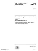
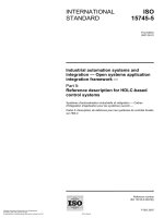
The arrangement of the apparatus is shown in Figure 1. Unless otherwise stated, all tolerances are ± 5 mm.
5.2
Tube furnace
The tube furnace shall have a heating zone length of 500 mm to 800 mm and an inside diameter of 50 mm to
65 mm. The furnace shall be equipped with an adjustable electric heating system capable of maintaining the
furnace temperature to within ± 2 % of the set temperature. The heating element should preferably be rated at
1 300 °C (see Note 1).
With the peak furnace temperature set at (650 ± 10) °C, the temperature shall not decrease by more than
100 °C over a length of at least ± 125 mm from the point of peak temperature measurement. The method
used to determine this temperature profile is given in 7.2 (see Note 2).
NOTE 1
The furnace is similar to that used in IEC 60754-2.
NOTE 2
This will also reduce the likelihood of a hot spot in the furnace, to which the pyrolysis rate will be sensitive.
5
© ISO 2007 – All rights reserved
Copyright International Organization for Standardization
Provided by IHS under license with ISO
No reproduction or networking permitted without license from IHS
Not for Resale
ISO/TS 19700:2007(E)
Key
1
2
tube furnace
quartz furnace tube
8
9
ports for sampling lines
smoke-particle filter
3
4
test-specimen boat
test-specimen boat drive mechanism
10 tube containing light source
11 tube containing photodetector
5
6
mixing and measurement chamber
primary air inlet
12 gas bubblers
13 pump with flow meter
7
secondary air inlet
a) General arrangement of apparatus
Dimensions in millimetres
Key
1
secondary air inlet 45° to vertical
2
3
tube furnace
furnace tube
4
sample boat 800
b) Critical dimensions of assembly
Figure 1 — Tube-furnace decomposition and sampling apparatus
6
--`,,```,,,,````-`-`,,`,,`,`,,`---
Copyright International Organization for Standardization
Provided by IHS under license with ISO
No reproduction or networking permitted without license from IHS
© ISO 2007 – All rights reserved
Not for Resale
--`,,```,,,,````-`-`,,`,,`,`,,`---
ISO/TS 19700:2007(E)
5.3
Calibrated thermocouples
Calibrated stainless-steel sheathed thermocouples, 1,5 ± 0,1 mm in diameter, shall be used for measuring the
temperature in the furnace tube, the temperature in the mixing and measurement chamber and for calibrating
the furnace. Three thermocouples are required.
5.4
Quartz furnace tube
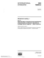
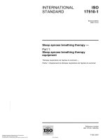
The quartz furnace tube, as shown in Figure 2, is made of clear heat-resistant quartz, resistant to the effects
of fire effluent. The tube is 1 600 mm long, and has an external, approximately concentric diameter of
(47,5 ± 1) mm and a wall thickness of (2 ± 0,5) mm. The outside diameter shall permit a smooth fit within the
tube furnace (5.2) and allow expansion at operating temperatures.
The input end of the furnace tube shall have a closure with openings in it to allow the primary air inlet and the
specimen boat drive to pass through (see Note 1).
The downstream end of the furnace tube shall pass through a heat-resisting sealed gland and shall protrude
55 ± 5 mm into the mixing and measurement chamber (5.7). (see Note 2).
The distance between the mixing and measurement chamber and the exit of the furnace shall be 30 ± 5 mm.
NOTE 1
A PTFE gland seal has been found to be suitable.
NOTE 2
A gland made from glass wool inside a brass collar has been found to be suitable.
5.5
Test-specimen boat
The test-specimen boat, as shown in Figure 2, is made from quartz glass (see Note 1), of diameter
(41 ± 2) mm, with a length of 800 mm and a wall thickness of (2 ± 0,5) mm (see Notes 2 and 3). The boat
should be cleaned after each test (see Note 4).
NOTE 1
A convenient method for making a suitable test-specimen boat for a 47,5 mm diameter furnace tube is to use
quartz tubing with a nominal diameter less than that of the furnace tube (nominal 41 mm). This can then be sliced in half to
provide a semi-circular cross-section, nominally of 41 mm width, 18 mm depth and 800 mm length.
NOTE 2
A test-specimen-boat diameter (41 mm) of just less than the furnace-tube internal diameter (47 mm) provides
the maximum sample capacity.
NOTE 3
A boat length of 800 mm has been found suitable for testing most materials. Where materials take a long time
to reach steady-state burning, or where a steady-state period of longer that 5 min is required, longer boats may be used.
NOTE 4
A convenient method of cleaning both the boat and tube is to remove obvious residues mechanically, then fire
at 1 000 °C, followed by washing in water to remove any inorganic residues.
5.6
Test-specimen-boat drive mechanism
The test-specimen boat is connected to a hooked drive bar, which passes through a gland seal (see 5.4) at
the upstream end of the furnace tube, and connects to a drive mechanism. The drive mechanism advances
the sample boat at a typical rate of (40 ± 1) mm⋅min−1. The drive mechanism shall allow different speeds to be
used, because the actual rate is dependent upon the flame spread characteristics of the sample (see Note).
The mechanism shall enable the specimen boat to be rapidly retracted into the upstream, external part of the
furnace tube at the end of the test burn. This may be achieved manually after detaching the push rod from the
drive mechanism.
NOTE
A drive advance rate of 40 mm⋅min−1 has been found suitable for most materials under most decomposition
conditions. For some fast-burning or low-density materials, it has been found necessary to use advance rates of up to
60 mm⋅min−1.
7
© ISO 2007 – All rights reserved
Copyright International Organization for Standardization
Provided by IHS under license with ISO
No reproduction or networking permitted without license from IHS
Not for Resale
ISO/TS 19700:2007(E)
Dimensions in millimetres
a) Quartz furnace tube
b) Test-specimen boat
Figure 2 — Dimensions of a suitable quartz furnace tube and test-specimen boat
5.7
Mixing and measurement chamber
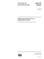
This shall consist of an approximately cubic box with a side length of 30 to 32 cm (see Figure 3) although the
exact dimensions are not critical. The box should accommodate the necessary sampling and measurement
points (gas sampling probes to bubblers, etc., particulate filters and smoke meter) (see Note 1). The front of
the chamber has a door providing a seal when shut. The walls of the box are made of PMMA, polycarbonate,
polyethylene or other suitable material, except for the back wall of the chamber and the rear portion of the roof
which are made of stainless steel, so as to be resistant to heat and any flames emanating from the end of the
furnace tube (see Notes 2 and 3).
The roof of the chamber is fitted with a safety blow-out panel 75 mm in diameter, made of aluminium foil
approximately 0,04 mm thick (see Note 3).
Sampling ports and probes are provided in the mixing chamber for taking samples of the test atmosphere. The
open end of the sampling probe shall be (30 ± 5) mm from the wall of the mixing and measurement chamber
(see Note 4).
A port approximately 35 mm in diameter is provided at the base of the rear face of the chamber for the test
atmosphere to be exhausted to waste.
Ports are provided in the mixing and measurement chamber for the insertion of a light source and detector for
the measurement of smoke density (see Note 5). Measurement points are located away from the rising plume
and the chamber walls; these may be sited in any convenient location. Suitable methods for the prevention of
the deposition of particles on the surfaces of both the light source and detector shall be used (see Note 6).
--`,,```,,,,````-`-`,,`,,`,`,,`---
8
Copyright International Organization for Standardization
Provided by IHS under license with ISO
No reproduction or networking permitted without license from IHS
© ISO 2007 – All rights reserved
Not for Resale
ISO/TS 19700:2007(E)
A thermocouple (5.3), extending approximately 50 mm into the mixing and measurement chamber, is located
as shown in Figure 3, for monitoring of the temperature in the chamber during the tests.
NOTE 1
The volume of the mixing and measurement chamber needs to be large enough to accommodate the
sampling points but smaller than the total volume of air flowing through the box in 1 min.
NOTE 2
A suitable chamber can be made from a commercially available desiccator cabinet with nominal dimensions of
310 mm × 310 mm × 340 mm (see Figure 3). This would have an internal volume of 33 l compared to the air flow volume
of 50 l in 1 min. The furnace-tube entry wall of the chamber cabinet should be covered by a stainless-steel plate fitted to
the inner surface; the top of the plate extending 140 mm across the chamber roof to provide heat protection for the plastic
surfaces.
NOTE 3
This is important for safety reasons.
NOTE 4
The sampling points are positioned away from the furnace-tube exit plume and chamber walls but can be sited
in any convenient location. Suitable locations are shown in Figure 3.
A suitable smoke-measurement path length has been found to be approximately 300 mm.
--`,,```,,,,````-`-`,,`,,`,`,,`---
NOTE 5
NOTE 6
A suitable method has been to mount the photodectector and lamp vertically as in Figure 3 and pass part of
the chamber diluent air into tubes containing the light source and detector at a rate of 500 ml⋅min−1. A further modification
to reduce particle deposition is to mount the photodetector and lamp horizontally.
5.8
Analysis of gases
This Technical Specification requires the determination of certain combustion gases. The means of gas
sampling and analysis shall be those given in ISO 19701 and ISO 19702.
Carbon dioxide and oxygen concentrations shall be sampled and determined continuously throughout the test.
These data are used to identify and monitor the steady-state burn period and also to quantify the gas yields.
The concentration of carbon monoxide shall also be determined continuously to quantify the gas yield.
The oxygen meter shall be capable of an accuracy of 0,01 %. Details of a suitable oxygen meter and sampling
system are given in ISO 5660-1.
The following other gases shall be determined during the steady-state burn period (see Note):
⎯
organic irritants including formaldehyde and acrolein;
⎯
total organic fraction;
⎯
acid gases, including hydrogen cyanide, hydrogen chloride, hydrogen bromide, hydrogen fluoride,
nitrogen oxides and sulfur dioxide if the presence of the relevant elements is suspected.
Other gases may need to be determined, if suspected from knowledge of the compound (see Note).
NOTE
The above list is not to be considered inclusive. A compound may be excluded from the effluent analysis if one
or more of the elements in that compound is determined not to be present in the test specimen, or if citable evidence
shows the compound is not likely to be present in a toxicologically significant quantity. For more sophisticated analyses,
other individual organic irritants (e.g. other organo-aldehydes, isocyanates, organo-nitriles, etc.) may be measured directly.
The selection of organics to be monitored should be justified in the report and based on citable scientific literature on
combustion-product analyses or elemental composition of the material tested.
9
© ISO 2007 – All rights reserved
Copyright International Organization for Standardization
Provided by IHS under license with ISO
No reproduction or networking permitted without license from IHS
Not for Resale
ISO/TS 19700:2007(E)
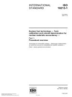
Dimensions in millimetres
Key
1
door
8
smoke particle filter
2
tube containing photodetector
9
ports for sampling lines
3
tube containing light source
10
secondary air inlet
4
purge tubes for photodetector and light source
11
port for thermocouple
5
quartz furnace tube
12
6
stainless-steel plate
port for tube to sample atmosphere in furnace tube for
measurement of oxygen concentration
7
safety blow-out panel
13
exhaust port
A
top
B
C
front
back
Figure 3 — Dimensions of mixing and measurement chamber
--`,,```,,,,````-`-`,,`,,`,`,,`---
10 Organization for Standardization
Copyright International
Provided by IHS under license with ISO
No reproduction or networking permitted without license from IHS
© ISO 2007 – All rights reserved
Not for Resale
ISO/TS 19700:2007(E)
5.9
Determination of smoke
5.9.1
Aerosols and particulates
These are continuously sampled in the mixing and measurement chamber through a particle filter at an
appropriate flow.
NOTE
A glass microfibre filter 0,26 mm thick with a 1,6 µm particle retention characteristic and a diameter of 37 mm
has been found to be suitable.
5.9.2
Optical density of smoke
The smoke optical density is calculated from measurement of the attenuation of a laser light beam by the
combustion-product stream in the mixing chamber. Smoke obscuration is recorded continuously for the
steady-state burn period of the test.
A suitable smoke-determining system is given in ISO 5660-2 (see Note).
Two glass neutral-density dispersion filters, accurately calibrated at the laser wavelength of 632,8 nm, are
required to calibrate the smoke-determining system. The filters used shall not be of the coated type, because
these filters can give rise to interference effects with laser light and can deteriorate with time. The filters shall
have nominal optical densities (D) of 0,3 and 0,8. Corresponding values of extinction coefficient, k, are
obtained from the formula:
k = (2,303D)L−1
where L is the distance between the entrances of the light emitter/detector system.
NOTE
Experimental work has been performed with ISO 5660-2 with systems using a white light source with
collimating optics. Such systems have been shown to yield generally similar results, but not under all conditions.
Theoretical predictions have been verified experimentally. White light systems may be used if they are shown to have an
equivalent accuracy.
6
Establishment of air supplies
6.1 The primary and secondary air supplies to the apparatus shall be clean and free from excessive
moisture that could interfere with burning characteristics or combustion-product analysis. The water content
and/or the relative humidity of the air shall be reported (see Note 1).
6.2 Both the primary and secondary air flows are delivered at a constant, predetermined rate, positive
pressure and monitored using in-line flow meters. Air flow rates must be calibrated at the point of entry to the
furnace tube and chamber (see Note 2).
6.3
The primary air shall be introduced through the closure at the input end of the furnace tube.
6.4 The secondary air shall be introduced into the mixing box using piping of internal diameter 3 mm to
4 mm, passing through the wall of the mixing and measurement chamber and ending (70 ± 5) mm above and
in line with the end of the furnace tube and pointing upwards at an angle of approximately 45°. The secondary
air supply intercepts the rising plume to facilitate the efficient mixing of the test atmosphere (see Note 3).
NOTE 1
suitable.
Oil free compressed air passed through a carbon trap and silica gel, or bottled air, has been found to be
NOTE 2
The flow meters shall be calibrated using a bubble meter. A correction for back pressure at the in-line flow
meters may be necessary.
NOTE 3
This system will give good mixing of the furnace effluent and the secondary air, and removes the need for a
mechanical stirring device.
© ISO 2007 – All rights reserved
Copyright International Organization for Standardization
Provided by IHS under license with ISO
No reproduction or networking permitted without license from IHS
--`,,```,,,,````-`-`,,`,,`,`,,`---
Not for Resale
11
ISO/TS 19700:2007(E)
7
Establishment of furnace temperature and setting of furnace temperature
7.1
General
7.2
--`,,```,,,,````-`-`,,`,,`,`,,`---
There are two stages included in the temperature standardization. The first stage is to establish that the
temperature profile (change of temperature with distance through the furnace tube) of the particular furnace to
be used is suitable; the second stage is to determine the temperature setting needed for the particular
experimental-run condition to be carried out.
Establishing furnace temperature profile to determine furnace suitability
Set up the furnace, with an empty quartz furnace tube in place, under static conditions (i.e. with no air flow
through the furnace tube). Close the furnace tube at one end with a bung to prevent air flow through the
furnace and set the furnace temperature controller at 680 °C. Introduce the calibrated thermocouple (5.3) into
the quartz furnace tube, with the tip of the thermocouple in air within a 10 mm radius of the centre of the
quartz furnace tube (see Note).
Allow the furnace to reach equilibrium. Then measure the temperature profile along the furnace tube by taking
measurements at intervals of no greater than 25 mm to find the point of maximum temperature. This should
be near the centre of the furnace and the maximum temperature should be (650 ± 10) °C. If the maximum
temperature is outside this range, adjust the furnace temperature controller to bring the maximum temperature
into this range.
From the results obtained, determine the location of the point of maximum temperature and record the
temperature at that point. Make further measurements also at intervals of no greater than 25 mm on each side
of the location of the point of maximum temperature, until points are reached at which the temperature
decrease relative to the maximum temperature exceeds 100 °C. For the furnace to be acceptable, these
points should lie between 125 mm and 250 mm from the location of the point of maximum temperature.
NOTE
A suitable support for the thermocouple is shown in Figure 4.
Key
1
position of thermocouple supports inside furnace tube to position thermocouple in centre of tube
Figure 4 — Wire thermocouple support rings allowing thermocouple to move along
in required position
12
Copyright International Organization for Standardization
Provided by IHS under license with ISO
No reproduction or networking permitted without license from IHS
© ISO 2007 – All rights reserved
Not for Resale
ISO/TS 19700:2007(E)
7.3
Setting the temperature for an individual experimental-run condition
Once it has been determined that the furnace temperature profile is suitable, the only temperature setting
necessary for an experimental run is the maximum temperature under air flow conditions (Trun ). In order to set
the maximum temperature for an experimental run, set up the furnace with the quartz furnace tube in place
and set up the appropriate primary air flow through the furnace tube. Introduce the calibrated thermocouple
(5.3) into the quartz furnace tube as described in 8.2 and allow it to reach equilibrium. Once a primary air flow
has been established, the point of maximum temperature moves downstream relative to its location under
static conditions. In order to compensate for this shift, position the thermocouple tip (75 ± 10) mm downstream
of the point of maximum temperature established under static conditions (see 8.2). This position introduces a
minimum error for flow rates of up to 20 l⋅min−1. Then adjust the furnace temperature controller until a
temperature within ± 5 °C of the desired value for Trun is obtained.
NOTE
It is necessary to specify the furnace conditions for the test. The conditions given above are based on
experimental work using typical commercially available furnaces 500 to 600 mm long. If the furnace hot zone is too short
then the test specimen and decomposition products might not be heated for a sufficient time. Hot zones longer than
600 mm are less likely to present problems, but it is possible that the longer period for which the test specimen and
decomposition products are heated could result in small differences in the combustion-product yields. The above has been
found to be satisfactory in use.
8
Test specimen preparation
8.1 The test specimen preferably should be in the form of a rod of uniform cross-sectional area. Details of
the test specimen and its form shall be included in the test report (as described in 12.2) (see Note).
NOTE
Test specimens may be in various forms depending upon the nature of the material. It has been shown that
the form of the sample itself can have an effect on the results. The use of this apparatus is generally limited to
homogeneous materials, and layered materials where the outer layers do not prevent involvement of the inner layers
during the course of a fire.
8.2 The test specimen shall be uniformly distributed along the length of the sample boat, so that a constant
flow of decomposition products is produced as the test specimen passes through the furnace. The specimen
combustible loading should be approximately 25 mg⋅mm−1 (20 g spread over 800 mm). To give this loading, a
specimen rod with a density of 1 g⋅ml−1 would have a cross-sectional area of 25 mm2 (see next paragraph).
Specimen preparation may also have a minor effect on test results. This may occur with, for example, nonmelting materials, cables, layered materials, etc., and it is important that details of the test specimen shall be
reported. The results for non-melting, granular materials may be affected by the size of the granules.
In the case of materials that are subject to rapid flame spread or that might distort or shrink on introduction
into the furnace, the test specimens may be divided into short lengths. These specimen forms are acceptable,
providing the material is uniformly distributed along the length of the boat such that the specimen loading per
unit length is known and so that the rate of decomposition can be determined.
Materials having densities below approximately 0,05 g⋅ml−1 can be so large that they interfere with the air flow
through the furnace tube at a specimen loading of 25 mg⋅mm−1. To overcome this problem, it is acceptable to
reduce the specimen loading and increase the test-specimen-boat advance rate to compensate (see 5.6).
For materials which contain an inert matrix or fillers which do not form part of the combustible mass, the mass
loading of material in the test specimen should be increased to compensate.
8.3 Before the test, specimens shall be conditioned to constant mass at a temperature of (23 ± 2) °C, and a
relative humidity of (50 ± 5) %, in accordance with ISO 554.
Constant mass is considered to be reached when two successive weighing operations, carried out at an
interval of 24 h, do not differ by more than 0,1 % of the mass of the test piece or 0,1 g, whichever is the
greater (see next paragraph).
Materials such as polyamides, which require more than 1 week in a conditioning atmosphere to reach
equilibrium, may be tested after conditioning in accordance with ISO 291. This period shall be not less than
1 week, and shall be described in the test report.
--`,,```,,,,````-`-`,,`,,`,`,,`---
13
© ISO for
2007
– All rights reserved
Copyright International Organization
Standardization
Provided by IHS under license with ISO
No reproduction or networking permitted without license from IHS
Not for Resale
ISO/TS 19700:2007(E)
9
Selection of test decomposition conditions
9.1
Selection of decomposition conditions for fire hazard analysis or fire-safety engineering
Test specimens shall be decomposed or combusted under one or all of the conditions set forth below.
ISO/TS 19706:2004, Table 1 defines the various fire stages, 1b, 2, 3a and 3b. For stage 2, the procedure
provides an equivalence ratio φ of < 0,75. For stages 3a and 3b, the procedure provides a φ of > 2,0 ± 0,2.
A test run is only valid if the selected steady-state conditions (see 10.1) are maintained for a period of at least
5 min during the test. If ignition occurs during a non-flaming run, or fails to occur during a flaming run, then the
furnace temperature shall be raised or lowered in 25 °C steps until the required behaviour is obtained. A new
test run shall then be carried out with a fresh test specimen. For flaming behaviour, it is also necessary to
ensure that the primary air flow rates are correct, as specified in 9.3, 9.4 and 9.5.
9.2
Stage 1b: oxidative pyrolysis from externally applied radiation
9.2.1
Place a test-pecimen combustible loading of 25 mg⋅mm−1 in the specimen boat.
9.2.2
Set the furnace temperature to obtain a Trun of 350 °C.
9.2.3
Set the primary air flow to 2 l⋅min−1.
9.2.4 If flaming decomposition occurs during the run, repeat at temperatures progressively 25 °C lower until
continuous, non-flaming decomposition is obtained throughout the steady-state period.
9.3
Stage 2: well-ventilated flaming
9.3.1
Place a test-specimen combustible loading of 25 mg⋅mm−1 in the specimen boat.
Set the furnace temperature to obtain a Trun of 650 °C. Set the primary air flow rate to 10 l⋅min−1 and
the secondary air flow rate to 40 l⋅min−1.
9.3.2
9.3.3
Complete a test run as described in the procedure in 10.1.
9.3.4 From the average percent oxygen concentration in the mixing and measurement chamber (MO2)
calculated to 2 decimal places; calculate the oxygen depletion (DO2) as follows:
DO2 = 20,95 − MO2
If DO2 < 3,14 % and > 1,8 % then φ < 0,75 and the run meets the criteria of this Technical Specification for
well-ventilated flaming.
If DO2 > 3,14 % then φ > 0,75 and the run is unacceptable. Repeat with a primary air flow rate of 15 l⋅min−1.
Under these conditions, φ < 0,75 and the run meets the criteria of this Technical Specification for wellventilated flaming.
If DO2 > 1,5 % and < 1,8 % then φ < 0,75 but the combustible fuel content is too low to obtain reliable data.
Repeat the run with a specimen mass loading of × 1,5.
14
Copyright International Organization for Standardization
Provided by IHS under license with ISO
No reproduction or networking permitted without license from IHS
© ISO 2007 – All rights reserved
Not for Resale
--`,,```,,,,````-`-`,,`,,`,`,,`---
Preliminary test runs, according to the procedures of Clause 10, will need to be carried out to determine the
test conditions for materials of unknown decomposition behaviour. It is essential to measure carbon dioxide
and oxygen concentrations, mass loss and possibly smoke, to establish the conditions for steady-state
decomposition according to the defined fire types. Guidance on the selection of additional decomposition
conditions is presented in Annex A.