TRUYỀN SỐ LIỆU VÀ MẠNG Solution manual for data communications and networking by behrouz forouzan cuuduongthancong com
Bạn đang xem bản rút gọn của tài liệu. Xem và tải ngay bản đầy đủ của tài liệu tại đây (3.3 MB, 170 trang )
CHAPTER 1
Introduction
Solutions to Review Questions and Exercises
Review Questions
1. The five components of a data communication system are the sender, receiver,
transmission medium, message, and protocol.
2. The advantages of distributed processing are security, access to distributed databases, collaborative processing, and faster problem solving.
3. The three criteria are performance, reliability, and security.
4. Advantages of a multipoint over a point-to-point configuration (type of connection) include ease of installation and low cost.
5. Line configurations (or types of connections) are point-to-point and multipoint.
6. We can divide line configuration in two broad categories:
a. Point-to-point: mesh, star, and ring.
b. Multipoint: bus
7. In half-duplex transmission, only one entity can send at a time; in a full-duplex
transmission, both entities can send at the same time.
8. We give an advantage for each of four network topologies:
a. Mesh: secure
b. Bus: easy installation
c. Star: robust
d. Ring: easy fault isolation
9. The number of cables for each type of network is:
a. Mesh: n (n – 1) / 2
b. Star: n
c. Ring: n – 1
d. Bus: one backbone and n drop lines
10. The general factors are size, distances (covered by the network), structure, and
ownership.
1
CuuDuongThanCong.com
/>
2
11. An internet is an interconnection of networks. The Internet is the name of a specific worldwide network
12. A protocol defines what is communicated, in what way and when. This provides
accurate and timely transfer of information between different devices on a network.
13. Standards are needed to create and maintain an open and competitive market for
manufacturers, to coordinate protocol rules, and thus guarantee compatibility of
data communication technologies.
Exercises
14. Unicode uses 32 bits to represent a symbol or a character. We can define 232 different symbols or characters.
15. With 16 bits, we can represent up to 216 different colors.
16.
a. Cable links: n (n – 1) / 2 = (6 × 5) / 2 = 15
b. Number of ports: (n – 1) = 5 ports needed per device
17.
a. Mesh topology: If one connection fails, the other connections will still be working.
b. Star topology: The other devices will still be able to send data through the hub;
there will be no access to the device which has the failed connection to the hub.
c. Bus Topology: All transmission stops if the failure is in the bus. If the drop-line
fails, only the corresponding device cannot operate.
d. Ring Topology: The failed connection may disable the whole network unless it
is a dual ring or there is a by-pass mechanism.
18. This is a LAN. The Ethernet hub creates a LAN as we will see in Chapter 13.
19. Theoretically, in a ring topology, unplugging one station, interrupts the ring. However, most ring networks use a mechanism that bypasses the station; the ring can
continue its operation.
20. In a bus topology, no station is in the path of the signal. Unplugging a station has
no effect on the operation of the rest of the network.
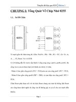
21. See Figure 1.1
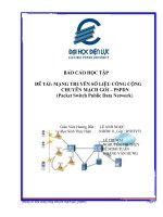
22. See Figure 1.2.
23.
a. E-mail is not an interactive application. Even if it is delivered immediately, it
may stay in the mail-box of the receiver for a while. It is not sensitive to delay.
b. We normally do not expect a file to be copied immediately. It is not very sensitive to delay.
c. Surfing the Internet is the an application very sensitive to delay. We except to
get access to the site we are searching.
24. In this case, the communication is only between a caller and the callee. A dedicated line is established between them. The connection is point-to-point.
CuuDuongThanCong.com
/>
3
Figure 1.1 Solution to Exercise 21
Hub
Station
Repeater
Station
Station
Station
Station
Repeat er
Station
Repeat er
Station
Station
Station
Figure 1.2 Solution to Exercise 22
Station
Station
Repeater
Repeater
Station
Station
25. The telephone network was originally designed for voice communication; the
Internet was originally designed for data communication. The two networks are
similar in the fact that both are made of interconnections of small networks. The
telephone network, as we will see in future chapters, is mostly a circuit-switched
network; the Internet is mostly a packet-switched network.
CuuDuongThanCong.com
/>
4
CuuDuongThanCong.com
/>
Sol-02.fm Page 1 Saturday, January 21, 2006 10:27 AM
CHAPTER 2
Network Models
Solutions to Review Questions and Exercises
Review Questions
1. The Internet model, as discussed in this chapter, include physical, data link, network, transport, and application layers.
2. The network support layers are the physical, data link, and network layers.
3. The application layer supports the user.
4. The transport layer is responsible for process-to-process delivery of the entire
message, whereas the network layer oversees host-to-host delivery of individual
packets.
5. Peer-to-peer processes are processes on two or more devices communicating at a
same layer
6. Each layer calls upon the services of the layer just below it using interfaces
between each pair of adjacent layers.
7. Headers and trailers are control data added at the beginning and the end of each
data unit at each layer of the sender and removed at the corresponding layers of the
receiver. They provide source and destination addresses, synchronization points,
information for error detection, etc.
8. The physical layer is responsible for transmitting a bit stream over a physical
medium. It is concerned with
a. physical characteristics of the media
b. representation of bits
c. type of encoding
d. synchronization of bits
e. transmission rate and mode
f. the way devices are connected with each other and to the links
9. The data link layer is responsible for
a. framing data bits
b. providing the physical addresses of the sender/receiver
c. data rate control
1
CuuDuongThanCong.com
/>
Sol-02.fm Page 2 Saturday, January 21, 2006 10:27 AM
2
10.
11.
12.
13.
14.
d. detection and correction of damaged and lost frames
The network layer is concerned with delivery of a packet across multiple networks; therefore its responsibilities include
a. providing host-to-host addressing
b. routing
The transport layer oversees the process-to-process delivery of the entire message.
It is responsible for
a. dividing the message into manageable segments
b. reassembling it at the destination
c. flow and error control
The physical address is the local address of a node; it is used by the data link layer
to deliver data from one node to another within the same network. The logical
address defines the sender and receiver at the network layer and is used to deliver
messages across multiple networks. The port address (service-point) identifies the
application process on the station.
The application layer services include file transfer, remote access, shared database management, and mail services.
The application, presentation, and session layers of the OSI model are represented
by the application layer in the Internet model. The lowest four layers of OSI correspond to the Internet model layers.
Exercises
15. The International Standards Organization, or the International Organization of
Standards, (ISO) is a multinational body dedicated to worldwide agreement on
international standards. An ISO standard that covers all aspects of network communications is the Open Systems Interconnection (OSI) model.
16.
a. Route determination: network layer
b. Flow control: data link and transport layers
c. Interface to transmission media: physical layer
d. Access for the end user: application layer
17.
a. Reliable process-to-process delivery: transport layer
b. Route selection: network layer
c. Defining frames: data link layer
d. Providing user services: application layer
e. Transmission of bits across the medium: physical layer
18.
a. Communication with user’s application program: application layer
b. Error correction and retransmission: data link and transport layers
c. Mechanical, electrical, and functional interface: physical layer
CuuDuongThanCong.com
/>
Sol-02.fm Page 3 Saturday, January 21, 2006 10:27 AM
3
d. Responsibility for carrying frames between adjacent nodes: data link layer
19.
a. Format and code conversion services: presentation layer
b. Establishing, managing, and terminating sessions: session layer
c. Ensuring reliable transmission of data: data link and transport layers
d. Log-in and log-out procedures: session layer
e. Providing independence from different data representation: presentation layer
20. See Figure 2.1.
Figure 2.1 Solution to Exercise 20
A/40
LAN1
LAN2
R1
Sender
B/42
D/80
C/82
Sender
80 82 A D Data T2
42 40 A D Data T2
21. See Figure 2.2.
Figure 2.2 Solution to Exercise 21
LAN1
A/40
LAN2
R1
Sender
B/42
D/80
C/82
Sender
42 40 A D i
j
Data
T2
80 82 A D i
j
Data
T2
22. If the corrupted destination address does not match any station address in the network, the packet is lost. If the corrupted destination address matches one of the stations, the frame is delivered to the wrong station. In this case, however, the error
detection mechanism, available in most data link protocols, will find the error and
discard the frame. In both cases, the source will somehow be informed using one
of the data link control mechanisms discussed in Chapter 11.
23. Before using the destination address in an intermediate or the destination node, the
packet goes through error checking that may help the node find the corruption
(with a high probability) and discard the packet. Normally the upper layer protocol
will inform the source to resend the packet.
CuuDuongThanCong.com
/>
Sol-02.fm Page 4 Saturday, January 21, 2006 10:27 AM
4
24. Most protocols issue a special error message that is sent back to the source in this
case.
25. The errors between the nodes can be detected by the data link layer control, but the
error at the node (between input port and output port) of the node cannot be
detected by the data link layer.
CuuDuongThanCong.com
/>
CHAPTER 3
Data and Signals
Solutions to Review Questions and Exercises
Review Questions
1. Frequency and period are the inverse of each other. T = 1/ f and f = 1/T.
2. The amplitude of a signal measures the value of the signal at any point. The frequency of a signal refers to the number of periods in one second. The phase
describes the position of the waveform relative to time zero.
3. Using Fourier analysis. Fourier series gives the frequency domain of a periodic
signal; Fourier analysis gives the frequency domain of a nonperiodic signal.
4. Three types of transmission impairment are attenuation, distortion, and noise.
5. Baseband transmission means sending a digital or an analog signal without modulation using a low-pass channel. Broadband transmission means modulating a
digital or an analog signal using a band-pass channel.
6. A low-pass channel has a bandwidth starting from zero; a band-pass channel has a
bandwidth that does not start from zero.
7. The Nyquist theorem defines the maximum bit rate of a noiseless channel.
8. The Shannon capacity determines the theoretical maximum bit rate of a noisy
channel.
9. Optical signals have very high frequencies. A high frequency means a short wave
length because the wave length is inversely proportional to the frequency (λ = v/f),
where v is the propagation speed in the media.
10. A signal is periodic if its frequency domain plot is discrete; a signal is nonperiodic if its frequency domain plot is continuous.
11. The frequency domain of a voice signal is normally continuous because voice is a
nonperiodic signal.
12. An alarm system is normally periodic. Its frequency domain plot is therefore discrete.
13. This is baseband transmission because no modulation is involved.
14. This is baseband transmission because no modulation is involved.
15. This is broadband transmission because it involves modulation.
1
CuuDuongThanCong.com
/>
2
Exercises
16.
a. T = 1 / f = 1 / (24 Hz) = 0.0417 s = 41.7 × 10⁻³ s = 41.7 ms
b. T = 1 / f = 1 / (8 MHz) = 0.000000125 = 0.125 × 10⁻⁶ s = 0.125 μs
c. T = 1 / f = 1 / (140 KHz) = 0.00000714 s = 7.14 × 10⁻⁶ s = 7.14 μs
17.
a. f = 1 / T = 1 / (5 s) = 0.2 Hz
b. f = 1 / T = 1 / (12 μs) =83333 Hz = 83.333 × 10³ Hz = 83.333 KHz
c. f = 1 / T = 1 / (220 ns) = 4550000 Hz = 4.55× 10⁶ Hz = 4.55 MHz
18.
a. 90 degrees (π/2 radian)
b. 0 degrees (0 radian)
c. 90 degrees (π/2 radian)
19. See Figure 3.1
Figure 3.1 Solution to Exercise 19
Frequency domain
0
20
100
50
200
Bandwidth = 200 − 0 = 200
20. We know the lowest frequency, 100. We know the bandwidth is 2000. The highest
frequency must be 100 + 2000 = 2100 Hz. See Figure 3.2
Figure 3.2 Solution to Exercise 20
20
Frequency domain
5
100
2100
Bandwidth = 2100 − 100 = 2000
21. Each signal is a simple signal in this case. The bandwidth of a simple signal is
zero. So the bandwidth of both signals are the same.
22.
a. bit rate = 1/ (bit duration) = 1 / (0.001 s) = 1000 bps = 1 Kbps
b. bit rate = 1/ (bit duration) = 1 / (2 ms) = 500 bps
CuuDuongThanCong.com
/>
3
c. bit rate = 1/(bit duration) = 1 / (20 μs/10) = 1 / (2 μs) = 500 Kbps
23.
24.
25.
26.
27.
a. (10 / 1000) s = 0.01 s
b. (8 / 1000) s = 0. 008 s = 8 ms
c. ((100,000 × 8) / 1000) s = 800 s
There are 8 bits in 16 ns. Bit rate is 8 / (16 × 10−9) = 0.5 × 10−9 = 500 Mbps
The signal makes 8 cycles in 4 ms. The frequency is 8 /(4 ms) = 2 KHz
The bandwidth is 5 × 5 = 25 Hz.
The signal is periodic, so the frequency domain is made of discrete frequencies. as
shown in Figure 3.3.
Figure 3.3 Solution to Exercise 27
Amplitude
10 volts
...
10
KHz
Frequency
30
KHz
28. The signal is nonperiodic, so the frequency domain is made of a continuous spectrum of frequencies as shown in Figure 3.4.
Figure 3.4 Solution to Exercise 28
30 volts
Amplitude
10 volts
10 volts
Frequency
10
KHz
20
KHz
30
KHz
29.
Using the first harmonic, data rate = 2 × 6 MHz = 12 Mbps
Using three harmonics, data rate = (2 × 6 MHz) /3 = 4 Mbps
Using five harmonics, data rate = (2 × 6 MHz) /5 = 2.4 Mbps
30. dB = 10 log10 (90 / 100) = –0.46 dB
31. –10 = 10 log10 (P2 / 5) → log10 (P2 / 5) = −1 → (P2 / 5) = 10−1 → P2 = 0.5 W
32. The total gain is 3 × 4 = 12 dB. The signal is amplified by a factor 101.2 = 15.85.
CuuDuongThanCong.com
/>
4
33.
34.
35.
36.
100,000 bits / 5 Kbps = 20 s
480 s × 300,000 km/s = 144,000,000 km
1 μm × 1000 = 1000 μm = 1 mm
We have
4,000 log2 (1 + 1,000) ≈ 40 Kbps
37. We have
4,000 log2 (1 + 10 / 0.005) = 43,866 bps
38. The file contains 2,000,000 × 8 = 16,000,000 bits. With a 56-Kbps channel, it takes
16,000,000/56,000 = 289 s. With a 1-Mbps channel, it takes 16 s.
39. To represent 1024 colors, we need log21024 = 10 (see Appendix C) bits. The total
number of bits are, therefore,
1200 × 1000 × 10 = 12,000,000 bits
40. We have
SNR = (200 mW) / (10 × 2 × μW) = 10,000
We then have
SNRdB = 10 log10 SNR = 40
41. We have
SNR= (signal power)/(noise power).
However, power is proportional to the square of voltage. This means we have
SNR = [(signal voltage)2] / [(noise voltage)2] =
[(signal voltage) / (noise voltage)]2 = 202 = 400
We then have
SNRdB = 10 log10 SNR ≈ 26.02
42. We can approximately calculate the capacity as
a. C = B × (SNRdB /3) = 20 KHz × (40 /3) = 267 Kbps
b. C = B × (SNRdB /3) = 200 KHz × (4 /3) = 267 Kbps
c. C = B × (SNRdB /3) = 1 MHz × (20 /3) = 6.67 Mbps
43.
a. The data rate is doubled (C2 = 2 × C1).
b. When the SNR is doubled, the data rate increases slightly. We can say that,
approximately, (C2 = C1 + 1).
44. We can use the approximate formula
C = B × (SNRdB /3) or SNRdB = (3 × C) /B
We can say that the minimum
SNRdB = 3 × 100 Kbps / 4 KHz = 75
CuuDuongThanCong.com
/>
5
This means that the minimum
SNR = 10 SNRdB/10 = 107.5 ≈ 31,622,776
45. We have
transmission time = (packet length)/(bandwidth) =
(8,000,000 bits) / (200,000 bps) = 40 s
46. We have
(bit length) = (propagation speed) × (bit duration)
The bit duration is the inverse of the bandwidth.
a. Bit length = (2 ×10⁸ m) × [(1 / (1 Mbps)] = 200 m. This means a bit occupies
200 meters on a transmission medium.
b. Bit length = (2 ×10⁸ m) × [(1 / (10 Mbps)] = 20 m. This means a bit occupies 20
meters on a transmission medium.
c. Bit length = (2 ×10⁸ m) × [(1 / (100 Mbps)] = 2 m. This means a bit occupies 2
meters on a transmission medium.
47.
a. Number of bits = bandwidth × delay = 1 Mbps × 2 ms = 2000 bits
b. Number of bits = bandwidth × delay = 10 Mbps × 2 ms = 20,000 bits
c. Number of bits = bandwidth × delay = 100 Mbps × 2 ms = 200,000 bits
48. We have
Latency = processing time + queuing time +
transmission time + propagation time
Processing time = 10 × 1 μs = 10 μs = 0.000010 s
Queuing time = 10 × 2 μs = 20 μs = 0.000020 s
Transmission time = 5,000,000 / (5 Mbps) = 1 s
Propagation time = (2000 Km) / (2 × 10⁸) = 0.01 s
Latency = 0.000010 + 0.000020 + 1 + 0.01 = 1.01000030 s
The transmission time is dominant here because the packet size is huge.
CuuDuongThanCong.com
/>
6
CuuDuongThanCong.com
/>
CHAPTER 4
Digital Transmission
Solutions to Review Questions and Exercises
Review Questions
1. The three different techniques described in this chapter are line coding, block coding, and scrambling.
2. A data element is the smallest entity that can represent a piece of information (a
bit). A signal element is the shortest unit of a digital signal. Data elements are
what we need to send; signal elements are what we can send. Data elements are
being carried; signal elements are the carriers.
3. The data rate defines the number of data elements (bits) sent in 1s. The unit is bits
per second (bps). The signal rate is the number of signal elements sent in 1s. The
unit is the baud.
4. In decoding a digital signal, the incoming signal power is evaluated against the
baseline (a running average of the received signal power). A long string of 0s or 1s
can cause baseline wandering (a drift in the baseline) and make it difficult for the
receiver to decode correctly.
5. When the voltage level in a digital signal is constant for a while, the spectrum creates very low frequencies, called DC components, that present problems for a system that cannot pass low frequencies.
6. A self-synchronizing digital signal includes timing information in the data being
transmitted. This can be achieved if there are transitions in the signal that alert the
receiver to the beginning, middle, or end of the pulse.
7. In this chapter, we introduced unipolar, polar, bipolar, multilevel, and multitransition coding.
8. Block coding provides redundancy to ensure synchronization and to provide inherent error detecting. In general, block coding changes a block of m bits into a block
of n bits, where n is larger than m.
9. Scrambling, as discussed in this chapter, is a technique that substitutes long zerolevel pulses with a combination of other levels without increasing the number of
bits.
1
CuuDuongThanCong.com
/>
2
10. Both PCM and DM use sampling to convert an analog signal to a digital signal.
PCM finds the value of the signal amplitude for each sample; DM finds the change
between two consecutive samples.
11. In parallel transmission we send data several bits at a time. In serial transmission
we send data one bit at a time.
12. We mentioned synchronous, asynchronous, and isochronous. In both synchronous and asynchronous transmissions, a bit stream is divided into independent
frames. In synchronous transmission, the bytes inside each frame are synchronized; in asynchronous transmission, the bytes inside each frame are also independent. In isochronous transmission, there is no independency at all. All bits in the
whole stream must be synchronized.
Exercises
13. We use the formula s = c × N × (1/r) for each case. We let c = 1/2.
a. r = 1
→ s = (1/2) × (1 Mbps) × 1/1
= 500 kbaud
b. r = 1/2 → s = (1/2) × (1 Mbps) × 1/(1/2) = 1 Mbaud
c. r = 2
→ s = (1/2) × (1 Mbps) × 1/2
= 250 Kbaud
d. r = 4/3 → s = (1/2) × (1 Mbps) × 1/(4/3) = 375 Kbaud
14. The number of bits is calculated as (0.2 /100) × (1 Mbps) = 2000 bits
15. See Figure 4.1. Bandwidth is proportional to (3/8)N which is within the range in
Table 4.1 (B = 0 to N) for the NRZ-L scheme.
Figure 4.1 Solution to Exercise 15
Average Number of Changes = (0 + 0 + 8 + 4) / 4 = 3 for N = 8
B
(3 / 8) N
Case a
Case c
0
0
0
0
0
0
0
0
0
1
0
1
0
1
0
1
1
1
1
1
1
1
1
1
0
0
1
1
0
0
1
1
Case b
Case d
16. See Figure 4.2. Bandwidth is proportional to (4.25/8)N which is within the range
in Table 4.1 (B = 0 to N) for the NRZ-I scheme.
17. See Figure 4.3. Bandwidth is proportional to (12.5 / 8) N which is within the range
in Table 4.1 (B = N to B = 2N) for the Manchester scheme.
18. See Figure 4.4. B is proportional to (12/8) N which is within the range in Table 4.1
(B = N to 2N) for the differential Manchester scheme.
CuuDuongThanCong.com
/>
3
Figure 4.2 Solution to Exercise 16
Average Number of Changes = (0 + 9 + 4 + 4) / 4 = 4.25 for N = 8
B
(4.25 / 8) N
Case a
Case c
0
0
0
0
0
0
0
0
0
1
0
1
0
1
0
1
1
1
1
1
1
1
1
1
0
0
1
1
0
0
1
1
Case b
Figure 4.3
Case d
Solution to Exercise 17
Average Number of Changes = (15 + 15+ 8 + 12) / 4 = 12.5 for N = 8
B
(12.5 / 8) N
Case a
0
0
0
0
0
0
0
0
1
1
1
1
1
1
1
1
Case b
Figure 4.4
Case c
0
0
1
0
1
0
1
0
1
0
1
1
0
0
1
1
Case d
Solution to Exercise 18
Average Number of Changes = (16 + 8 + 12 + 12) / 4 = 12 for N = 8
B
(12 / 8) N
Case a
0
0
0
0
0
0
0
0
0
1
0
1
0
1
0
1
1
1
1
1
1
1
1
1
0
0
1
1
0
0
1
1
Case b
CuuDuongThanCong.com
Case c
Case d
/>
4
19. See Figure 4.5. B is proportional to (5.25 / 16) N which is inside range in Table 4.1
(B = 0 to N/2) for 2B/1Q.
Figure 4.5 Solution to Exercise 19
Average Number of Changes = (0 + 7 + 7 + 7) / 4 = 5.25 for N = 16
B
(5.25 / 8) N
Case a
00
+3
+1
−1
00
00
00
00
00
00
00
Case c
01
+3
+1
−1
10
01
10
01
10
01
10
11
00
11
00
11
00
11
−3
−3
11
11
11
11
11
11
11
11
+3
+1
−1
00
+3
+1
−1
−3
−3
Case b
Case d
20. See Figure 4.6. B is proportional to (5.25/8) × N which is inside the range in Table
4.1 (B = 0 to N/2) for MLT-3.
Figure 4.6 Solution to Exercise 20
Average Number of Changes = (0 + 7 + 4 + 3) / 4 = 4.5 for N = 8
B
(4.5 / 8) N
Case a
Case c
0
0
0
0
0
0
0
0
+V
+V
−V
1
0
1
0
1
0
1
0
0
0
1
1
0
0
0
−V
1
1
1
1
1
1
1
1
+V
+V
−V
−V
Case b
0
Case d
21. The data stream can be found as
a. NRZ-I: 10011001.
b. Differential Manchester: 11000100.
c. AMI: 01110001.
22. The data rate is 100 Kbps. For each case, we first need to calculate the value f / N.
We then use Figure 4.6 in the text to find P (energy per Hz). All calculations are
approximations.
CuuDuongThanCong.com
/>
5
a. f /N = 0/100
=0
→
P = 1.0
b. f /N = 50/100 = 1/2 →
P = 0.5
c. f /N = 100/100 = 1
→
P = 0.0
d. f /N = 150/100 = 1.5
→
P = 0.2
23. The data rate is 100 Kbps. For each case, we first need to calculate the value f/N.
We then use Figure 4.8 in the text to find P (energy per Hz). All calculations are
approximations.
a. f /N = 0/100
=0
→
P = 0.0
b. f /N = 50/100 = 1/2 →
P = 0.3
c. f /N = 100/100 = 1
→
P = 0.4
d. f /N = 150/100 = 1.5
→
P = 0.0
24.
a. The output stream is 01010 11110 11110 11110 11110 01001.
b. The maximum length of consecutive 0s in the input stream is 21.
c. The maximum length of consecutive 0s in the output stream is 2.
25. In 5B/6B, we have 25 = 32 data sequences and 26 = 64 code sequences. The number
of unused code sequences is 64 − 32 = 32. In 3B/4B, we have 2 3 = 8 data
sequences and 24 = 16 code sequences. The number of unused code sequences is
16 − 8 = 8.
26. See Figure 4.7. Since we specified that the last non-zero signal is positive, the first
bit in our sequence is positive.
Figure 4.7 Solution to Exercise 26
a. B8ZS
1
1
1
0
0
0
0
0
0
B
0
V
1
1
1
0
0
0
0
0
0
0
0
0
0
0
V
B
0
B
0
0
0
V
V
b. HDB3
27.
a. In a low-pass signal, the minimum frequency 0. Therefore, we have
fmax = 0 + 200 = 200 KHz. → fs = 2 × 200,000 = 400,000 samples/s
CuuDuongThanCong.com
/>
6
b. In a bandpass signal, the maximum frequency is equal to the minimum frequency plus the bandwidth. Therefore, we have
fmax = 100 + 200 = 300 KHz. → fs = 2 × 300,000 = 600,000 samples /s
28.
a. In a lowpass signal, the minimum frequency is 0. Therefore, we can say
fmax = 0 + 200 = 200 KHz →
fs = 2 × 200,000 = 400,000 samples/s
The number of bits per sample and the bit rate are
N = 400 KHz × 10 = 4 Mbps
nb = log21024 = 10 bits/sample
b. The value of nb = 10. We can easily calculate the value of SNRdB
SNRdB = 6.02 × nb + 1.76 = 61.96
c. The value of nb = 10. The minimum bandwidth can be calculated as
BPCM = nb × Banalog = 10 × 200 KHz = 2 MHz
29. The maximum data rate can be calculated as
Nmax = 2 × B × nb = 2 × 200 KHz × log24 = 800 kbps
30. We can first calculate the sampling rate (fs) and the number of bits per sample (nb)
fmax = 0 + 4 = 4 KHz
→
fs = 2 × 4 = 8000 sample/s
We then calculate the number of bits per sample.
→ nb = 30000 / 8000 = 3.75
We need to use the next integer nb = 4. The value of SNRdB is
SNRdB = 6.02 × nb + 1.72 = 25.8
31. We can calculate the data rate for each scheme:
a. NRZ
b. Manchester
c. MLT-3
d. 2B1Q
→
→
→
→
N=2
N=1
N=3
N=4
×B=2
×B=1
×B=3
×B=4
× 1 MHz = 2 Mbps
× 1 MHz = 1 Mbps
× 1 MHz = 3 Mbps
× 1 MHz = 4 Mbps
32.
a. For synchronous transmission, we have 1000 × 8 = 8000 bits.
b. For asynchronous transmission, we have 1000 × 10 = 10000 bits. Note that we
assume only one stop bit and one start bit. Some systems send more start bits.
c. For case a, the redundancy is 0%. For case b, we send 2000 extra for 8000
required bits. The redundancy is 25%.
CuuDuongThanCong.com
/>
CHAPTER 5
Analog Transmission
Solutions to Review Questions and Exercises
Review Questions
1. Normally, analog transmission refers to the transmission of analog signals using a
band-pass channel. Baseband digital or analog signals are converted to a complex
analog signal with a range of frequencies suitable for the channel.
2. A carrier is a single-frequency signal that has one of its characteristics (amplitude,
frequency, or phase) changed to represent the baseband signal.
3. The process of changing one of the characteristics of an analog signal based on the
information in digital data is called digital-to-analog conversion. It is also called
modulation of a digital signal. The baseband digital signal representing the digital
data modulates the carrier to create a broadband analog signal.
4.
a. ASK changes the amplitude of the carrier.
b. FSK changes the frequency of the carrier.
c. PSK changes the phase of the carrier.
d. QAM changes both the amplitude and the phase of the carrier.
5. We can say that the most susceptible technique is ASK because the amplitude is
more affected by noise than the phase or frequency.
6. A constellation diagram can help us define the amplitude and phase of a signal
element, particularly when we are using two carriers. The diagram is useful when
we are dealing with multilevel ASK, PSK, or QAM. In a constellation diagram, a
signal element type is represented as a dot. The bit or combination of bits it can
carry is often written next to it.The diagram has two axes. The horizontal X axis is
related to the in-phase carrier; the vertical Y axis is related to the quadrature carrier.
7. The two components of a signal are called I and Q. The I component, called inphase, is shown on the horizontal axis; the Q component, called quadrature, is
shown on the vertical axis.
8. The process of changing one of the characteristics of an analog signal to represent
the instantaneous amplitude of a baseband signal is called analog-to-analog con-
1
CuuDuongThanCong.com
/>
2
version. It is also called the modulation of an analog signal; the baseband analog
signal modulates the carrier to create a broadband analog signal.
9.
a. AM changes the amplitude of the carrier
b. FM changes the frequency of the carrier
c. PM changes the phase of the carrier
10. We can say that the most susceptible technique is AM because the amplitude is
more affected by noise than the phase or frequency.
Exercises
11. We use the formula S = (1/r) × N, but first we need to calculate the value of r for
each case.
a. r = log22
b. r = log22
c. r = log24
d. r = log264
=1
=1
=2
=6
→
→
→
→
S = (1/1) × (2000 bps)
S = (1/1) × (4000 bps)
S = (1/2) × (6000 bps)
S = (1/6) × (36,000 bps)
= 2000 baud
= 4000 baud
= 3000 baud
= 6000 baud
12. We use the formula N = r × S, but first we need to calculate the value of r for each
case.
a. r = log22
b. r = log22
c. r = log22
d. r = log216
=1
=1
=1
=4
→
→
→
→
N = (1) × (1000 bps)
N = (1) × (1000 bps)
N = (1) × (1000 bps)
N = (4) × (1000 bps)
= 1000 bps
= 1000 bps
= 1000 bps
= 4000 bps
13. We use the formula r = log2L to calculate the value of r for each case.
a. log24
b. log28
c. log24
d. log2128
=2
=3
=2
=7
14. See Figure 5.1.
a. We have two signal elements with peak amplitudes 1 and 3. The phase of both
signal elements are the same, which we assume to be 0 degrees.
b. We have two signal elements with the same peak amplitude of 2. However,
there must be 180 degrees difference between the two phases. We assume one
phase to be 0 and the other 180 degrees.
c. We have four signal elements with the same peak amplitude of 3. However,
there must be 90 degrees difference between each phase. We assume the first
phase to be at 45, the second at 135, the third at 225, and the fourth at 315
degrees. Note that this is one out of many configurations. The phases can be at
CuuDuongThanCong.com
/>
3
Figure 5.1 Solution to Exercise 14
a. ASK
b. BPSK
Q
Q
I
1
I
–2
3
2
Q
Q
3
3
3
3
1
1
1
1
I
3
I
3
3
c. QPSK
3
d. 8-QAM
0, 90, 180, and 270. As long as the differences are 90 degrees, the solution is
satisfactory.
d. We have four phases, which we select to be the same as the previous case. For
each phase, however, we have two amplitudes, 1 and 3 as shown in the figure.
Note that this is one out of many configurations. The phases can be at 0, 90,
180, and 270. As long as the differences are 90 degrees, the solution is satisfactory.
15. See Figure 5.2
Figure 5.2 Solution to Exercise 15
a.
b.
Q
Q
I
2
I
–3
3
3
Q
Q
2
2
–2
2
I
I
–2
–2
c.
d.
a. This is ASK. There are two peak amplitudes both with the same phase (0
degrees). The values of the peak amplitudes are A1 = 2 (the distance between
CuuDuongThanCong.com
/>
4
the first dot and the origin) and A2= 3 (the distance between the second dot and
the origin).
b. This is BPSK, There is only one peak amplitude (3). The distance between each
dot and the origin is 3. However, we have two phases, 0 and 180 degrees.
c. This can be either QPSK (one amplitude, four phases) or 4-QAM (one amplitude and four phases). The amplitude is the distance between a point and the
origin, which is (22 + 22)1/2 = 2.83.
d. This is also BPSK. The peak amplitude is 2, but this time the phases are 90 and
270 degrees.
16. The number of points define the number of levels, L. The number of bits per baud
is the value of r. Therefore, we use the formula r = log2L for each case.
a. log22
b. log24
c. log216
d. log21024
=1
=2
=4
= 10
17. We use the formula B = (1 + d) × (1/r) × N, but first we need to calculate the
value of r for each case.
a. r = 1
b. r = 1
c. r = 2
d. r = 4
→
→
→
→
B= (1 + 1) × (1/1) × (4000 bps)
B = (1 + 1) × (1/1) × (4000 bps) + 4 KHz
B = (1 + 1) × (1/2) × (4000 bps)
B = (1 + 1) × (1/4) × (4000 bps)
= 8000 Hz
= 8000 Hz
= 2000 Hz
= 1000 Hz
18. We use the formula N = [1/(1 + d)] × r × B, but first we need to calculate the
value of r for each case.
a. r = log22 = 1
b. r = log24=2
c. r = log216= 4
d. r = log264= 6
→
→
→
→
N= [1/(1 + 0)] × 1
N = [1/(1 + 0)] × 2
N = [1/(1 + 0)] × 4
N = [1/(1 + 0)] × 6
× (4 KHz)
× (4 KHz)
× (4 KHz)
× (4 KHz)
= 4 kbps
= 8 kbps
= 16 kbps
= 24 kbps
19.
First, we calculate the bandwidth for each channel = (1 MHz) / 10 = 100 KHz. We
then find the value of r for each channel:
B = (1 + d) × (1/r) × (N) → r = N / B
→ r = (1 Mbps/100 KHz) = 10
We can then calculate the number of levels: L = 2r = 210 = 1024. This means that
that we need a 1024-QAM technique to achieve this data rate.
20. We can use the formula: N = [1/(1 + d)] × r × B = 1 × 6 × 6 MHz = 36 Mbps
21.
a. BAM = 2 × B = 2 × 5
CuuDuongThanCong.com
= 10 KHz
/>
5
b. BFM = 2 × (1 + β) × B = 2 × (1 + 5) × 5
c. BPM = 2 × (1 + β) × B = 2 × (1 + 1) × 5
= 60 KHz
= 20 KHz
22. We calculate the number of channels, not the number of coexisting stations.
a. n = (1700 - 530) KHz / 10 KHz
b. n = (108 - 88) MHz / 200 KHz
CuuDuongThanCong.com
= 117
= 100
/>