home power magazine - issue 015 - 1990 - 02 - 03
Bạn đang xem bản rút gọn của tài liệu. Xem và tải ngay bản đầy đủ của tài liệu tại đây (1.28 MB, 56 trang )
2
Home Power #15 • February/March 1990
Support HP Advertisers!
PowerHome
From Us to You – 4
Poem - Runaway Washing Machine - 4
Education– Teaching Kid about PVs and Batteries – 5
Systems– PV/Hydro Systems – 14
Hydro– Siting for Nano-Hydro – 17
Batteries– Nicads in Home Power Service – 19
Batteries– Experiences with Nicad cells… – 23
Subscription Form – 27&28
Systems – The Wizard's Stand-alone PV System – 31
Things that Work! – Sovonics EMPS Components – 33
Things that Work! – The Powerstar Inverter – 36
Energy Fair Updates – Fairs Nationwide! – 38
the Wizard Speaks - 41
Nerd's Corner – Lasers and Inverters, DMMs – 41
Electric Vehicles - Frames - 42
muddy roads – 45
Happenings – Renewable Enegry Events - 46
Letters to Home Power – 48
Home Power's Business - 52
Micro Ads - 53 & 54
Index To Home Power Advertisers – 55
Contents
People
Legal
Home Power Magazine
POB 130
Hornbrook, CA 96044-0130
916–475–3179
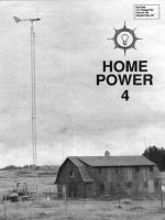
CoverThink About It
"You can't hold a man down without
staying down with him."
Booker T. Washington 1856-1915.
Joyce Eichenhofer's home, along
the Salmon River in California, is
powered by phoovoltaics and
hydro power.
Photo by Brian Green
B. Bonipulli
Twyla Browning
Sam Coleman
Donald Fallick
Jerry Fetterman
Brian Green
George Hagerman
Scott Hening
Phil Jergenson
Stan Krute
Alex Mason
Lynne Mowry-Patterson
George Patterson
Karen Perez
Richard Perez
John Pryor
Bob-O Schultze
Daniel Statnekov
Issue Printing by
Valley Web, Medford, OR
Home Power Magazine is a division of
Electron Connection Ltd. While we
strive for clarity and accuracy, we
assume no responsibility or liability for
the usage of this information.
Copyright © 1990 by Electron
Connection Ltd., POB 442, Medford,
OR 97501.
All rights reserved. Contents may not
be reprinted or otherwise reproduced
without written permission .
3
THE HANDS-ON JOURNAL OF HOME-MADE POWER
Access
Home Power #15 • February/March 1990
4
Home Power #15 • February/March 1990
From Us To YOU
From Us to YOU
I started to reach for its switch, then I paused
To enable the drama full play
The washer continued its haphazard march
Passed me by as it went on its way
But before it could crash it got to the end
Of its thick electric chord
Unplugged itself from the power supply
And didn't shake any more.
©1988 Daniel K. Statnekov
Statnekov Poem
As mentioned last time, this fifteenth issue is the
last free Home Power. Economic realities have
forced us to start charging subscriptions. Here's a
picture:
Though ad revenues have grown, the number of
issues we send out, and thus our costs, have been
growing even faster. Over 90% of our costs come
from printing, distribution, and equipment. Only
three of us get any kind of salary, and that's below
minimum wage. Everything else is lovingly
donated: articles, photographs, illustrations, and
miscellaneous good works. As you can tell by
examining the graph, if Home Power doesn't tie its
income to its circulation, we'll die. We can't let that
happen.
That's why we have to start charging. We think $6
a year is a reasonable price. That's just $1 per
issue. Many of you seem to agree. We've already
received a pile of paid subscriptions. Some are for
more than one year. Thank you all.
And a special thanks, as always, to our advertisers.
They've paid the freight this far. (And you readers
have helped them do it, by buying their goods and
services.) Many advertisers have shown their faith
in the Home Power future by buying new multiple-
insertion contracts. Thank you, business friends.
So: if you don't want to miss a single issue, send
in that $6 for each year of a paid subscription to
Home Power. You'll find the form on page 27.
We hope to see all you peaceful, planet-loving co-
conspirators next time out. The best is clearly yet
to come.
SK for the Home Power Crew
Subscribe Subscribe
Subscribe Oh Please Do
Subscribe Oh Yes Subscribe No Jive
1 5 10 15 20
Home Power Issue Number
Issues Distributed
Production & Distribution Expenses
Ad Income
Runaway Washing Machine
Daniel K. Statnekov
A terrible racket and clatter I heard
A moment or two ago
Got up from my desk to find the cause
See for myself and so
I walked from my study to the laundry room
To search for the source of the noise
And found that the washer had run away
From a dryer that sat with great poise
It was during the cycle that spins the clothes
When out of kilter it went
Hopping along on its one cubed foot
Its hoses were stretched and bent
Some imbalance, I gathered, had caused it to leave
Its appointed place in the room
Now it shimmied and shook, a machine run amuck
It wobble forcasting some doom
This Is The Last Free Issue
Of Home Power, So Please:
Subscribe Subscribe Subscribe
5
Home Power #15 • February/March 1990
Education
Teaching Kids about
Batteries &
Photovoltaics
George Hagerman
© 1990 by George Hagerman
iding in photo1 is the reflection of
high-voltage transmission lines that
carry nearly 1400 megawatts to
heavily populated northern Virginia. This
image captures the energy choices facing
today's youngsters in an increasingly
populous and resource-scarce world.
Disposable or renewable fuels? Centralized
or distributed generation? Next century's
energy picture will be shaped by this
decade's school children. Not all will be
utility or government planners, but all will be
energy consumers and voters. Will they
have the knowledge to make wise choices,
or even to ask the right questions?
Some are asking questions now!
An unexpected result of my free, one-line listing in the
Yellow Pages has been a small but steady stream of
requests for help on school projects. Last year, after
getting three calls in one week, I invited parents and their
kids to my office to show them some solar basics and
discuss their ideas. One young lady proposed to compare
the cost of producing hydrogen from electrolysis of water
by solar energy and by batteries. She borrowed a 2-watt
panel and did a fine job on her project. A sixth-grader
decided to build a miniature home power system - a small
cardboard house, a penlight bulb, two rechargeable AA
cells (in series), and two 6V/50mA mini-panels (in parallel)
on the roof. Well all this inspired me greatly, and I began
to realize that if we're going to stop the destruction of this
planet, education is where it's at. Then I received a call
from Lucy Negron-Evelyn.
The El Ingeniero Program
Lucy is Executive Director of Non-Profit Initiatives, Inc., in
Silver Spring, Maryland. Each year she conducts a
summer program called "El Ingeniero". This is a six-week
course for gifted Hispanic-American junior high school
students, funded by NASA as part of an effort that
encourages minorities to pursue careers in engineering.
The main focus of El Ingeniero '89 was hydraulics, but
Lucy asked if I could spend a few days teaching the kids
about solar energy. Jumping at the chance, it was soon
apparent that I had much to learn. This article attempts to
pass on some of the lessons.
H
Photo 1. Student-built battery chargers reinforce the principles learned
in this course. Photo by George Hagerman.
Overall Approach
The course consists of two main activities. Through lectures and
experiments, the students learn the relationship between solar cells, batteries,
and electrical loads. They learn about the design process that determines the
proper size, number, and arrangement of these components. This process is
the same,whether you are powering a portable tape player, a remote weather
station, an orbiting satellite, a house, a village medical clinic, or even a whole
community of homes and businesses.
As a second activity, each student designs and builds a battery charger for
their favorite battery-powered gadget. This is something that they can use the
rest of their lives, daily reinforcing the principles learned from lectures and
experiments. It is also a solar energy application that will save most students
the cost of 50-100 disposable batteries each year! Although the
environmental advantages of this are significant and important, it really hits
home when you can reach these kids in terms of their weekly allowance.
6
Home Power #15 • February/March 1990
Education
This article focuses on the lectures and experiments. The design,
construction and performance of the battery chargers built by El
Ingeniero '89 will be detailed in the next issue of Home Power.
Building the charger can be a course all by itself, as can the series
of lectures and experiments. The course is more effective if both
activities are combined, but lack of equipment or budget may make
this impossible. The lectures and experiments are presented here
in six sessions, but this may be modified to fit a particular teaching
schedule (e.g. regular school session vs. summer workshop).
This article describes the course not as I taught it, but as I would
teach it again. It was my first teaching experience, and there are
many things I'd do differently. Several new experiments have been
added, and although not yet used in a classroom, all have been
thoroughly tested to be sure they work.
Session 1 - Lecture on Batteries and Loads
The sun's rays are not always available when you need the power.
A reading lamp connected directly to a PV panel is a useless item.
The concept of battery storage is fundamental to the application of
solar energy (or any other intermittent resource).
Given the hydraulic focus of El Ingeniero '89, electrochemical
storage cells were introduced to the class as little tanks of water.
Voltage is analogous to the water's height (pressure), and capacity
is analogous to the tank's volume. Electric current is analogous to
the flow of water out of the tank, through a valve which represents
the load. As the cell discharges, the tank drains, and the water
level (cell voltage) drops - slowly for a small load (nearly closed
valve), quickly for a large load (nearly open valve).
The size of a cell (AA, C, D, etc.) is related to its capacity, not its
voltage. This fits the water tank analogy, since a AA cell and a C
cell are about the same height, but the C cell is significantly fatter.
Cell voltage is related to the nature of the electrochemical reaction -
1.5 volts for zinc-carbon, and 1.25 volts for nickel-cadmium.
This is an opportunity to take some of the mystery out of what goes
on inside a battery. Soak a piece of paper towel in lemon juice and
sandwich it between a nickel and a piece of aluminum foil. This
nickel-aluminum (Ni-Al) cell will develop an open-circuit potential of
about half a volt.
What's happening? When dissimilar metals are "bridged" by an
acid or alkaline solution, chemical reactions cause one metal to
develop a positive charge, the other a negative charge. The
negative charge is a build-up of free electrons, and depends on the
metals involved. For example, a nickel-iron (Ni-Fe) cell has twice
the voltage of a Ni-Al cell, which can be shown by replacing the
aluminum foil with a steel washer.
The nickel-cadmium (Ni-Cad) reaction is reversible, and Ni-Cad
cells are rechargeable. The discharge curves (voltage vs. capacity)
for zinc-carbon, alkaline, & Ni-Cad cells are compared. Zinc-carbon
and alkaline cells do behave like little cylindrical tanks of water - as
the cell drains, voltage drops almost linearly. Ni-Cad cells behave
more like hollow-stemmed wine glasses - very little change in
voltage until the cell is almost empty, and then voltage plummets as
the last bit of water drains from the glass stem. The electrical
consequences are explained for something like a flashlight.
Zinc-carbon & alkaline cells give early warning of their demise as
the light gets gradually dimmer. With Ni-Cads, you get a nice bright
light throughout most of the cells' life, and then, poof sudden
death.
The mathematical relationship between battery capacity, current
drain, and discharge time is explained, as is the meaning of a "C" or
"C/5" rate. A chart is drawn on the board showing the capacity of
different Ni-Cad cells. Simple questions are offered - "If two D cells
are used in a flashlight that draws 800 mA, how long will they
last?".
Finally, the class is shown how individual cells can be connected in
series (add voltages, same capacity) or parallel (same voltage, add
capacities).
It is explained how a certain threshold voltage is required to operate
any given load. Returning to our simple Ni-Fe cell, switch off the
classroom lights and show how four in series (Photo 2) have
enough voltage to power a light-emitting diode (LED). The class
should be able to guess how many Ni-Al cells are required to
produce the same LED brightness.
It should be emphasized that the ability to develop adequate
voltage depends only on the number of cells in series, and not their
size. For example, a tape recorder takes four fat C cells - will it run
off four tiny AAA cells?
The kids may be skeptical, so set it up in front of the class. Sure
enough, tunes start to emanate from the machine. The digital
multi-meter used earlier can now be used to show a current drain of
about 140 mA. Judging from the chart on the board, how long are
those AAA's going to last? Should the kids use a "C" or "C/5" rate
to calculate the answer? If Session 1 is in the morning and Session
2 is in the afternoon, have the students listen to the tape recorder
during lunch and see if it stops when they predicted it would.
Session 2 - Experiments With Batteries and Loads
Six experiments are set up at different locations in the room. The
students should work in groups of two or three. This way they can
help each other and talk about what they are doing. If the groups
are too large, then the quickest kids will do all of the "hands-on"
work, while those that are slower, or more shy, hold back.
Another way to ensure active participation is to give each student a
work sheet. This has specific questions for each experiment, which
can be answered only if the student DOES something, like
changing a wiring connection and reading a meter.
With only six experiments and 25 kids working in pairs, they can't all
be occupied at once. One solution is to divide the class in half, with
one group working on experiments, and the other on building their
battery chargers. Then half-way through the session, the two
groups switch.
Photo 2. A four-cell Ni-Fe battery made from nickels, steel
washers, and a weak acid electrolyte (vinegar also works).
When the bent wire of the LED shown is touched to the face
of the terminal nickel, it lights, and the voltage drops to about
1.8 volts. Stacked next to the Ni-Fe battery are eight Ni-Al
cells in series, fashioned from nickels and cut square pieces
of aluminum pie plate. Photo by George Hagerman.
7
Home Power #15 • February/March 1990
The six experiments and the principles they demonstrate are described
below. Component wiring connections are illustrated in Figure 1. Parts
access is given at the end of this article. Many of these components are
reused in the photovoltaic experiments shown latter photos.
Experiment BL1 demonstrates the different discharge characteristics of
Ni-Cad and zinc-carbon batteries, and the difference between open-circuit
and loaded voltage. It requires six AA Ni-Cads, two of which are fresh, two
of which are half-discharged, and two that are dead. Six zinc-carbon cells,
at comparable states of charge, are also required. Mark the cells with
letters or numbers ahead of time, but don't tell the kids which marks go with
which states of charge - they should determine that from voltage and/or
load behavior. A low-drain load, like an AM radio, can be used for
comparison with the high-drain lamp.
Experiment BL2 demonstrates the importance of connecting loads in
parallel rather than in series. The current drains of submerged and dry
pumps should be measured when they are individually in circuit, then
together in series, and finally together in parallel. When in series, the dry
pump acts like a bottleneck, limiting the amount of current flowing through
the circuit, thus reducing the output of the submerged pump. This also
shows that a loaded motor draws more current than a free-spinning one.
Experiment BL3 demonstrates the difference in current drain between a
motor starting from rest and one already running. Starting current will
always be more than running current, and depends on where the motor
comes to rest (relative position of magnets, windings, and such). This is of
considerable importance for motors that may be powered directly off
photovoltaic panels, which are current limited. Examples include fans for
venting cars or attics, and pumps for delivering water to irrigation systems.
Experiment BL4 demonstrates the effect of voltage on motor speed. As a
load, the motor may be considered a valve for electrons. When the voltage
(or electron pressure) is increased, more electrons flow through the valve
per unit time. As long as the mechanical load on the motor doesn't
change, this greater flow of electrons results in more speed. Stall the
motor, and the valve opens wide, draining the battery.
Experiment BL5 demonstrates the effect of wire resistance on voltage
drop. Again, the flow of electrons in a wire may be likened to that of water
in a pipe. Electrons start their trip at a cell's negative terminal with a certain
amount of potential energy (voltage), which is converted to other forms
(heat, light, sound, shaft horsepower) as they travel through the circuit.
This potential energy is completely lost by the time they reach the cell's
positive terminal. Ideally, very little energy should be lost as they flow to
and from the load. If the pipe (or wire) is too small, significant amounts will
be lost to friction (heat), and not as much will be available to operate the
load. When all four spools of wire are in circuit, two additional Ni-Cad cells
are required to properly operate the load. Replace any one of these six
good cells with a dead Ni-Cad. This shows how a "dead battery" may result
from only one bad cell.
Experiment BL6 demonstrates the effect of mechanical loading on the
current drain of a motor. Most motors don't spin freely, but do work like
lifting weights, pushing vehicles, and moving air or water. This experiment
uses a commercially available motorized game that lifts little plastic
dolphins to the top of a spiral track. They roll down to the bottom, where
they are picked up by a slowly spinning wheel and carried to the top again.
The wheel spins behind a cardboard sheet. Magnets on the wheel rim
pick up the dolphins, which have small magnets on their sides. As the
dolphins slide along the cardboard on their way to the top of the track,
friction loads the motor, causing an 80 mA. jump per dolphin. These
"leaping" dolphins are fun to watch and teach an important principle that
applies to many practical situations: an electric winch lifting a heavier
weight, a solar car driving up an increasingly steep hill, or a pump filling a
higher reservoir. In all cases the current drain will increase. If the voltage
source can't deliver any more current, then the rate of lifting will slow, the
car's speed will drop, and a sea-level gusher will turn into a mountain-top
trickle.
LAMP
+-
NiCd
+-
NiCd
0-5VDC
+-
+-
0-1A.
+-
NiCd
+-
NiCd
+ -
+ -
+-
0-150mA.
+-
+-
NiCd
+-
NiCd
+-
0 TO 25 Ω RHEOSTAT
+-
+-
+
-
NiCd
+
-
NiCd
+
-
NiCd
+
-
NiCd
+-
NiCd
+-
NiCd
50 FT. SPOOLS OF #30 WIRE
ADDITIONAL
CELLS
CASSETTE
+-
0-1 A.
+-
+-
NiCd
+-
NiCd
GAME
MOTOR
+-
NiCd
+-
NiCd
+-
NiCd
+-
NiCd
+- +-
MOTOR
Experiment BL1
Experiment BL2
Experiment BL3
Experiment BL4
Experiment BL5
Experiment BL6
NICKEL- CADMIUM
CELL AND HOLDER
+-
NiCd
LEGEND
CONNECTION
MADE BY STUDENT
WITH ALLIGATOR
CLIP & WIRE
PARALLEL
CONNECTION OF DRY
PUMP IS SHOWN HERE
+-
+-
ZINC-CARBON CELLS
0-1A.
-+
MOTOR
0-150mA.
0-5VDC
AM RADIO
Figure 1. Six Battery and Load experiments.
Education
8
Home Power #15 • February/March 1990
Education
Session 3 - Lecture on Photovoltaics
Placing photovoltaics into context with other renewable energy
technologies requires a brief overview of the four main methods for
directly harnessing the sun's rays. These are passive solar heating
(via solar building design), active solar heating (via special
collectors for air or water), solar thermal electric (parabolic reflectors
producing high-temperature steam running turbine/generators), and
photovoltaics (direct conversion of photon energy into electron
potential). Because wind is a result of unequal heating of the
earth's surface by the sun, and waves are generated by wind
blowing over water, these are also forms of solar energy.
The photovoltaic (PV) effect is explained very simply: when light
strikes a PV cell, it "kicks" electrons up to the surface layer from a
deeper layer. Just as the voltage of an electrochemical cell depends
on the two metals involved, the potential energy developed by a PV
cell depends on the material composition of its upper and lower
layers. The characteristic potential of silicon-based PV cells is
about half a volt. At low levels of illumination (say on an overcast
day), the voltage of a PV cell depends on the intensity of light
striking its surface, but over most of its useful operating range,
voltage varies only slightly with light intensity. On the other hand,
the amount of current delivered by the cell depends strongly (and
linearly) on light intensity. (the number of photons arriving per unit
area per unit time). No matter how much potential energy it has, an
electron cannot leave the cell's surface until a photon arrives to
"kick" another one up from the lower layer to take its place.
An electron also can't leave if it doesn't have anywhere to go, so in
an open circuit, electrons "kicked" up by newly arriving photons fall
back into the lower layer, until a circuit is completed. Open circuit
PV cells behave much like electrochemical cells. Connected to a
load their behavior is markedly different. For the power drains used
here, a Ni-Cad cell's ability to deliver current is unlimited. A tiny
AAA cell can deliver as much current as a big bad D cell; not for
nearly as long, but it can still deliver. The current delivered by a PV
cell is limited by the rate of photon arrival.
Therefore, except when very lightly loaded (almost closed electron
valve), the PV cell is a constant-current source. The current flowing
through a medium load (half-open electron valve) is almost the
same as that flowing through a short circuit (wide open electron
valve). No matter how open the valve is, the rate of electron flow
(current) is governed by the rate of photon arrival, which is the
product of cell area and light intensity.
Light intensity is affected by shading and angle of incidence. If
photons are absorbed or reflected by the atmosphere, clouds, tree
branches, or glass, then their rate of arrival at a PV cell is reduced.
Even if there is nothing between the cell and its light source, the
light intensity is affected by the angle at which light strikes the cell's
surface. This can be illustrated on a chalkboard by drawing a beam
of parallel rays striking a plane at various angles of incidence.
Thus, less solar energy reaches the earth's surface during the
winter; not only because the days are shorter, but also because the
sun is at a lower angle in the sky. This reduces the angle of
incidence and also means that the sun's rays have to pass through
more of the atmosphere.
Just as a battery is a series/parallel combination of electrochemical
cells, a solar panel is a series/parallel combination of PV cells.
Panel voltage, like battery voltage, can be increased by wiring cells
in series. Wiring PV cells in parallel increases the amount of current
that the panel can deliver under a given light intensity, having
exactly the same effect as increasing the cell's area.
At this point, break out a bunch of different PV cells and panels.
The cells (protected in clear plastic boxes) can be handed around
the class. Note the grid of fine wires on the cell's surface, which
collects electrons "kicked" up by the light. This is the negative
terminal. The metal surface on the back side of a cell is it's positive
terminal. Briefly describe the different silicon cell types: single
crystal, polycrystalline, and thin-film. Have the kids look at the
panels. Can they distinguish series and parallel cell connections?
If it happens to be sunny outside, show that panels of the same size
may be high-voltage/low-current or low-voltage/high-current. What
does this imply about series vs. parallel cell wiring?
Also if you can get outside, demonstrate the constant-current
feature of PV panels. Using the same tape recorder that drew
about 140 mA from the Ni-Cad cells, connect a PV panel to its
battery compartment terminals. Show the effect of tilt angle. Hold
the panel at an angle just above the threshold at which the tape
slows noticeably. Have one of the kids move the jumper cables
from the tape recorder to a current meter, and note the short-circuit
current. Can they guess beforehand what it will be? At lesser
angles of incidence, the rate of photon arrival doesn't send enough
electrons around the circuit to operate the load, eventhough its
electron valve is open enough to accommodate them.
Tape recorders are great for showing all sorts of things. More
importantly, if you put on a tape with tunes that the kids know, you'll
grab their attention immediately. There's nothing like a little
"Straight Up" by Paula Abdul (from Forever Your Girl, copyright
1988 by Virgin Records America, Inc.) to get feet tapping. PVs
should make you feel like dancin'!
Session 4 - Experiments With Photovoltaics
This is the one session that must be held outside on a bright day.
What is bright"? If you can see sharp edged shadows on the
ground for at least five out of every ten minutes, then all of the PV
experiments will work.
Experiment PV1 demonstrates that decreasing light intensity
strongly affects current output, but it has little effect on voltage
except at the lowest illumination levels. First, the panel is tilted at
various angles, such that the students can collect enough data
points to plot open-circuit voltage vs. short-circuit current. The
panel is then returned to a position that is perpendicular to the sun's
rays, and the effects of increasing cloud thickness are simulated by
placing one, two, or three layers of translucent white foam over the
panel. Are transmission efficiencies of multiple layers additive or
multiplicative? Finally, a piece of opaque cardboard is used to
completely shadow a portion of the panel. It has different effects,
depending on whether it is oriented vertically or horizontally.
Experiment PV2 demonstrates that if just one cell in a string of
series cells is completely shadowed, then it develops a high
resistance, causing a large voltage drop when the panel is under
load. In this way, it has the same effect as a dead electrochemical
cell in an otherwise good battery. The panel shown I used evidently
has a few cells that are not of such high quality, since Paula still
played up to tempo when one of these lesser-quality cells was
shaded. Partially shading many cells in the panel has much less
effect than completely shading just one good cell. Since even a
single bare branch can cast a shadow large enough to cover an
entire cell, the moral of the story is: avoid trees, and be particularly
sure that they won't shade the panel in winter, when shadows are
longest.
Experiment PV3 simulates a solar powered irrigation system and
the effect of starting vs. running current on system operation.
Orient the panel so it is perpendicular to the sun's rays. Tilt the
panel back until output from the pump stops just shy of the tip of the
clear plastic tubing that comes with the pump. Note the angle, and
tilt the panel back even farther, so that the sun "sets" completely,
and the pump motor stops. Now slowly raise the panel to the angle
9
Home Power #15 • February/March 1990
Education
noted earlier. Depending on what position the pump motor came to
rest, it may be that there is not enough PV current to start the pump
motor. The angle of incidence may have to be much higher, and it
will be much closer to "solar noon" before the system starts to
operate. If you want to keep the experimental set-up dry, it is better
to use something deep like a cottage cheese container, rather than
the shallow bowl shown in the photo. The clear plastic tubing
should be duct-taped to the inside wall of the container, so that the
pump is held level.
Experiment PV4 demonstrates the effects of parallel and series
connection of individual PV cells. First, short-circuit current and
open-circuit voltage are measured. Then a submerged pump is
connected, and it will be seen that wiring the PV cells in parallel has
no effect on pump output, but wiring them in series does. This
reinforces the principle already shown with batteries, that increasing
voltage increases motor speed for a given mechanical load. Now
connect a dry pump in parallel. Do the students recall why not in
series? If the light intensity is high enough, it can be seen that the
second pump will have no effect on the first one's performance as
long as both are running smoothly. If the dry one is stalled by
stopping its impeller with a toothpick, the output of the other pump
drops dramatically. If current delivery is limited (as it is with PVs),
and one valve opens wide (stalled motor), most of the electrons will
take the path of least resistance, leaving the other load without
adequate current.
Experiment PV5 demonstrates that PVs can recharge Ni-Cads,
and that current into the Ni-Cad equals current out (or very nearly
so). The procedure is as follows. First, a dead Ni-Cad is connected
to a motor, which has a 4.4-ohm resistor across its terminals so that
it will only run for a few seconds on the "rebound" voltage of the
dead Ni-Cad. The motor I used draws 10 to 15 mA at 1.2 volts
without the shunt resistor, 100 mA with it. The Ni-Cad is then
charged for two to four minutes, depending on sky conditions. The
trick here is to continuously adjust the tilt of the panel, so that the
charging current remains at exactly 50 or 100 mA. By casting a
"weather eye" to the sky during this period, the student can
anticipate upcoming tilt adjustments and will start to gain a feel for
the effects of clouds and angle of incidence on PV output. The
newly charged battery is then connected to the motor, again
monitoring the current flow. A watch with a second hand (or digital
second counter) is used to measure the time it takes the current to
drop from 100 mA to 95 mA (it will plummet very quickly after that,
and the motor will stop; the student should then switch the rotary
dial on the current meter to "OFF" in order to avoid excessive
discharge of the Ni-Cad).
Experiment PV6 demonstrates the effect of PV voltage on how
much charging current flows through a battery. It also demonstrates
the need for (and the energy cost of) a blocking diode. First, the
battery open-circuit voltage is measured, as well as the open-circuit
voltage and short-circuit current of six, five, four, three, and two PV
cells in series. This should be done with and without the diode.
The diode can be taken out of circuit simply by clipping the jumper
cable below, rather than above, the barrel of the diode, as shown in
the photo. Then, battery charging current is measured for each of
the different numbers of PV cells. This should be done without the
diode first, so that the negative current flow (battery discharging into
PV cells) can be seen for the two-cell configuration. Then the diode
is placed in circuit, and it can be seen that this acts like a one-way
valve to electron flow. As the student works back up to six PV cells,
it will be seen that there is a price to be paid for this protection.
Session 5 - Quiz & Session 6 - Wrap-Up
Painful as it may seem, this is the best way for you to learn what
you taught, rather than what you think you taught. Try to set up test
problems that force the students to apply the principles that they
Experiment PV1 - Effects of tilting and shading on open
circuit voltage and short circuit current.
Experiment PV3 - Effect of tilting on the ability of the PV to
start a pump (sunrise) and keep it running (sunset).
Experiment PV2 - Effects of shading on PV cell resistance
and panel's ability to operate a load.
ALL PHOTOS BY GEORGE HAGERMAN.
10
Home Power #15 • February/March 1990
Education
Experiment PV4 - PV cells in series and parallel.
Experiment PV6 - Battery charging current as a function of
number of PV cells in series. Also, the need for(and energy
cost of) a blocking diode.
Experiment PV5 - The mA minutes delivered to a battery
under PV charge will almost equal the mA minutes
discharged through the motor.
ALL PHOTOS BY GEORGE HAGERMAN.
have learned. You may even want to base these on some
additional experiments. Should the students be told ahead of time,
so they can study for it? Although surprise quizzes are not popular,
they probably are a better measure of the actual working knowledge
of a student. On the other hand, reviewing for a test is a valuable
learning exercise in itself. What to do? Toss a coin.
Return the quiz during session 6 and review any class-wide weak
points. Open the floor for discussion. You may also want to hand
out materials for further reading. These can include ideas for
science fair projects.
Access - Experimental Equipment
The components needed to setup the experiments described in this
article are specified in Table 1. It should be noted that some
components (500mA. PV cells, 0-5 VDC meter, 0-1 Amp. meter,
and motor with color wheel, all shown in the photos) came from a
"Photovoltaic Demonstration Kit" made by Solarex Corporation (#
ES 602073005), which is no longer available. Therefore, other
sources have been located for these components.
The 500 mA. solar cells are really too large, but I used them
because they came with the Solarex kit. A better choice for
experiment PV4 would be a 300 mA. cell. Bare cells require
soldering, whereas the encased cells have wire leads already
installed. The best choice for experiment PV6 are encased 100mA.
cells. One advantage of these cells is that the Radio Shack meter
can be used instead of the higher priced 0-1 Amp. meters.
Meters should have a large enough range to measure the maximum
expected voltage or current, yet not so large that only tiny needle
movements result from experimental manipulations. The 15mA. DC
motor specified in Table 1 is a close duplicate of the Solarex kit
motor, but it is not well matched to the 0-150 mA. meter. A better
choice may be the 80 mA. motor, but this has not been tested.
Regardless of motor, be sure to buy either color wheels or
propellers, so students can plainly see changes in motor speed.
For one dollar, Solar World sells a package of three color wheels
with shaft adaptors or two friction-fit propellers. The Edmund DC
pump at 2.5 Volts (experiment BL2) draws 120 mA. dry , 360 mA.
submerged, and >800 mA. stalled. At 1.0 Volts (experiment PV4), it
draws 90 mA. dry, 180 mA. submerged, and >300 mA. stalled.
If you would like to design other experiments using different sizes of
PV cells, try Solar World (10 to 650 mA. output) or Astropower (2.0
A. output). A good paperback text for high school or college
students is The Solarex Guide to Solar Electricity. Although
out-of-print, Solar George has a large stock of these for sale five
dollars each (less in volume). Even more intriguing to the educator,
Solar George has developed a 36-cell, 5-watt, "build-your-own"
panel kit, which retails for about $35.00.
Access - Other Ideas for Energy Education
Here is a short, but by no means exhaustive, selection of materials
that I've come across.
Solar Energy Experiments for High School and College Students,
by Thomas W. Norton, copyright 1977, Rodale Press, Emmaus, PA.
Most of the experiments are concerned with solar heating, although
some interesting exercises in solar astronomy and measurements
are also included.
Energy Education Guidebook, prepared by Design Alternatives, Inc.
of Washington, DC, under contract to the Community Services
Administration. It is available from the National Appropriate
Technology Assistance Service (NATAS), P.O. Box 2525, Butte,
MT 59702, tel. (800) 428-2525 (in Montana, dial 800-428-1718).
This book describes a variety of projects, including some other
renewable technologies, like a small wind generator and a simple
bio-gas digester. NATAS can also provide an extensive
bibliography of other energy education materials and resources.
11
Home Power #15 • February/March 1990
Education
PV Cells & Panels Volts Amps Supplier Part # Cost Experiment #
Thin-film Panel 12.00 0.110 Solarex SA-0680 $16.70 PV1
Solarex Panel 11.00 0.350 AEE SX-2 $26.00 PV2
Solar Energizer 3.00 0.300 Solar George NA $15.00 PV3
Bare Cell 0.50 0.275 Solar World SC-6 2/$5.00 PV4
Encased Cell 0.50 0.300 Solar World 3-300 $4.50 PV4
Bare Cell 0.55 0.300 Radio Shack 276-124 $3.95 PV4
Thin-film Panel 10.50 0.170 Chronar CP06-0606A $7.90 PV5
Encased Cell 0.50 0.100 Solar World 1-100 6/$9.00 PV6
Other Components Supplier Part # Cost Experiment #
AA NiCad Cell (New) Radio Shack 23-125 2/$4.69 BL1-6 &PV6
AA NiCad Cell (New) All Electronics NCB-AA $2.00 BL1-6 &PV6
AA NiCad Cell (Used) All Electronics NCB-AAU $1.00 BL1-6 &PV6
Alligator Clip Jumpers All Electronics MTL-10 10/$2.50 ALL
Alligator Clip Jumpers Radio Shack 278-1156 10/$3.99 ALL
Battery Holder 1-AA cell Radio Shack 270-401 $0.59 BL1-6 &PV5-6
Battery Holder 4-AA cell Radio Shack 270-391 $1.19 BL5
DC Motor (15mA. idle at 0.5VDC) Solar World MC 05/07 $4.50 BL3-4 & PV5
DC Motor (80mA. at 0.5 VDC) Solar World MRE-260 $2.10 BL3-4 & PV5
DC Pump (120MA. dry idle at 2.5VDC) Edmund Scientific J50,345 $6.95 BL2 & PV1&3
Dolphin Game ("Jumping Flipper™") Spencer Gifts 702886 $16.99 BL6
Lamp (#243- 270mA. at 2.3VDC) Radio Shack 272-1124 2/$0.99 BL1
Lamp Base (E-10 with terminals) Radio Shack 272-357 $0.79 BL1
Multi-Meter (Digital with large display) Radio Shack 22-193 $69.95 Calibration
Multi- Meter (0-150mA., analog) Radio Shack 22-212 $12.95 BL3-4 & PV1,5
Multi- Meter (0-150mA., analog) Radio Shack 28-4012 $7.95 BL3-4 & PV1,5
Panel Meter (0-1Amp, analog) Frey Scientific Co. 16224 $17.25 BL1,2,6 & PV4
Panel Meter (0-5VDC, analog) Frey Scientific Co. 16213 $17.25 BL1,5 & PV4,6
Radio AM (40mA. at 4.5VDC) Randix PWR-7 $1.60 BL1
Rheostat (0-25 Ω at 2 Watts) Radio Shack 271-265 $2.99 BL3
Wire (insulated #30, 50 FT spool) Radio Shack 278-501 $2.39 BL5
Table 1. Equipment for battery, load and PV experiments
Supplier Access
AEE
Alternative Energy Engineering
POB 339
Redway, CA 95560
707-923-2277 • 800-777-6609
All Electronics Corp.
POB 567
Van Nuys, CA 91408
818-904-0524 • 800-826-5432
Astro Power
30 Lovett Avenue
Newark, DE 19711
302-366-0400
Chronar
POB 177
Princeton, NJ 08542
609-799-8800
Edmund Scientific
101 E. Glouchester Pike
Barrington, NJ 08007
609-573-6250
Frey Scientific Co.
905 Hickory Lane
Mansfield, OH 44905
419-589-9905
Radio Shack
500 One Tandy Center
Fort Worth, TX 76102
817-390-3011
Randix Industries Ltd.
Granite Park, Fortune Blvd.
Milford, MA 01257
508-478-8989
Solar George
George Newberry
POB 417
Big Pine Key, FL 33043
305-872-3976
Solar World
2807 North Prospect
Colorado Springs, CO 80907
719-635-5125
Solarex Corporation
1335 Piccard Drive
Rockville, MD 20850
301-948-0202
Spencer Gifts
1050 Black Horse Pike
Pleasantville, NJ 08232
609-645-3300
The Florida Solar Energy Center, in cooperation with the Governor's Energy Office, has prepared the
Florida Middle School Education Project, which describes a variety of classroom, homework, and
experimental activities dealing with energy production, consumption, and conservation. It is available
from the Public Information Office, Florida Solar Energy Center, 300 State Road 401, Cape Canaveral,
FL 32920, tel. (407) 783-0300.
Finally, Jim Masker, who teaches at a private school in California, has developed his own short course
in photovoltaics, including among other things, a solar-powered boat race across a swimming pool, and
the design of a "home power" system for a dormitory room. He has also put together a self-contained
kit (including an intense light source) for PV experiments. Descriptions of both are available from Jim
Masker, Cate School, P.O. Box 5005, Carpinteria, CA 93013, tel. (805) 684-4127.
Jim and I have been discussing the possibility of convening a short workshop at the Willits Energy Fair,
where energy educators could get together, share ideas from their "bag of tricks", and brainstorm some
new ones. If you've had experience teaching kids (or adults) about energy, and would be interested in
attending such a workshop, then please contact either one of us. George Hagerman, SEASUN Power
Systems, 124 East Rosemont Ave., Alexandria, VA 22301,telephone 703-549-8067.
Acknowledgements
First, I'd like to thank Richard and Karen Perez for their encouragement, patience, creative layout, and
meticulous editing. Their input was invaluable. Many thanks also to Michael Meredith, a neighbor here
in northern Virginia (see his Micro Ad), who definitely has the talent to put together a short course in
solar thermal electricity. He loaned me a 12-inch multi-faceted parabolic mirror that fascinated the kids.
A coil of copper tubing is located at the mirror's focus, such that when water is slowly fed through the
coil, a puff of steam comes out the other side. Truly ingenious! I'd also like to thank Dr. John
12
Home Power #15 • February/March 1990
Education
Wohlgemuth, who arranged a special tour of the
Solarex Technical Center in Frederick, Maryland,
where students could see how silicon is turned into
solar cells and panels. The tour was well-organized
and quite impressive.
Last, but certainly not least, I'd like to thank Lucy
Negron-Evelyn for giving me the opportunity to teach
the students of El Ingeniero '89. These kids were
wonderful, and their attentiveness and eagerness to
learn convinced me that batteries and photovoltaics
were not "too technical" to teach at the junior high
school level. Their positive response and hard work
inspired me to really polish the course, as it is
presented here. I'm only sorry that I can't teach them
again. Assistant Instructor, Edgar Hurtado, helped in
a variety of ways, as did Lucy's teaching assistants:
Alan, Rosa, and Janet. Thanks guys!!
A HELIOTROPE GENERAL
ANNOUNCEMENT!
There is a new emerging
technology that will soon change
power conversion for remote
homes. No more heavy
transformers, no more pie in the
sky power ratings for inverters
and built-in battery chargers, no
more 60 cycle buzz either.
Introducing the HC-75,
Helio-Charger, battery charger for
12 and 24 volt systems. 75
Amps, 0.5 cubic feet, 9 pounds.
Two different voltage outputs
available for LEAD ACID and
NI-CAD batteries. Small, light and
to the point, and the output is
unaffected by peak generator
voltage. Simple and reliable
charging. Call
MARK ALBERT for
details on the HC-75,
another fine product
from Heliotrope
General.
For data, write 3733 Kenora Drive, Spring Valley, CA 92077
Call (619) 460-3930
TOLL FREE in CA (800) 552-8838 • Outside CA (800) 854-2074
FAX (619) 460-9211
HELIOTROPE
GENERAL
KYOCERA AD
SUNAMP
POWER
COMPANY
This is the last FREE issue of Home Power. If you want to keep getting
HP and think it's worth six bucks a year, then SUBSCRIBE NOW!
13
Home Power #15 • February/March 1990
Support HP Advertisers!
14
Home Power #15 • February/March 1990
Systems
PV/Hydro Systems and a visit to the Lil Otto Hydroworks!
Richard Perez
was delighted when Bob-O Schultze and Otto Eichenhofer invited us to visit some PV/Hydro systems
along the Salmon River. The Salmon River runs madly through northern California, and if you want
power along the River, then you make your own. The independent folks living along the Salmon have
been doing just that. Brian Green, our HP photographer, and I saddled up and drove up and down the icy
mountain roads to the little town of Cecilville, CA. Everyone in Cecilville makes their own power. The
nearest utility is over thirty miles away- through some of the most rugged mountains in the USA.
The Cecilville Scene
We met Bob-O and Kathleen at the General Store in Cecilville (pop.
20). Kathleen, Bob-O's wife, was doing the driving since Bob-O
was recovering from an argument with a large tree that nearly cost
him his leg. The Cecilville Store, hub of all neighborhood activity, is
powered by a 15kW. diesel engine generator. While few folks live
inside the micro village of Cecilville itself, many live up and down
the serpentine one-lane road that follows the Salmon River's
course. Almost all the folks along "the River" have
engine/generators. Many are using micro or nano hydro systems
and photovoltaics.
Joyce Eichenhofer's Home
Our first stop was the home of Joyce Eichenhofer, which is pictured
on the cover of this issue. Joyce lives right next to the Salmon. Her
beautiful house is powered by home-made electricity.
Joyce uses a combination of three power sources. Visible on her
roof are four photovoltaic panels (2 @ Kyocera 48 Watt panels and
2 @ Solavolt 36 Watt panels). This PV array produces about 168
Watts, or about 12 Amperes at 13.5 VDC, when under full sun.
Bob-O mentioned that at Joyce's location the Winter sun only
shines on the panels for about 2 hours daily (Summer performance
is much better). During the Winter, Joyce falls back on her Lil Otto
Hydroelectric system for power. Lil Otto turbines are made by her
son, Otto, so she gets factory service and no doubt a right price.
Her Lil Otto turbine runs on a working pressure of 18 PSI generated
by about 40 feet of head. She uses a 9/32" nozzle, consuming
about 9.7 gallons per minute, to produce an output of 1.35
Amperes. Joyce's turbine is producing about 18 Watts, with a daily
output of 430 Watt-hours. During the Winter, Joyce's PV panels
produce a daily average of about 336 Watt-hours because the
mountains shade them most of the time. So during the Winter,
Joyce's nanohydro turbine produces more electricity than the PV
array (even though the PV array has a peak output almost ten times
greater). The third power source is an aged 2 cylinder diesel
engine/generator. When all else fails, Joyce can fall back on the
generator to source her system. This 6 kW. generator also sources
the machine tools in the Lil Otto Hydroworks! building nearby (more
on this later).
Joyce uses lead-acid batteries, housed in her basement, to store
the power her PVs and nanohydro produce. She uses two Trojan
L-16s, a 200 Ampere-hour, 12 Volt Interstate diesel starting battery,
and an assortment of other 12 Volt batteries. Total capacity of her
battery pack is about 500 Ampere-hours at 12 VDC. Joyce's
system also uses a brand spanking new Trace 2012 inverter to
convert the DC stored power in the batteries into 120 vac for her
appliances. Also located in the basement is a Heliotrope CC60 PV
charge controller that rides herd on the array's output. I asked Otto
why he had such a large (60 Ampere) control on the 12 Amp array.
He replied he's looking forward to expanding his mom's array soon.
Electrically speaking, Joyce has all the conveniences. For
example, her refrigerator/freezer is a super-efficient, 12 VDC
operated, SunFrost RF-12. This refrigerator/freezer consumes
about 290 Watt-hours daily in Joyce's kitchen. Otto is busy taking
data on the SunFrost's performance with a motor run-time meter.
Joyce's home is primarily wired for 120 vac, but there are a few
special 12 VDC circuits directly supplied by the battery. Joyce uses
12 VDC for a fluorescent light on the ceiling of the kitchen, for her
CB radio and for the SunFrost. Entertainment electronics are
powered by 120 vac from the Trace inverter. Joyce runs her
washing machine when Otto's out in the shop and the large
generator is operating.
The Lil Otto Hydroworks
We also visited the shop that Bob-O and Otto use to make their
nanohydro turbines. Against a background of machine tools, ranks
of Lil Otto turbines march down their assembly line, jump into
boxes, and travel to streams & springs round the world. It was
inspiring to see the obvious care and thought that goes into their
manufacture. Bob-O and Otto start out with a permanent magnet
I
Bob-O Schultze and Otto Eichenhofer sit under Joyce's back
porch. Located between them, a Lil Otto turbine produces
18 Watts of power while consuming only 9.7 gallons of water
per minute (40 feet head). Photo by Brian Green.
15
Home Power #15 • February/March 1990
Systems
Bosch generator. This generator is coupled to a molded turbine
wheel made by Powerhouse Paul Cunningham at Energy Systems
and Design in Canada (see ad this issue). The generator is housed
in a sealed PVC pipe case. Bob-O and Otto are now installing a
new "gravity tube" along the shaft of the unit to eliminate water
infiltration to the generator's inards. The unit is supplied with a
blocking diode (to keep the generator from becoming a motor) and
filtration to keep electrical noise from interfering with radios and
TVs. There is a 0-8 Ampere output meter on Lil Otto's top so
operation can be checked at a glance.
The Lil Otto units will produce up to five amperes, with enough head
and flow. Where this turbine really shines is in the gallons per
minute required for operation. This turbine consumes very little
water. For performance data on these turbines, see HP#13 "Things
that Work!" article about Lil Otto. Bob-O and Otto deserve credit for
intelligent and efficient use of off-the-shelf components in
manufacturing Lil Otto turbines. For example, the housings are
sections of stock PVC pipe. The various sized nozzles used (and
there is one to fit every site) are stock Rainbird™ sprinkler nozzles.
Well, we were ready for more. Obviously Otto's mom, Joyce, was
satisfied with her PV/Hydro system and was justly proud of her
inventive son. But she's Otto's mom and could be biased. We
asked to talk to some paying customers. Bob-O smiled and invited
us on a trip down River.
Getting down River
This turned out to be an adventure in itself. The road that winds
along the Salmon from Cecilville to Forks of Salmon is mostly one
lane with sharp 100+ foot drops into the surging river. Kathleen
drove first because she had a CB radio in her car. The CB radio is
essential because you have to know when a log truck is coming so
that you can pull out in a place that is wide enough for the log truck
to pass. Kathleen (also a ham radio op) kept us advised of traffic
on our 2 meter ham radios. As I drove along I had trouble keeping
my eyes on the road, the scenery was too distracting. Rock cliffs
plunged down into the foaming river. From bends in the road, large
mountain meadows filled with trees soothed my senses. I like
mountains and the peace they give. The Salmon Mountains are
very beautiful. It is easy to understand why these folks live in such
a remote place.
Terry & Betty Ann Hanauer's Home
After about 30 minutes of driving we arrived at another PV/Hydro
system at the home of Terry and Betty Ann. Betty Ann, a school
teacher, took time off to show us her well built and immaculate
home. This large, owner built home, houses their family of six
people. Their home has been powered by site-generated electricity
since 1987.
Power sources at the Hanauer home are much the same as at
Joyce Eichenhofer's home. The Hanauers use a PV array
composed of three 36 Watt Solavolt panels. On an average day
this array makes about 600 Watt-hours of electricity. These panels
are fortunately located on one of the sunnier locations along the
river. Terry & Betty Ann also use a Lil Otto turbine. This Lil Otto,
however, is located at a much better site than Joyce's. At Terry &
Betty Ann's site the turbine has 72 feet of head to work with (32 PSI
dynamic pressure). Here the turbine produces 2.5 Amperes with a
1/4 inch diameter nozzle consuming 10 gallons per minute. Terry &
Betty Ann's turbine produces 33 Watts and makes 810 Watt-hours
of electricity per day. Combined production of both the PV array
and the nanohydro turbine is about 1,400 Watt-hours daily, and
that's enough to run a household with four kids! Terry & Betty Ann
also use an engine/generator (Onan two cylinder 6kW. powered by
propane) for extended cloudy periods and times of intense power
consumption.
Terry & Betty Ann use a battery pack of four Trojan L-16 batteries to
store the power produced by Lil Otto and the PV array. This battery
pack is housed in an insulated blister on the outside of the house.
Bob-O Schultze fabricated a custom regulator for the PV array. A
Trace 2012 inverter with 110 Ampere battery charger is used to
power the house and recharge the batteries when the generator is
running. Betty Ann says that with four kids, the washing machine
gets alot of action. She starts the generator, does the washing and
refills her batteries all at the same time.
The Hanauer's home is wired for 12 VDC lighting, which spends
lotsa time operating. The Sabir refrigerator/freezer is powered by
propane. Betty Ann is a gourmet cook and her kitchen is filled with
good things. Among these things are many kitchen appliances
(food processors, grinder, mixers, blenders and such) that all run
from the inverter. Betty Ann said that cooking was more enjoyable
because she didn't have to start the generator just for a few minutes
of kitchen appliance use. Everyone likes not having the generator
An exploded view of a Lil Otto turbine showing the various
sub-assemblies inside. Photo by Brian Green.
Fly cutting the water
intake hole in the
side of a Lil Otto
case. This is a
delicate operation
that must be done
precisely because it
determines the
position where the
water jet hits the
turbine wheel.
Photo by Brian Green.
16
Home Power #15 • February/March 1990
Systems
Lil Otto on the rocks. Since the entire turbine weighs less
than 20 pounds, it's easy to mount. Here Lil Otto sits on a
pile of rocks. Photo by Brian Green.
Betty Ann Hanauer in her kitchen. Photo by Brian Green.
yammering while reading or listen to the stereo.
Hot water is produced by a large solar collector located next to the
PV array. Betty Ann told us that in the Summer, even with wash
and four kids to bathe, there is more than enough hot water being
produced by their solar collector to meet their needs.
Lessons Learned
From experience, the folks along the river have learned a great deal
about making their own power. They've learned that even a trickle
can be turned into a watt. They learned to use a variety of natural
power sources without damaging their environment. And certainly,
they've learned contentment and happiness.
Last free issue of HP. Either subscribe or miss out!
17
Home Power #15 • February/March 1990
Hydro
Siting for Nano-Hydro- A primer
Bob-O Schultze KG6MM
ano-Hydro is the ability to generate 3 Amps or less of hydropower at least some of the year. An
amazing number of rural, and especially mountainous, homesites have this capability. Most anyone
who has a couple of acres in the mountains somewhere has seen the phenomenon of little springs
popping up everywhere after a couple of good rains or during snowmelt. True, most of them seem to pop
up in the driveway somewhere or worse, in the cellar, but since most folks tend to build toward the base
of the hill rather than the top, a lot of those seasonal creeks or springs can be harnessed to provide power
during a time of year when the PV's aren't exactly boiling the batteries! The really fun thing is that as long
as the water flows, you're producing power-24 hours a day and the sun doesn't have to shine at the time.
Why Nano-Hydro?
There are some nice advantages to a nano-hydro system. In most
micro and larger hydro installations half of the cost of the system is
the pipe. Usually, somewhere between 2" - 6" PVC is used in order
to get enough water to the wheel without incurring horrendous
pressure losses. Priced any 6"PVC pipe lately? Whew! With a nano
system, 2" pipe would be the high side with most systems running
1-11/2" pipe. I've seen a fair number of set-ups get away with 3/4"
and even one which used 1/2" poly but that guy was really into
low-ball!
Another factor is the lack of a need for any kind of regulation in most
systems. At ±3 Amps/hr, that's only a C/33 charge rate for a 100
A-hr battery and less than C/100 for a set of Trojan L-16's. Not
much chance of warping the plates there!
Have you Hydro?
As with any hydro situation, what you get depends mostly on the
pressure and volume of water you can deliver to the generator. Of
the two, pressure-whether you call it Head, Fall, or PSI-is the bigger
factor. Up to 100 PSI (225'Head) or so, the more you have the
better you'll like it.
Exact measurements are not important unless you have very little or
very much Head. As a rule, anything between 25' and 250' will work
to some degree or another. Below 25' gets dicey unless you have a
lot of water-say 20GPM or better, and even then the output may
not be worth the investment. At 250' of head or better, you'll have
hydro up the wazoo, but you may have to invest in heavier duty pipe
to handle the pressure and unless you have lots of water, (in which
case you should be thinking about a larger, possibly automotive
alternator-based system) you'll need a very small nozzle to restrict
the flow enough to keep your pipe full. A very small nozzle, in turn,
means very good filtration at the intake to keep clogging down to a
minimum. None of these things are insurmountable, just factors to
consider before you buy your components.
Figuring Head
Figure if you've got a drop that's clearly twice the height of your
house or better, you're in the ballpark. If you need or want to know
a more exact figure, I like the garden-hose method. You'll need two
people (it's possible to do this with one, but frustrating and not
nearly as much fun), a 25' length of hose, a tape measure,
something to write with and on, and unless it's summertime,
raingear and gumboots-kinky!
One person starts at the water source with one end of the hose and
the other person goes down the hill with the other end and the tape
measure. Fill the hose (getting the air out) and have the downhill
person elevate the hose just until the water stops flowing. Measure
from the hose end straight down to the ground and record your
finding. Make a mark on the ground so the uphill person can find it,
both put their thumbs over the hose ends, walk down and measure
another station. Note: you'll have to top off the hose a little each
time to be accurate, so if you're not following a live streamcourse,
the uphill party should have a jug of water along for this purpose.
Continue down until you reach your proposed generator site, add
'em up, and there you are. Keeping track of the # of stations will
also tell you how much pipe to buy.
Measuring G.P.M. (Gallons Per Minute)
Since we're not dealing with massive amounts of water here, the
bucket method works as well as any with a lot less hassle. You'll
need- a 4 or 5 gallon plastic bucket, materials to make a temporary
dam at the source (plastic sheeting, a tarp, rocks, maybe a shovel),
a piece of pipe large enough to handle all the flow of your spring or
creek & long enough to get the bucket under, a couple of sticks and
string to support the pipe, and a watch capable of measuring
seconds. (If you've wondered when you'll ever get a chance to use
the stopwatch feature on your digital, Eureka!)
Before you head up the hill, dump exactly 1 gallon of water into the
bucket and mark the level. Dump another gallon in and mark the 2
gallon level, etc,etc, until the whole bucket is marked. Set your test
up something like this:
N
Seconds to fill X 60
G.P.M. =
Bucket Capacity
1
1
2
2
3
3
4
4
So, now what?
OK, at this point you should have a handle on three things: Head ,
GPM , and length of pipe needed. Now, measure the distance from
your hydrogenerator site to your batteries. Given these four factors,
any reputable hydroplant dealer should be able to advise you on: 1)
the kind of systems he has available suited to your site 2) the right
diameter of pipe to buy, and 3) a close estimate of the amount of
power you can generate.
18
Home Power #15 • February/March 1990
Hydro
Equipment
What sets nanohydro systems apart from other hydrogenerators is
the use of permanent magnet generators for the power source. The
advantage to this is that no power is fed back into the machine to
electrically generate a magnetic field, as is the case with most
alternators, so all of what you produce you get to stuff into the
batteries. The disadvantage of a PM set-up is that the maximum
output is limited by the inherent strength of the magnets. Normally
that's not a problem in a nanohydro situation because your GPM
and/or Head are too marginal for a larger, more powerful system
anyway. Depending on which system you buy or build, that might
limit the amount of power you can generate at maximum run-off
periods.
Access
As of now, there are only three manufacturers of permanent magnet
nano-hydro generators that I know of.
Lil Otto Hydroworks!
POB 8
Forks of Salmon,CA 96031
916-462-4740
Photocomm Inc.
POB 649
North San Juan, CA 95960
916-292-3754
Shop around. There are Nanohydro systems available that produce
meaningful power down to 1.2 GPM @ 50' Head, while others work
as low as 3' Head but need lots of water. Once you know the
capabilities of your site and what's available and suitable, you're
armed with the right ammo to make intelligent decisions and
choices. Good Luck and Happy hydro!
Energy Systems & Design
POB 1557
Sussex, N.B. Canada E0E 1PO
506-433-3151
Canyon
Industries
ad
MicroHydro Specialists
10+ years living on and with MicroHydro
Makers of 'Lil Otto'
Hydroelectric Systems
Complete line of RE Products:
Kyocera • Heliotrope • Trace • Lil'
Otto • Powerhouse Paul's
Turbines • Harris Hydro • Sun
Frost • Flowlight • Aquastar •
Sibir • ARCO • Trojan • Honda
Sales - Installation - Service
PV powered repeater &
Radiotelephone experience
Jonsereds Chainsaws • Shindaiwa Brushcutters • Oregon Acc.
for all your firewood and fire protection needs.
Professional Timber Felling- PV shading & hazard tree expert
Ham Radio spoken here
Lil Otto Hydroworks!
Bob-O Schultze
POB 8
Forks of Salmon, CA 96031 • 916-462-4740
Pump your water with Sunshine!
It's easy with SOLARJACK'S new
SUBMERSIBLE PUMP KIT
Kits come with EVERYTHING!
Included are:
• Submersible Pump
• 1 or 2 PV Panels
• Power & Charge Controls
• PV Mounting Rack
• Wiring & Splice Kit
• Pump Drop Pipe
• Rope, Clamps, & Well Seal
SOLARJACK'S SDS submersible will pump up to 120 gallons per
hour from 5 feet depth, to 30 gallons per hour from 230 feet depth.
It can be powered by one or two 47+Watt PV panels Complete kits
start at $1,447.50 Pump Kits W/O PVs start at $985. 2 Year limited
warranty on SDS pumps.
SOLAR PUMPING PRODUCTS
325 E. Main, Safford, AZ 85546
602-428-1092
SOLARJACK
TM
QUALITY FIRST!
19
Home Power #15 • February/March 1990
Batteries
Pocket-plate Nicads in Home Power Service
Richard Perez
have just recovered from a pain in the neck that lasted twenty years. It started with our first lead-acid
battery's arrival in 1970. I've had this pain for so long it became normal and I hardly noticed it anymore.
The energy portion of my life revolved around these lead-acid batteries. All the decisions and
compromises in our system were to accommodate the cranky lead-acid cells. The list of Dos and Don'ts
was seemingly endless. "Thou shalt not discharge more than 80% of the energy in the lead-acid cells."
"Thou shalt perform regular equalizing charges." "Thou shalt recharge the cells as soon as possible."
"Thou shalt keep all connections clean and bright." A never ending litany of limitations and chores all
related to the lead-acid cell's delicate and cranky nature a real prima donna… Well, things have
changed. Nicad cells offer vastly better power storage for home power systems. We like these nicads so
well that we are replacing all our lead-acid systems with nicads as quickly as we can afford it. What better
compliment can we at Home Power pay?
The NiCad Saga
During the last nine months we've been experimenting with over
100 wet, pocket plate, nickel-cadmium cells. These cells are made
by a variety of manufacturers. None of them are new and all were
supplied by Pacific West Supply in Oregon. Some were
reconditioned, others were not. Some cells are high rate cells and
others are medium rate cells. These experiments have been
carried out in four different test systems. Two of the systems are
PV/generator sourced, one is stand-alone PV with no generator at
all, and one is grid connected.
This article is not a primer on NiCads (already done in HP#12, pg.
16), or a test report on a particular cell type (HP#13, pg. 17). This
article discusses the different types of nicads now available to home
power users and how to effectively apply these cells in our systems.
The info here was learned by actual hands-on testing and
experience. These tests were conducted on cells between 57 and 2
years old. All had been retired from service by their original
purchasers. What we have here is a wide cross section of used
nicad cells. As such, any deficiency due to aging should be
apparent. We are very pleased with the life potential of these cells.
For example, we tested a Gould XWR7 nicad cell that is over 57
years old and still delivering its rated capacity!
Different Brands of Nicads
The different brands we have tested are SAB NIFE, Edison,
Alcad, and Americad. SAB NIFE is a Swedish company and the
oldest maker of nicads. Edison Battery Co. made all types of cells
for years starting around 1900 and is now owned by SAB NIFE.
Americad is a company also now owned by SAB NIFE. Alcad is a
British company that has also been around for years. The point
here is that pocket plate nicads are made by a variety of companies.
And to confuse matters further, each company makes several types
and many sizes of cells. The happy news for us home power types
is that all pocket plate nicads are light-years ahead of even the
finest lead-acid cells.
Different Types of Nicads
Regardless of manufacturer, pocket plate nicads come in three
basic types low rate cells, medium rate cells, and high rate cells.
All the different types share the same pocket plate construction
described and illustrated in HP#12. The major difference between
the types is the number and thickness of the plates that make up
the cell.
Low Rate Cells
The low rate cells use a fewer number of thicker plates. They are
designed for very slow discharge rates (<C/10) and are the least
common type to find used or reconditioned. The reason for this is
that fewer are initially made and sold by the various manufacturers.
They are so rare that we've not yet found ten cells for a working 12
VDC pack, and so we have no direct data.
Medium Rate Cells
Most (≈65%) of the cells we tested (like the ED-160 in HP#13) are
medium rate cells. They have a greater number of thinner plates
than do the low rate cells. They are designed with average
discharge rates of C/10 to C/5 in mind. These cells are very
plentiful since railroads, hospitals and airports use them for
uninterruptible power. The medium rate cells are the easiest type
to find reconditioned and/or used.
High Rate Cells
The high rate cells have the largest number of plates and the
thinnest plates of all the types. The are designed for rapid
discharge at rates around C/1 to C/0.1. They are mainly used to
start large engines like diesel locomotives and jet aircraft. For
example, a 120 Ampere-hour cell will be asked to deliver thousands
of Amperes for several seconds to a minute. They are plentiful
reconditioned and/or used. Please note: if we were discussing
lead-acid cells, then thin plate construction results in reduced cell
longevity. In a pocket plate nicad cell, with its supporting steel
electrode framework, this it not true. High rate cells have the same
high longevity potential as other nicad cell types.
Applying Nicads in Home Power Systems
So what manufacturer, type, and size of cells are best for me?
Well, as to manufacturer, all the brands we tested met their
specified Ampere-hour capacities and voltage/current curves.
Regardless of brand, they all performed as their makers said they
would and these are used (and sometimes not even
reconditioned) cells. As to type, both the medium rate and high rate
cells are designed for far more demanding current drains than they
will ever see in a home power system.
Sizing the Capacity of a Nicad Pack
Sizing nicads is not very different from sizing lead-acid storage.
Watt-hours stored is Watt-hours stored. The battery should still be
I
20
Home Power #15 • February/March 1990
Batteries
sized with at least four days of storage capacity. However, the
nicads allow total cycling. This means that we can totally empty the
cells, something we should never do to a lead-acid system if we
want it to last. Since lead-acid systems require that 20% of their
capacity never be used, we pick up a 20% reduction in the
Ampere-hour capacity of the nicad pack. Since the nicads keep
their voltage higher in relation to discharge rate, a smaller capacity
pack will supply the high surge requirements of an inverter. In
general, we've been sizing the nicad pack with about 30% less
capacity than the lead-acid pack it replaces with no noticeable loss
in system performance. With nicads, if there is not enough capacity
then more can be added anytime.
In terms of charge efficiency and charge retention, the nicads offer
about the same performance as brand-new lead-acid systems. The
major difference here is that the lead-acid's efficiency drops
radically as it ages (due mostly to increased self-discharge). The
nicad's efficiency and low rate of self-discharge remain constant
over its long lifetime.
Mix and/or Match?
We've been experimenting with mixing different sizes and brands of
nicad cells within the same battery pack. Here's what has been
working and what hasn't.
• All nicad cells that make up a battery should be of the same cell
type, either all high rate cells or all medium rate cells. Don't mix
different rate nicad cells in the same pack, either as series or
parallel elements.
• A series string of nicad cells (ten cells in series for a 12 volt
system and twenty cells in series in a 24 volt system) must all be of
the same size, type and brand.
• Parallel packs within the main pack may be of different brands
and sizes. For example, a series string of ten ED-160s (160 A-h)
may be placed in parallel with a series string of ten ED-80s (80 A-h).
The resulting pack would contain 240 Ampere-hours at 12 VDC
(note: all these cells are medium rate cells). The system we are
now using at the Home Power office contains: a ten cell series
string of Alcad 120 A-h cells in parallel with a ten cell series string of
SAB NIFE 120 A-h cells. These are all high rate cells.
These configurations are experimental and they are working.
Ideally, a nicad pack should be totally composed of identical cells.
But considering that we are talking about reconditioned and
recycled cells here, this isn't always possible, but always desirable.
Charging
We have been amazed at how well these nicads have functioned
with power sources like PV modules designed with lead-acid
charging characteristics in mind. The nicad cells are designed to be
recharged rapidly, within a four to seven hour period. They are
capable of accepting charge rates and voltages far beyond those
usually found in our systems. A good analogy here is that a nicad
battery in a home power system is like an NFL quarterback in a high
school football game.
Voltage under Charge
If a nicad cell is fully charged and being recharged at rates as low
as C/40, then the cell's voltage can rise as high as 1.65 VDC. This
means that a single PV panel can push a nicad pack of ten ED-160
as high as 16.5 VDC. While this is not harmful to either the nicad
cells or the PV panels, it can cause some 12 VDC appliances to
overheat (the old fry&die syndrome). See charge curves printed in
HP#13.
The nicads have an overall higher charge voltage profile than
lead-acid systems. When any battery is under charge its voltage is
elevated. The degree of elevation depends on several factors: cell
electrochemistry, cell state of charge, recharging current, and cell
temperature.
Charge Regulation
I recommend that regulation be used in nicad systems even though
the battery doesn't need it. Regulation is used to protect the many
low voltage appliances on line. Number One appliance is the
inverter. Most quality inverters will operate at ≈15.5 VDC (12 Volt
models) and ≈31.0 VDC (24 Volt models). Thus, 15 to 15.5 VDC
makes a good voltage regulation point in 12 Volt systems. And 30
to 31 VDC in 24 Volt systems.
Now, these voltage limits mean that the recharging current is
reduced to the nicad pack before it is actually full. This makes the
total refilling of the pack slower, but it still happens. And all the
appliances on line are protected. What we really need is for
inverter manufacturers, and all other low voltage DC appliance
manufacturers, to widen the operating voltage range of their
products. Consider that 12 VDC appliances should operate
between 11 VDC and 18 VDC, and 24 Volt appliances should
operate between 22 VDC and 36 VDC. If this were the case, then
no charge voltage regulation would be required by nicad based
systems. Let me be clear on this, the problem here is in the
appliances, not the nicads or their power sources.
We have been using the Heliotrope CC20 and CC60 PWM
regulators on the PV arrays feeding the nicad cells. These
regulators provide an adjustable voltage limit that is very effective.
Heliotrope has also just introduced the CC60B, a 60 Ampere (either
12 or 24 VDC system) PV charge controller specifically configured
for nicad storage systems.
Current
In terms of recharging current, home power systems are
lightweights. These nicad cells are designed to be rapidly
recharged at very high rates (≈C/4 to C/7). The current input from
our PV arrays, microHydros and wind machines is easily handled
by the nicad. In fact, by recharging the cells at lower than design
rates, we realize increases in cell operating efficiency. It is nice to
know, however, that if we have to fire the engine/generator to
recharge the nicad cells, then we can do the job quickly.
Equalizing Charges
The nice thing about nicads and equalizing charges is that they
aren't necessary. No cell equalization is required in nicad packs,
while it is mandatory in lead-acid systems. Equalization is the
controlled overcharge of a battery that is already full. Equalization
is required by lead-acid batteries to keep all the individual cells at
the same state of charge. Equalizing charges, by definition,
represent energy produced and NOT stored. A basic waste. And in
most of our systems, we use an engine/generator for equalization
because it provides the constant current necessary for the seven
hour controlled overcharge. None of this wasted energy is required
by nicads.
In nicad cells wired into batteries, the individual cell voltages tend to
converge as the cells function as battery. In lead-acid batteries, the
individual cell voltages tend to grow apart, while in nicad cells they
tend to come together. That's what I call a happy chemical
reaction! Here is a sample of the data. We installed ten Americad
HED-120 cells in a stand alone PV system (see Wizard's system
this issue). The cells differed in individual voltages by 0.15 VDC,
and that's alot! After six weeks of stand-alone PV service, the
difference in voltage between the highest and lowest cell was 0.005
VDC. Bottom line is that the wasted energy and expense of
equalizing charges is history in nicad systems.
Discharge
Discharging the nicads is much the same as lead-acid types, except
that the voltage of the battery stays higher. This results in better
21
Home Power #15 • February/March 1990
Batteries
appliance and inverter performance. All medium or high rate nicad
cells we tested are capable of handling the surge currents
demanded by large inverters. For example, our microwave
consumes, via the inverter, over 500 Amperes for about 0.1
seconds as it starts. Even a small nicad pack of 120 Ampere-hours
is capable of delivering stored power rapidly enough to satisfy the
inverter's surge requirements. A well designed home power system
uses at least four days of battery storage. This means that average
discharge rates are low (≈C/100). These cells will deliver at rates
around C/7. They have no problem delivering the current.
Nicad cells will take total discharge. This is to say that if the cells
are occasionally fully discharged they will not lose any capacity.
With lead-acid systems, any total discharge results in permanent
loss of capacity and premature failure. As yet we haven't enough
data to accurately discuss the relationship of depth of discharge to
cell life. However, there is evidence that, while the nicads survive
total discharge, it certainly doesn't do them any good. Early
indications are that constant and regular deep cycling may reduce
cell life. More on this as the data becomes hard.
Temperature
You can put your nicads outside. No longer do you have to shelter
battery electrochemical reactions under your roof. Lead-acid
batteries had to be kept warm in the Winter. Not only could they
freeze (which ruins them forever), but they lost capacity and
efficiency whenever they got below 50°F. Nicads will operate at
-13°F (-25°C.) with only minimal loss in capacity. With special low
temperature electrolytes (KOH up to 1.30 gr./ml.), nicads will
operate at -58°F. (-50°C.). Eventhough nicads will not operate
when frozen, they will not be damaged and will work as soon as
they thaw out. At the average discharge rates encountered in home
power systems (>C/10), nicads will deliver greater than 90% of their
rated capacity at cell temperatures greater than -13°F.
Routine Maintenance
Nicads require only simple maintenance. They do, however,
demand that the user perform this maintenance. How well the user
performs this maintenance primarily determines the nicads lifetime.
If the capacity of the pack is sized properly, then the quality of user
maintenance is the most important factor affecting how long the
cells will last.
Cell Water Level
Electrolyte level should be checked at least monthly and DISTILLED
WATER added if necessary. Use only distilled water. Do not use
tap water, rain water, well water, spring water, or soda water.
Electrolyte water loss is directly related to overcharging the cells.
Moderate overcharging doesn't damage the nicad cells, but it does
run up the distilled water bill. In no case should a nicad cell be
operated with the electrolyte level below the tops of the plates. This
can result in arcing within the cell and possibly explosion. In the
cells we tested, the minimum and maximum levels for the electrolyte
are marked on the transparent cell cases. It's easy to see at a
glance where the level of the electrolyte is, and thus we have no
excuse for letting the cells get low on water.
Cell Oil Layer
Check the thickness of the mineral oil layer floating on top of the
electrolyte. This oil layer is there to prevent carbon dioxide in the air
from reacting with the potassium hydroxide electrolyte. For
technical data about this phenomena, see George Patterson's
article in this issue. From a user's maintenance standpoint, there
should be a layer of mineral oil between 1/8 and 3/16 of an inch
thick floating on the surface of the electrolyte. If you need to add
more oil then use Chevron "Utility Oil 22". Don't use motor oil,
mineral oil from the drugstore, cooking oil, or anything else. If you
fail to maintain the oil layer, then the cell's electrolyte will gradually
become polluted with carbonates and will require replacement. If
the oil layer foams when a fully charged cell is under charge, then
this is a good indicator that the oil layer is too thin. So add more oil
to foaming cells.
Physical Maintenance
This is simple. Keep the cell tops free of moisture, oil, dust and
sundry funk. The cells we've been using seal much tighter than
lead acid types. This means that what is inside the cell stays inside
the cell. Apart form dusting the cell tops with a damp paper towel
occasionally, we've done no physical maintenance. Compared to a
lead-acid system, corrosion of battery cables is nonexistent in
nicads. Don't let this lull you into thinking that the chemical contents
of the nicad are benign. Nicads contain a powerful base (caustic)
electrolyte (like a solution of lye). The electrolyte will burn the skin,
particularly eyes. Flush electrolyte from the body with copious
quantities of fresh water. And be careful!
Electrolyte Replacement
After a period of years (about 5 to 20) all nicad cells require that
their electrolyte be replaced due to atmospheric carbonate
contamination. How long depends how well the user maintains the
oil level of the cells. See George Patterson's article in this issue for
the technical details of electrolyte replacement. The procedure can
be accomplished by a careful and responsible user.
Access
From the number of calls and letters we've been getting recently at
HP, the interest about nicads is very high. Home Power is read by
many folks who have had the lead-acid experience and are looking
for something better. We urge you to communicate your nicad data
and experiences to the common fund. Do this so we may all share
what works. I will chew the rag about nicads via phone:
916-475-3179 or write me C/O Home Power Magazine.
FIRST
CLASS
HOME
POWER
see page 52
FIRST CLASS HOME POWER - $20.
22
Home Power #15 • February/March 1990
Support HP Advertisers!
Pacific West Supply Co.
5285 S.W. Meadows Rd., Suite 120
Lake Oswego, OR 97035
(503) 639-4008 • FAX (503) 620-9878
Pacific
West
Supply Co.
+
_
A Resource Holdings Ltd. Co.
✓ 100% Cycling Acceptable
✓ No Sulfation or Memory
✓ Low Maintenance
✓ High Quality, Long Life
✓ 30+ Ampere-hour sizes
✓ New or Reconditioned
✓ Call for availability & sizes
Nickel Cadmium Batteries
Things that Work!
Tested by Home Power
We now have reconditioned AA to D size batteries. Call Us!
SIZING YOUR NICAD BATTERY BANK
Before ordering please be ready to answer the following questions.
1. Primary charging system.
2. Secondary charging system.
3. Voltage of system.
4. Average daily load of system (Amp hours).
5. Number of days autonomy (storage) desired.
6. What are batteries being used in? Home Boat Vehicle Other
"Take Charge with Pacific West Supply Co."
23
Home Power #15 • February/March 1990
Batteries
Experiences with NICAD Cells from Pacific West Supply
George Patterson
ICAD cells were picked up from Pacific West Supply in Amity, OR on Saturday, Dec. 8, 1989. They
consisted of twenty-three ED-80's, nine ED-160's, four HIP-8's and one XWR7 dating back to 1933.
The XWR7 is a pocket plate NICAD cell with a rated capacity of 35 amp-hour at the 8 hour rate. The
Jungner Nickel-Cadmium Pocket-Type (NIFE) HIP-8's are high rate cells with a capacity of 80 amp-hr. and
a cell weight of 6.4 kg. The Edison ED-160 cells are rated at 160 amp-hr. for the 5 hr. rate. The ED-80's
at 80 amp-hour for the 5 hr. rate. Edison ED series cells are medium rate cells. The design of the ED-80
and ED-160 cells are the same except that the ED-80s are 12 1/4" tall while the ED-160s are 18 1/4" high.
Two ED-80's are otherwise equivalent to one ED-160 cell electrically.
Testing
Testing this myriad of cells started with adjusting the electrolyte of
each cell to a specific gravity of 1.190 gr./ml This was
accomplished using a high quality hydrometer. Use only a brand
new hydrometer that has NEVER been used to test lead-acid cells.
All cells that were not yet reconditioned were filled with distilled
water to the maximum level mark on the cell's case. The specific
gravity was then adjusted either by adding distilled water or more
highly concentrated electrolyte. The concentrated electrolyte is a
solution of KOH in water with a specific gravity of between 1.19 and
1.22 gr./ml The cell was then charged and gassed for about 15
minutes in order to completely mix the solution. After another 10
minutes of charge, the specific gravity was measured with a
hydrometer. It took several such episodes to achieve the desired
value of 1.190 gr./ml., approximately 40 minutes per cell on
average. Excess electrolyte was then removed from each cell to
bring the level to the maximum mark.
Titration for Potassium Carbonate
Potassium carbonate concentrations in the cells' electrolyte were
measured by titration and recorded. All cells were then charged
prior to testing their ampere-hour capacity using a computer
controlled system that produced the discharge curve of each cell
with capacities to 1.1, 1.0, and 0.9 volts. Most of the Edison cells
obtained were of the "Low Temperature" variety. They all had
specific gravities for the electrolyte of approximately 1.220 gr./ml.
after being filled with distilled water to the maximum level. Although
the higher specific gravity has a low freezing point, <-36 degrees
Centigrade, the higher density has a somewhat detrimental
influence on the cycle life of the cells. The positive electrodes tend
to lose capacity on cycling more rapidly than when the usual
electrolyte concentration is employed. As cycle life is my most
important consideration, the value of 1.190 gr./ml. was chosen.
Foaming & Battery Oil
During charging, three of the ED-160 cells foamed up and out of the
vent caps. Upon inspection of all of the ED-160 cells, battery oil
Chevron "Utility Oil 22" was added to bring the oil level on top of the
electrolyte to 1/8"-3/16". This immediately reduced the foaming and
the charging proceeded at the C/10 rate until >140% of rated
capacity was reached. The cells were then allowed to rest for at
least 24 hours, then discharged during the capacity test.
Battery Cell Testing System
The cell testing system consists of a computer with printer and
digital voltmeter controlled over a IEEE-488 instrument control bus.
The computer is a standard IBM-PC (IBM and PC AT are registered
trademarks and PC XT is a trademark of IBM corp.) clone with
software written in the Turbo Pascal (Turbo Pascal is a trademark of
Borland International, Inc.) language. The software controlling the
digital voltmeter functions over the IEEE-488 bus. All data is
repeated every 30 seconds with the computer performing the
necessary calculations and data storage. After all of the data is
collected, a graph of the discharge curve is plotted on the color
display and the printer provides a hardcopy of the discharge curve.
Figure 1 shows a schematic of this computerized cell testing
system.
N
IEEE 488
Interface
IBM-PC
Computer
Printer
IEE-488
RS-232
Digital
Voltmeter
Load Resistor
NiCad
Cell
LOW
INPUT
HIGH
INPUT
Battery Cell Test Setup
with Data Aquisition
Figure 1. Setup for measuring the ampere-hour capacity of
an electrochemical storage cell.
Discharging
Each cell under test is discharged through a resistor. This provides
a constant current drain for the cell under test. Resistors and
several feet of #14 copper wire were used since they were easy to
fabricate. Almost any desired value can be made without special
tools. To load the Edison cells at a C/5 discharge rate, reference
the cell product literature. It was determined that for the ED-160
cells a current of 32 amps was desired and for the ED-80 cells a
discharge current of 16 amps is correct. Copper wire has a
temperature coefficient of +3900 ppm. For this reason we
characterized the resistance of the wire over the range of cell
voltages from 1.5v. to 0.8v. and programmed the computer with the
resistor's characteristics. This allowed for reasonable measurement
accuracy to be maintained. We characterized the local resistance
while in use by measuring the voltage across the cell under test and
the current through the load resistor with a DC clamp-on current
meter. From ohms law E=IR, we calculated the resistance of the
load while in use. Power dissipated in the resistor is proportional to
the temperature (T
1.5
) of wire. On initially connecting the resistor, it
heats up within a few minutes to its maximum value and then slowly
24
Home Power #15 • February/March 1990
Batteries
cools until the end of the test at 0.9v. In practice the resistor value
changes only by 1.7% during the test. The resistor for
measurement of the ED-80 cells has a nominal value of 0.080Ω
initially with a final resistance of 0.0789Ω. The initial current was
15.6 amps and the end of the test current 12.7 amps.
Monitoring
Since the current was not constant during the test we needed to
monitor it every 30 seconds. By integration the total amp-hour
capacity of the cell was determined. The program, written in Turbo
Pascal, requires the operator name, cell type and load resistance
for input. The computer provides the time and date. After
everything is under way, the computer commands the digital
voltmeter to take a voltage reading every 30 seconds, 120 readings
per hour. The voltage reading is divided by load resistance to
calculate current. The current divided by 120 is used to convert it to
amp-hours (coulombs). During the test the computer adds all of the
amp-hour values until three voltages are found. The voltages are
1.1v., 1.0v., and 0.9v. The total amp-hour capacity is specified to a
discharge of 1.0v. at the 5 hour rate. We are most interested in this
value. The output from the computer produces a graph of voltage
versus time (discharge characteristic) and a table of amp-hour
capacities to the above three voltages. The test is terminated at
0.9v. Figure 2 shows shows a typical discharge curve obtained
from testing an ED-80 cell, serial #088569192. This4 year old cell's
tested capacity is 99 A-h, while its rated capacity is 80 A-h.
Date Codes
The Edison ED series batteries manufactured by SAB NIFE,
Greenville, NC have date codes stamped into the top of the cells.
Each cell has an individual date code/serial number consisting of
nine numerals. If the cell has been reconditioned by Pacific West
Supply, two additional characters follow the nine numerals. In the
nine digit serial number date code, such as 088569159, the first two
numerals represent the month and the next two numerals represent
the year of manufacture. In this example, we see that the first two
digits are 08, representing the month of August. The second two
digits of this example date code are 85, representing the year 1985.
The remainder of the date code is the cell serial number for the date
of manufacture. If the two characters "RC" follow the nine digits,
the cell has been reconditioned by Pacific West Supply.
Capacity Test Results for ED-80 Cells
Thirteen ED-80 cells were charged and then discharged through the
capacity test system. The results of this test are shown in Figure 3.
Average capacity of the cells (in use since 1985) was 98 amp-hrs.
at a C/5 (16 ampere) discharge rate to a cell voltage of 1.0v.
Testing a 57 Year Old Nicad Cell
A Gould XWR7 nicad cell was tested. This cell was made in 1933
and selected at random from a pile at Pacific West Supply. Its rated
capacity is 35 A-h. The cell's exterior was cleaned and the cell's
electrolyte replaced. The cell was then charged and discharge
tested for six complete cycles. The results of the testing are shown
in Figure 4. Note the increase in capacity as the cell was cycled.
This increase in capacity after a few cycles was demonstrated by
many of the cells tested. By the third cycle, this 57 year old cell
was testing at greater than its original rated capacity.
Nickel Cadmium Cell Reconditioning
The process for understanding the reconditioning of NICAD cells
involves knowledge about the condition of the cell. Measure the
K
2
CO
3
(potassium carbonate) concentration by titration. If the
potassium carbonate concentration is greater than 15%, it is time to
recondition the cell. If impossible to determine concentration,
assume a five year reconditioning period for aggressive use of
NICAD cells. For service where the NICAD cells are not
overcharged repeatedly and the oil levels are maintained properly
consider ten years as the approximate renewal period for
electrolyte. Reconditioning is defined as replacement of the
electrolyte and oil followed by a complete charge/discharge cycle
where the capacity is confirmed.
Reconditioning Process
The first step in cell reconditioning is to physically inspect the cell
for damage. The case should be tight and without cracks. Clean
the exterior of the cell with disposable towels.
0.8
0.9
1.0
1.1
1.2
1.3
0% 10% 20% 30% 40% 50% 60% 70% 80% 90% 100% 110%
ED-80 Voltage vs Depth of Discharge
Edison ED-80 Cell # 088569192. Rated Capacity = 80 Ampere-hours at C/5 to 1.0 VDC
Discharge rate = C/5 or 16 Amperes. Tested cell capacity = 99.05 Ampere-hours to 1.0 VDC.
C
e
l
l
V
o
l
t
a
g
e
i
n
V
D
C
Depth of Cell Discharge in % (Discharge Rate = C/5 or 16 Amperes)
Figure 2. Cell Voltage vs. State of Charge Curve for an ED-80 cell.
25
Home Power #15 • February/March 1990
Batteries
Titrate the electrolyte (see instructions below) to determine the
degree of carbonate contamination of the electrolyte. If theK
2
CO
3
concentration is less than 15%, then there is no advantage to
electrolyte replacement. If the K
2
CO
3
concentration is greater than
15%, then electrolyte replacement is required.
Charge cell at C/10 rate for 16 hours.
Remove electrolyte from cell by turning the cell upside down and
pouring the electrolyte into a plastic bucket. Dispose of this caustic
electrolyte in a responsible manner!
Replace electrolyte with "NEW" electrolyte within five minutes.
Damage will occur to the cell if it is dry for greater than five minutes.
Use KOH electrolyte with a specific gravity of 1.190 gr./ml.,
consisting of KOH dissolved in water, and LiOH. The lithium
hydroxide should be approximately 12 gr./liter of electrolyte. If you
are mixing your own electrolyte using dry KOH & LiOH flakes,let the
exothermic reaction cool before testing specific gravity.
Add mineral oil to provide approximately 1/8" oil float on the
surface of the electrolyte. Use Chevron 22 Utility Oil only.
Clean cell case and terminals of any dirt or electrolyte spillage.
Test cell capacity. If the equipment is available certify the cell's
capacity by cycle testing as described in this article.
Place cell in use.
Cell Electrolyte Levels
Several episodes of electrolyte and oil foaming out of the cell caps
were experienced. This was due to overfilling the cells with
electrolyte and oil. Electrolyte levels were observed to change with
the state of charge. If cells are filled when discharged and
subsequently charged, they will be over full by as much as 3/8".
Maintain the cell oil and electrolyte levels in the charged state to
prevent this occurrence. If some oil foams out of the cell during
charge, replace it as necessary with Chevron Utility Oil 22 (Product
of Chevron USA). The proper amount of oil on top of the electrolyte
will reduce foaming. If oil enters the plates due to a very low
electrolyte levels excessive foaming can be the result. To prevent
this, check electrolyte levels often to determine the rate of water
usage for each cell. Replenish only with distilled water.
Titration for K
2
CO
3
in Alkaline Electrolyte
This titration process was obtained via personal communications
with David Dwyer at SAB NIFE. With this process I have measured
carbonate concentrations between 0.74% and 19.27% accurately.
Materials required
Hydrochloric Acid, 1 N
Buret, 25 ml.
Buret stand, white porcelain base
Pipette, 5 ml.
Phenolphthalein pH indicator, 1%
Methyl orange, 0.1% (w/v) Aqueous
Erlenmeyer flask, 250 ml.
0 20 40 60 80 100
#088570316
#088570296
#088569224
#088569208
#088569192
#088569186
#088569183
#088569159
#088569129
#078552792
#078551046
#078551024
#078550991
to 1.1 VDC to 1.0 VDC
Ampere-hour Capacity
Cell Serial
Number
Cell Capacity Tests
Edison ED-80 NiCad Cells
Rated capacity 80 Ampere-hours
at C/5 discharge rate to 1.0 VDC
Discharge rate= C/5 or 16 Amperes
Figure 3. Capacity test results for 13 ED-80 cells.
0 5 10 15 20 25 30 35 40 45
First Cycle
Second Cycle
Third Cycle
Fourth Cycle
Fifth Cycle
Sixth Cycle
to 1.1 VDC to 1.0 VDC
Cell capacity in Ampere-hours
Cell Capacity Test
Gould XWR7 Nicad cell (made in 1933)
Rated capacity 35 Ampere-hours at C/8 rate to 1.0 VDC
Discharge rate = C/8 or 4 Amperes
Figure 4. The 57 year old Nicad still lives!