home power magazine - issue 017 - 1990 - 06 - 07
Bạn đang xem bản rút gọn của tài liệu. Xem và tải ngay bản đầy đủ của tài liệu tại đây (2.16 MB, 64 trang )
2
Home Power #17 • June/July 1990
Support HP Advertisers!
REAL
GOODS
AD
FULL PAGE
PowerHome
From Us to You & Thoreau Selections– 5
Systems– Independent Power & Light – 6
Systems– Northern Sun Power – 13
Solar Heat– Hands-On Solar Power – 19
Water Pumping– Inverters and 120 VAC Sub Pumps – 25
Wind– Build your own Windmachine – 28
Art – Homestead Planet – 33
Batteries– Electrochemical Cell Shootout! – 34
Code Corner– Battery Safety – 37
Things that Work! – Heliotrope Battery Charger – 38
Hydro – Hydro Systems Using LCBs™ – 39
Energy Fair Updates – Fairs Nationwide! – 42
System Shorties– Quickies from HP Readers – 46
Homebrew – Active Tracker & Watt-Hr. Metering – 48
Books– Essential and Entertaining RE Reading – 51
the Wizard Speaks & Writing for HP - 52
muddy roads - 53
Happenings – Renewable Energy Events - 54
Letters to Home Power – 55
Home Power's Business - 60
Index To Home Power Advertisers – 63
Contents
People
Legal
Home Power Magazine
POB 130
Hornbrook, CA 96044-0130
916–475–3179
CoverThink About It
"But whether it be dream or truth, to do
well is what matters. If it be truth, for
truth's sake. If not, then to gain friends
for the time when we awaken "
Pedro Calderón de la Barca. 1600-1681.
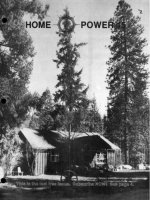
David Palumbo stands before his
PV powered home and business.
Twenty-four PV modules are
mounted on rooftop trackers.
Photo by Jay Kennedy
Sam Coleman
Paul Cunningham
John D'Angelo
Jeff Damm
Windy Dankoff
Dave Doty
Laura Flett
Chris Greacen
Scott Hening
Meg Hunt
Kathleen Jarschke-Schultze
Jay Kennedy
Stan Krute
Ed LaChapelle
Alex Mason
David Palumbo
George Patterson
Karen Perez
Richard Perez
John Pryor
Mick Sagrillo
Bob-O Schultze
Larry Todd
John Wiles
Issue Printing by
Valley Web, Medford, OR
Home Power Magazine is a division of
Electron Connection Ltd. While we
strive for clarity and accuracy, we
assume no responsibility or liability for
the usage of this information.
Copyright © 1990 by Electron
Connection Ltd., POB 442, Medford,
OR 97501.
All rights reserved. Contents may not
be reprinted or otherwise reproduced
without written permission .
3
THE HANDS-ON JOURNAL OF HOME-MADE POWER
Access
Home Power #17 • June/July 1990
4
Home Power #17 • June/July 1990
Support HP Advertisers!
ALTERNATIVE ENERGY ENGINEERING
AD
FULL PAGE
5
Home Power #17 • June/July 1990
Our village life would stagnate if it were not for the
unexplored forests and meadows which surround it.
We need the tonic of wildness to wade sometimes
in marshes where the bittern and the meadow-hen
lurk, and hear the booming of the snipe; to smell the
whispering sedge where only some wilder and more
solitary fowl builds her nest, and the mink crawls
with its belly close to the ground.
At the same time that we are earnest to explore and
learn all things, we require that all things be
mysterious and unexplorable, that land and sea be
infinitely wild, unsurveyed and unfathomed by us
because unfathomable.
We can never have enough of Nature.
We must be refreshed by the sight of inexhaustible
vigor, vast and Titanic features, the seacoast with
its wrecks, the wilderness with its living and
decaying trees, the thundercloud, and the rain
which lasts three weeks and produces freshets.
We need to witness our own limits transgressed,
and some life pasturing freely where we never
wander.
From Us To YOU
Thoreau Selections
Home Power Magazine is so much fun to be a part
of.
We and you are surfing a major positive wave of
human history: the inexorable swell of
Empowerment.
And we get to do so during the exciting late 20th
century, while that lofty surge crests and builds on
the loving labors of so many beloved ancient and
current souls. We are in the tube, stokers, with
walls all glasseous.
How do we read the state of the wave ? Well, all
you readers can just watch the magazine. The
increase in number and sophistication of the
advertisers, the ads, the writers, and the articles.
Me, I get a special viewpoint by virtue of being the
letter column pinhead. The HP mail I consider to be
the prime pulsebeat of this home power revolution.
And how is the mail ? Just GREAT. We could
publish a whole issue of nothing but letters from
excited empowered readers. And, now that we
charge $$$, we're even getting constructive loving
criticism. Signs of vigorous dynamic health.
Empowerment: We pass on to you what we have
learned, knowing you shall further its journey.
Building change steadily, inexorably, via a broad
base of distributed connected intelligence and
heart.
Power has often been closely held. We who are its
democraticians offer it to all interested parties.
Power to the people. Home-based, of course.
SK
A Note On Subscriptions & Back Issues
Several readers have asked us to begin their
subscriptions with a back issue. We are
unfortunately unable to do so, and thought we'd
explain why.
It's ruthlessly simple. When a magazine goes out
as part of our normal print-and-mail routine, the
costs are enough under $1 that we can stay in
business charging that amount per issue. When a
magazine goes out as a back issue, special
handling and first class mailing costs jack us up to
well over $1. We can stay in business charging $2
per back issue. But no less.
So, if you want to get all issues, just include
money for back issues with your subscription. And
thanks for understanding. And for the subs and
back issue orders.
KP
EMPOWERMENT
We Can Never Have Enough Of Nature
Selections from the Spring section of Walden
Henry David Thoreau
From Us to YOU
6
Home Power #17 • June/July 1990
Systems
Independent Power & Light!
David Palumbo
hen we decided to make our home in the beautiful Green Mountains of northern Vermont, we had
no idea where this new adventure would take us. Looking back at our decision of six years ago
to produce our own electricity for our new homesite, I am amazed at how this one choice had
such a profound effect on our lives.
W
The Palumbo Family
Our family is comprised of my wife Mary Val, our son
Forrest (four years old), our daughter Kiah (two years),
our latest addition Coretta (ten months), and myself.
Mary Val and I purchased land in Hyde Park, Vermont
during the summer of 1984. At this time that we began
researching the alternatives to paying the local utility
$6,000 to connect us to their line one-half mile away.
We were encouraged by friends who produced their
own power and a visit to Peter Talmage's home in
Kennebunkport, Maine. We decided to "take the road
less traveled, and that has make all the difference" as
Robert Frost (a Vermonter) put it so well. Talmage
Engineering supplied the majority of the hardware, and
Peter answered my questions. We now use alternative
energy at all three of our buildings. Let's look at each in
turn, as they occurred in time.
The Cherry House System
In the spring of 1985, while living out of a tent, we built
what we call the "Cherry House". This is first of three
buildings designed by M.B. Cushman Design of Stowe,
Vermont. The Cherry House is a two-story saltbox with
950 square feet of living space, heated by a small wood
stove. Power for constructing the Cherry House was
supplied by a Winco 4,000 Watt, slow speed,
engine/generator that runs on propane. Energy
consumption for the completed house was estimated at
1,300 Watt-hours per day. As our primary power source
we purchased ten Solenergy 30 Watt PV panels that
were on the market as seconds in early 1985. The
array was cost efficient, but not really large enough to
satisfy our growing power needs. Our battery bank, for
the Cherry House, consists of eight Surette T-12-140
deep cycle lead-acid batteries totaling 1,120
Ampere-hours at 12 Volts. Our loads for this house
included our Dometic 12 VDC refrigerator/freezer
(seven cubic feet). We added rigid insulation to reduce
the Dometic's power consumption to 420 Watt-hours per
day. Other loads in the Cherry House include a variety
of REC Thin Lite DC fluorescents and a 10 inch Zenith
color TV set consuming 4.5 Amperes at 12 Volts. When
our children began arriving, we added a washing
machine and a clothes dryer. The washer and dryer are
powered by the Winco generator through the automatic
transfer switch built into our Trace 1512 inverter/charger.
The transfer switch and charger in the Trace inverter
allow us to charge our battery bank and wash the diapers at the
same time, all powered by the Winco generator.
The Trace 1512 could not handle the surges of the washing
machine. The newer model Trace 2012 will handle most washing
machines. We used the Winco propane fired generator to do the
laundry and to help our undersized PV array charge our batteries.
The generator was also essential (until we later developed our
The Palumbo Family, David, Mary Val, Kiah, Forrest, and Cory.
Photo by Jay Kennedy, Village Photographer.
7
Home Power #17 • June/July 1990
Systems
microhydro site) because we are located in one of the cloudier parts
of the country. For example, during our first November here we had
one day of full sun followed by a delightful December with three full
days of sunshine. Wow! We eventually decided to add a hydro
system, since rainfall is generally plentiful here, and our site has the
elevation differential to support the hydro.
The Barn & Shop System
During the summer of 1987 we built The Barn with three horse
stalls, a 500 square foot work shop, and plenty of storage space on
the second floor. The Barn is located 450 feet from the Cherry
House and 250 feet from the site for the Big House. The distances
between these buildings presented us with two choices for the
overall power plan. First, we could centralize a battery bank and
inverter large enough to handle all of our power needs via 115 vac.
The second choice was to have a separate battery bank in each of
the three buildings. I went with the second option because we were
building incrementally and the "whole" was only a fuzzy image in
our mind's eye early in the project. Also, I was entering a new
business, as a designer and installer of alternative power systems.
The added experience of three separate systems was desirable and
influenced my decision.
Three separate systems may not be the most efficient way to go. I
am presently working on another large remote site, with three
buildings, several miles north of our land. This installation will take
advantage of the products available today. Specifically,
NiCad batteries and a powerful inverter located in the
garage/shop serving as the power center for all three
buildings. The advantages of this approach include
saving time & money in wiring, and the ability to use a
higher battery bank voltage. This higher system voltage
allows the charge source (in this case, PVs) to be
located further from the batteries without using the more
costly, large diameter wires. For this site, I am
designing the system with a 48 Volt battery bank.
Our Barn's power system consists of four Trojan L-16W
deep-cycle, lead-acid batteries with a capacity of 700
Ampere-hours at 12 Volts. We are using the Heliotrope
PSTT 2,300 Watt inverter. This inverter has worked
well in the shop, powering all of the tools expect those
requiring 240 vac, which are sourced by the generator.
We sold the 4,000 Watt Winco and replaced it with a
Winco 12,500 Watt, slow speed, propane
engine/generator. We did this because our carpenter
needed to use a high powered air compressor with a six
horsepower electric motor. The other machines
powered by the generator include a large table saw, an
eight inch planer, and a six inch joiner. We wired the
big Winco so that we are able to turn it on or off from
any of the three buildings, using remote four way
switches activating the 12 Volt solenoid and starter
switch at the generator. The remainder of the electrical
loads in the Barn/Shop are all lighting. We used
Thin-Lite brand DC fluorescents throughout and are
very happy with them. Since the shop is the only
heated space in the Barn, cold weather light operation
was a must. The Thin-Lites work well in the cold. They
are efficient, for example they produce 3,150 lumens of
light from a standard 40 Watt fluorescent tube. At 78.7
Lumens per Watt, this is 25% higher than the highly
praised PL lights. The 40 Watt tubes are inexpensive,
locally available, and come in a wide variety of spectral
outputs.
The Heliotrope inverters do not contain battery chargers
(like the Trace models). We use a Silver Beauty battery
charger that charges the Trojans quite well from the
Winco. However, this battery charger must be turned
on with a timer switch as it doesn't have the
programmable features of the sophisticated charger
built-into the Trace inverter/chargers.
The Big House
We felt a traditional, New England, colonial home
design offered the features we wanted at a reasonable cost. We
were looking for a lot of space, energy efficiency, and country
charm. By using all of the space under the roof, we have been able
to build a home with 5,300 square feet of heated space. All of this
The Cherry House with ten Solenergy 30 Watt PV modules on the roof.
Photo by Jay Kennedy, Village Photographer.
8
Home Power #17 • June/July 1990
Systems
sits on a "footprint" of 2,160 square feet. The Big House has a full
basement, except under the garage, that houses the boiler room,
the battery & control room, a large play area for the kids, and the
cold, root & wine, cellars. Without cramping, we can store up to six
cords of wood in the basement to augment the wood sheds outside
the garage, which hold seven cords.
We have over 100 acres of good forest land that we are managing
for both timber production and wildlife habitat. Our woodlots have a
sustained yield of over 1 cord per acre per year to supply our
buildings with heat from this renewable resource. "Big's" heat is
produced by an Essex Multifuel boiler rated at 140,000 BTUs. We
use it as an oil burner only very occasionally, it is mostly fueled by
wood. The Essex has a ten cubic foot firebox and cycles on and off
to satisfy the thermostats in our four heating zones within the Big
House. The Essex burns by a gasification process and is 95%
efficient on wood while producing no creosote emissions. We also
get all of our domestic hot water from this 1,500 pound beast's two 6
GPM heating coils. We use about 15 cords of hardwood per year to
heat the Big House and its water. I hope to install a solar hot water
heater soon so I can take a summer vacation from loading firewood
and shoveling ashes out of the Essex.
MicroHydro
I began to think about water power after the first rainy fall of 1985,
and by 1987 we began work on our microhydro project. We built a
pond on the highest site on our property. The pond is situated on
ideal soils (heavy silt on top of glacial hardpan) for pond
construction. Our pond is kept full by below surface springs and
surface run off.
The pond's surface is 210 feet in elevation (known as head) above
our turbine. The pipeline (penstock) is buried under the pond's dam
and to a depth of four feet for its entire 1,250 foot run. The inside
diameter of the pipe is two inches. I vary the water's flow rate
depending on how much power we need, while trying to keep the
pond reasonably full. By changing the hydro's nozzle from 1/4 to
3/8 inches, I change the flow rate from 17.5 to 38 GPM.
The turbine is an Energy Systems & Design IAT-1 1/2 Induction
Generator. It was chosen for this application because of the cost of
the long wire runs going from the turbine building to the three
buildings. The induction generator makes 3 phase, high voltage ac
current, and the higher voltage requires smaller gauge wire on long
runs. The longest of these runs is 450 feet to the Cherry House. In
retrospect, I would have been better off swallowing the additional
expense of larger wires (≈$600) and going with a 24 Volt DC high
output alternator, instead of the 200+ vac induction unit.
What I have now is a more complex system because of the three
phase ac induction generator. This generator requires just the right
amount of capacitance at the generator, and it requires properly
sized transformers & rectifiers at each of the battery banks. The
biggest problem is that neither the manufacturer, nor anyone else,
could accurately specify what was needed for capacitors,
transformers, or rectifiers. This is highly site specific, and in our
system complicated because we are using the power at three
places, each with its own transformer. I finally got the system to put
out the power we needed by replacing the induction generator,
capacitors and transformers with different sizes. This setup was
determined experimentally. It was very frustrating, time consuming
and expensive.
Our hydro system is now producing 240 Watts with a 1/4 inch
nozzle installed at a net head of 203 feet; this works out to an
overall efficiency of 36%. With the 3/8 inch nozzle installed the
system produces 430 Watts at a net head of 187 feet; this is an
efficiency of 31%.
The Big House's PV Array
As you can see in the photos, putting trackers on the roof is an
interesting design feature and a challenging installation. I first got
the idea while visiting Richard Gottlieb and Carol Levin of
Sunnyside Solar near Brattleboro, Vermont. They have an 8 panel
Zomeworks tracker mounted on their garage roof. Why put the
tracker on the roof? There are three advantages for us in this
application. First, it gets the PV array way up high the top of our
arrays are 32 feet above the ground. This drastically reduced the
number of trees we had to clear to get the sun on the panels. And
second, it saves space on the ground for other things like sand
boxes and gardens. Thrid, we don't have to look our over the
trackers from our windows.
Why use trackers this far north? Usually we do not specify them
here because at our latitude (45°N.) they add only ≈6% to the PV
power production during the winter and ≈22% of the year. The
reason we went with the Zomeworks Track Racks is because we
have a hybrid system. I sized the PV arrays to meet all of charging
needs during the summer. Our summer is a dry time and our hydro
system cannot be relied on then. The trackers add ≈33% to the
PVs' power production during the summer. Therefore, I reduced
the total number of panels from 32 to 24 by using the trackers. The
cost of the trackers was offset by the reduced cost of the downsized
PV arrays.
PV Installation
Each of the two arrays above our garage roof holds 12 Kyocera 48
Watt PV modules for a total of 1,152 peak Watts of solar produced
power. Over the year our Kyocera panels have consistently
outperformed their manufacturer's ratings. On a recent April day, I
observed an array current of 42 Amps at 28 VDC. This occurred
on a day when the sky had many puffy, white clouds (known as
cloud enhancement). On a clear sky, typically I measure 37.7
Amperes charging our 24 VDC battery bank. I have an analog
ammeter installed in the cover of the fused PV disconnect for quick
The Big House during the winter with David standing out
front. Note the twenty-four Kyocera PV modules on two,
roof-mounted Zomeworks trackers.
Photo by Jay Kennedy, Village Photographer.
9
Home Power #17 • June/July 1990
Systems
checks. For more accuracy, I use the millivolt scale on my Fluke 23
multimeter to measure the voltage drop across the precision
(0.25%) 50 millivolt shunt on our Thomson & Howe Ampere-hour
meter (see HP#11, "Things that Work!" article). A 48 Watt Kyocera
panel is rated at 2.89 Amperes, but I measure 3.14 Amperes per
panel.
The 24 Kyocera J-48 modules are mounted on two Zomeworks
pole-mounted Track Racks. Each tracker was placed on its pipe
mast by a crane operated by an expert and a crew of three helpers
on the roof. Hiring the crane cost $210 and was worth that and
more. Installation in any other fashion would have been asking for
trouble- possibly fatal damage to the PV/Trackers and/or potential
injury to yours truly and my crew.
The pipe masts themselves are 5 inch schedule 40 steel, each 17
feet long. The masts were cut seven feet from the base and later
spliced with a four foot section of 4 inch pipe inside the 5 inch pipes.
The splice was necessary because the full 17 feet length would not
fit into my shop easily nor would it push up through the roof easily.
The lower section of the mast (7 ft.) had a 18 inch by 18 inch plate
of 1/2 inch steel welded on its bottom. The steel plate was drilled
out for 3 one-half inch lag bolts along each side. The masts were
bolted down with eight bolts per mast. The lag bolts went through
the 3/4 inch tongue & groove plywood decking and into the 2X10
floor joists and added box bridging. The upper section of the mast
(10 feet) was lowered through the hole in the roof by two men to a
third man guiding it into the splice insert. A standard roof flange of
aluminum and rubber was then placed over the top of the pipe mast
and seated onto the roof where it sits under the high shingles and
over the low shingles. The seam where the roof flange and pipe
meet is sealed with a type of butyl tape called Miracle Seal. This
thick, pliable tape expands and contracts with the steel pipe during
changes in temperature.
The last detail of the mast's installation was fastening the pipe to
the roof rafter for stability. Absolute rigidity is as important here as
it is at the base plate. Consult with a local building expert or
structural engineer if there is any doubt about your roof mounted
tracker. We placed the masts right next to a 2X12 roof rafter,
added shims there to tighten this union, and then securely bolted
the pipe to the rafter with a large steel U bolt. With the pipe
fastened securely at its base and at ten feet (leaving seven feet
above the roof), we met the Zomeworks installation requirement
that half of the mast be buried in concrete below grade. I have
witnessed wind gusts of over 55 MPH make the arrays flutter from
side to side (buffered by the shock absorbers on the trackers), but
the same gusts do not move the pipe masts at all.
We drilled a small weep hole at the very bottom of the pipes to drain
condensation and prevent rusting from inside. The pipe masts were
grounded for lightning protection with #4 bare copper wire at the
base plates. The ground wires were bonded together with a split
bolt connector. to a common wire which ended in an eight foot
driven ground rod bonded to the main system ground.
The arrays were mounted on their trackers in our garage and wired
in series and parallel for 24 Volt operation. Module
interconnections were made with #10 sunlight resistant, 2
conductor, Chester Cable terminated in a junction box on each
tracker. Once the arrays were in place, we came out of each
junction box with #8 ga. Chester Cable. We clamped the cable to
the tracker for strain relief and fed it down through a hole tapped on
the top of the Track Rack's pipe fitting. A weatherproof connector
was used here. Of course, a loop of cable was used as slack
before entering the pipe, to be taken up during the tracker's
movement over the course of the day. The cable was then fished
out of the pipe via another hole tapped at ceiling height and a
Romex connector was used here. The two cables were run to the
center of the room where a junction box fed with #0 ga. copper
cable awaited them. The length of each #8 ga. cable is 26 feet.
The length of the #0 ga. copper cable run from the junction box,
back through the house, and down to the battery is 90 feet.
Battery Bank and Big House Loads
Our storage batteries at the Big House are Trojan J-185 deep-cycle,
lead-acid types. We use 14 of these 185 Ampere-hour batteries in
a 24 Volt configuration for a total of 1,295 Ampere-hours (31
kiloWatt-hours) of storage. In our system they are an economical
choice because we normally do not cycle them below 50% of
capacity. The Big House receives 4.8 kWh per day from the hydro
when the 1/4 inch nozzle is being used, and 8 kWh per day with the
3/8 inch nozzle. The hydro power is often switched off at the Big
House when the sun is shining, and all the power goes to the Barn
and the Cherry House. The PV panels produced an average of 3.9
kWh per day as measured during March and April of 1990 by the
Using a crane to install the trackers with PV modules already
attached and wired. Photo by Jay Kennedy, Village Photographer.
10
Home Power #17 • June/July 1990
Systems
T&H Amp-hour accumulator.
Voltage is controlled at all three of our battery banks by Enermaxer
shunt regulators. I chose the Enermaxer because all of our battery
banks are charged by multiple sources. The Cherry House is
charged by PVs, hydro and an engine/generator. The Big House is
also charged by these three sources, while the Barn is charged by
hydro and engine/generator. The Enermaxer is connected to the
battery bank and to shunt loads. It doesn't matter what the charging
sources are as long as the current rating of the shunt loads are
equivalent to the highest possible amperage of all charging sources
combined at that particular battery. The Enermaxer works well
because it smoothly tapers the voltage of the batteries to optimum
float voltage (user adjustable to a tenth of a volt).
We average about 4.8 kWh per day of power consumption in the
Big House, with 6 kWh peak during a busy, winter-time wash day.
We are able to satisfy our power requirements and keep our battery
bank quite full without using the generator because of our hybrid
PV/microhydro system.
The loads in the Big House
(14 rooms plus a full
basement) are typical for a
busy family of five. Various
lighting products (all DC) have
been used with good results
including LEDs for night
lights. During our long
winters, we average around
140 Ampere-hours or 3,360
Watt-hours used on lighting
per day. Other 24 VDC loads
include a Sun Frost R-19 (19
cu. ft. refrigerator) and a Sun
Frost F-10 (10 cu. ft. freezer).
I recently recorded their
individual power consumption
on my portable T&H
Amp-hour meter over a test
period of 3 days averaging a
room temperature of 70°F.
David Palumbo in the power room of the Big House.
Photo by Jay Kennedy, Village Photographer.
COST ITEM
$22,400 Wire, cables, conduit, fuses, breakers, distribution panels, disconnects, boxes, fans, & all labor
$5,600 Cherry House System- including generator, refirgerator, lighting, all wiring and labor.
$4,500 Winco 12,500 Watt Generator setup.
$4,377 Microhydro System- includes everything except building the pond and turbine shed
$3,700 Barn System- everything included
Big House System Specifics
$9,500 Tracked PV Arrays- 24 @ Kyocera J48 Modules, 2 @ Zomeworks Trackers, installation, etc.
$3,800 Sun Frost R-19 Refrigerator and Sun Frost F-10 Freezer
$3,125 DC Lighting- high efficiency 24 VDC fluorescent lighting
$2,250 Battery Bank- 14 @ Trojan J-185 lead-acid batteries
$1,650 Trace 2024 Inverter with battery charger, turbo, & remote metering
$695 Controls and Instrumentation
$61,597 GRAND TOTAL OF ALL THREE SYSTEMS INCLUDING INTERCONNECTION
The R-19 used 23 Ampere-hours (552 Watt-hours) per day. The
F-10 used 28.65 Ampere-hours (688 Watt-hours) per day.
Our 120 vac loads include a washing machine (350 Watt-hours per
use), a clothes dryer (propane fired with electric motor- 150
Watt-hours per use), an automatic dishwasher (275 Watt-hours per
use), a stereo system, a 19 inch color TV that uses 80 Watts with
the VCR (65 Watts alone), the controls on the Essex boiler (40
Watts), and other appliances/tools. Our total average 120 vac
power consumption per day has been running around 2.5 kWh per
day.
The inverter we are using is the Trace 2024 with stand-by battery
charger, turbo cooling fan and remote digital metering. It is able to
handle the washer, dryer, and dishwasher all at the same time. We
do the laundry during the sunny days whenever possible because
the batteries are full by the afternoon and the Enermaxer would just
be shunting off the power surplus. A better use of the sun's energy
is cleaning our 14 loads of laundry per week!
The Big House has more than satisfied our goals for an energy
efficient, comfortable, and versatile home for our family and my
growing alternative energy business. It has helped bring alternative
energy into the mainstream in our area. Our home power system is
a demonstration for those considering alternative energy as their
power source. It is also an example for bankers who are hesitant
about lending on non-grid connected property. We have been able
to open some eyes and get a few projects going that would
otherwise never left the drawing board.
I wish to thank those contributors I have already mentioned. Also
all the fine people who worked on the project, most notably, Gary
Cole (Electrician), George Stone (Carpenter), and David Vissering
(Jack of All Trades).
Total System Costs
The below total includes all of the excavation, conduit, and wiring
used for the underground burials between the three buildings.
Access
David Palumbo operates as Independent Power & Light, RR#1,
Box 3054, Hyde Park, VT 05655 • 802-888-7194.
11
Home Power #17 • June/July 1990
TRACE AD
ENERGY DEPOT AD
INDEPENDENT
POWER & LIGHT
PV & Micro-Hydro Systems
Professional Design Work & Sales
Personalized Service
Code Installations
Summer Special
Site Evaluation and System
Design $95 (will be credited
against pruchase of system).
Travel time and expenses will be
extra.
RR1, BOX 3054
HYDE PARK, VERMONT 05665
phone# (802) 888-7194
12
Home Power #17 • June/July 1990
KYOCERA
AD
ZOMEWORKS
AD
IMPORTANT PRODUCT UPDATE
Heliotrope General has just announced the major
redesign of the CC-60 charge controller. The
updated model, the CC-60B has three major
changes. 1) A higher state of charge voltage
range which now allows charging of NI-CAD
batteries. 2) Test output jack which allows
measurement of panel voltage, battery voltage
and PV charge current rate in Amps. All of these
measurements can be made with a voltmeter.
3) LOW VOLTAGE DISCONNECT option is now
available. The selectable low voltage disconnect
is designed to protect your battery bank from
harmful and permanent discharge.
For more information contact:
Barry Brunyè or Ken Seiber
Heliotrope General
3733 Kenora Drive
Spring Valley CA 92077
800/552-8838 (in CA)
800/854-2674 (outside CA)
SOLAR ENERGY RESOURCES CO.
You can build your own S.P.O.T.
Stationary Position Optical Tracker
Solar Heating System
Special Materials Kits Available
• Thousands in use
• No Adjustments Ever!
• Highly Efficient - Well Proven
• Easy - Quick - Low Cost
• Aesthetically Pleasing
• Very User Friendly
• Easy Weekend Project
Installer's Manual - $6.00
Plans (including manual) - $15.00
Foreign add - $4.00
Plans not sold without Manual
Solar Energy Resources Co.
POB 308
Youngtown, AZ 85363
US PAT. 4003366
NOW!
13
Home Power #17 • June/July 1990
Systems
Northern Sun Power
Ed LaChapelle and Meg Hunt
e were a long way out in the Alaskan bush, over 100 miles from the nearest power grid, and
spending more & more time in a two-room log cabin while planning our bigger homestead. The
little cabin worked on dry cell batteries for a radio, and kerosene lamps. The latter were a fire
hazard and would never do on a larger scale. Photovoltaics were the obvious way to go, but we had to
start from scratch on the design.
W
Seasonal Swings
At 61°28' N., the seasonal swings in power demand just for lighting
would be huge. No solar insolation data for the area were available.
Climate data and our own experience told us that prolonged periods
of completely clear weather were limited, occurring mostly in the
spring and fall. "Partly cloudy" was the most common sky
description, often meaning cloudy part of the day, broken clouds,
thin clouds, or clouds over part of the sky. None of these allows
clear prediction of power output from solar panels. Our power
requirements were also fuzzy, except that we knew they would
probably increase as our bush lifestyle developed. All of these
factors combined to make us go light on theory and heavy on
empirical observations and hard experience.
High in the Alaskan Mountians, photovoltaics provide electrical power far from commercial utilities and power lines. In the
background is the Wrangell Mtn range and Fireweed Mountain. In the foreground, Kyocera J48 PVs make the power.
Photo by Ed LaChapelle.
14
Home Power #17 • June/July 1990
Systems
Gathering Data
So we started out small. For the little cabin we had one Kyocera
J-48 PV panel, one 200 Ampere-hour battery (used, from a fishing
boat), one PL-13 lamp, a radio and a homebrew manual controller
with a good ammeter. A car stereo outfit was added later. We
started a regular program of logging panel output throughout the
day in a variety of sky conditions. We experimented with panel
location, angle and effect of tracking (by hand). When we were
away for a couple of months our neighbors down valley, Kirk and
Lisa Olsen-Gordon, also solar energy enthusiasts, took over the
panel, controller and observations. They gathered many additional
numbers for our growing tabulation of available sun power here in
the mountains of south-central Alaska.
In the meantime we acquired and remodeled a much larger log
cabin nearby. This was going to be our solar-powered homestead.
By this time, we had accumulated enough of that hard earned
experience to start projecting our power needs and figuring out what
would be required to meet them. We took to heart a guiding
principle of home power and started first on power conservation and
load management.
Conservation
The best way to practice conservation is to unplug it altogether.
Among other things, Meg found a good hand-powered coffee mill
and an iron that could be heated on the stove top. She also
retrofitted her sewing machine with a treadle, finding it more fun &
powerful; besides it doesn't generate radio interference. We
determined to use PL lamps, which combine good light qualities of
incandescents with the power savings of fluorescents., We also
knew that we needed to get more natural light into the typically dark
log cabin so that we wouldn't use the lamps in the first place.
Skylights
The obvious way to get more light into a log cabin is through
skylights. This can be a problem in snow country. The problem is
not so much the considerable weight of the snow but what it does
when it starts creeping and sliding. A skylight that sticks up from
the surface of the roof is in for trouble. Fortunately, I devised a way
to build skylights flush with the surface of the steel roofing. We
0.0
0.5
1.0
1.5
2.0
2.5
3.0
7:00 8:00 9:00 10:00 11:00 12:00 13:00 14:00 15:00 16:00 17:00 18:00 19:00
Single Kyocera J48 PV Amperage Output
June 20-21, 1989 Wrangell Mountains, Alaska.
61° 26' N. Latitude
Hour of the Day (Daylight Savings Time)
have two 2 ft. x 2 ft. and one 1 ft. x 2 ft. skylights. These, along with
existing windows, white panels in the ceiling and a pine floor give us
enough light to go lampless from wakeup to after supper from
March to October.
Constraints
Our site included a couple of constraints on our solar energy use.
One was a surrounding small forest of poplars, the ubiquitous
Alaskan weed tree. Fortunately our plans included adding a second
storey library space to a separate shop building. A platform on the
roof offered an ideal solar panel location, although it meant running
about 75 ft. of cable to the batteries. Good solar access more than
compensated for cable losses, figured to average around 5-7%.
The other constraint was cold batteries. The logical battery location
was in an existing cellar underneath the cabin,
but in these latitudes not far south of the
permafrost zone, the mean annual ground
temperature is not far above freezing. The cellar
gets well below freezing in winter and creeps up
to about 45°F. by late summer. It makes a great
refrigerator, but is not a happy place for lead-acid
batteries. But it was the only place for the
batteries to protect them from winter
temperatures down to -60°F., which the cabin will
cool to when left unheated. Our system design
had to allow for loss of battery capacity, plus run
a resistance heater in the battery compartment to
compensate for temperature by using surplus
power diverted from the PV array.
Final Design
Our final design included eight Kyocera J-48
photovoltaic panels, four Trojan L-16 batteries, a
Trace 1512 inverter/charger and a pair of Trace
C-30 controllers. This is pretty much a
conventional package, but the whole system is
hooked up in an unconventional fashion to solve
some anticipated problems. A pair of controllers
was the result.
Help
Early in the planning stage, I visited the Trace Engineering factory
in Arlington, WA. I garnered much useful information from the
helpful folks there. Mike Frost, Trace's design engineer, pointed out
that when large loads are switched on and off the inverter, there are
wide swings in the battery's voltage that could cause trouble for 12
volt electronics on the same battery. This set in motion the design
of a split system to operate 12 volt circuits and the inverter from
separate battery banks., This system has several advantages. For
one thing, it is redundant, offering built-in back-up power in case
something breaks down. It also becomes very flexible if provision is
made to switch solar panels between the two parallel
controller-battery circuits.
The Split-System Control
The heart of our photovoltaic system is a dual-channel controller
built around two Trace C-30 PC boards. These boards have been
modified by replacing the single pole single throw (SPST) relay with
a physically identical relay with single pole double throw (SPDT)
contact configuration. This allows the use of diversion power from
the array. The A-channel (12 Volt circuits) switches diversion
power through a separate controller (Trace C-30A) to charge
auxiliary batteries, including a neighbor's hooked up through a set
of jumper cables on the cabin's outside. The B-channel (inverter)
feeds diversion power to the battery heater. Two solar panels are
15
Home Power #17 • June/July 1990
Systems
permanently connected to the A-channel, two to the B-channel. The
remaining four panels can be assigned to either channel through
bistable impulse relays located in a junction box next to the solar
panel array. These relays are controlled by momentary-close
switches located on the controller along with LED status indicators
for the switchable panels.
Engine/Generator Backup
When the sun appears only an hour or two a day around the winter
solstice and cloudy weather is common, recharging the batteries
with an auxiliary generator is essential. In choosing a generator we
took careful heed of the fine print in the inverter manual warning
about the importance of keeping up ac peak voltage to insure
high-rate battery charging. The Onan 3.0 RV has proven very
satisfactory in this respect, for it delivers full power even under
heavy loads. It is a compact, 3600 rpm model with high-volume
axial flow cooling. Located inside the shop space, its blast of hot air
can serve as a useful auxiliary heat source. So far, under our
present energy demands, we have not needed to use the generator
at all from late February until mid-October; the solar panels do it all.
Further, owing to the wonderful performance of our Trace 1512, we
never have to use the generator to run power tools.
Array Angles
The solar panel array faces due south and has provision for
seasonal adjustment of tilt angle. In winter mode, the array is tilted
up 72° from horizontal, in summer mode, 48°. The angle is
changed around the spring and fall equinoxes. Although some solar
energy users at these latitudes simply hang their PV panels on the
vertical south wall of buildings, we found that this is quite inefficient
on cloudy days. Overall power production is optimum when the
panels are tilted back far enough to allow exposure to bright clouds
instead of dull trees, eventhough the panel angle may at times be a
bit off from perpendicular to direct sun.
Left: Untroubled by a spring thaw, Meg prepares the solar-powered freezer for food storage. Increasing the insulation on this
freezer reduced its power consumption to half. Center: The exterior of the split-system charge controller with metering.
Left: An interior view of the same charge controller. Photos by Ed LaChapelle.
LaChapelle & Hunt Power Consumption
Watt-hours Watt-hours
ITEM per DAY per WEEK
Freezer 357 2500
Lighting (PL-13 Fluorescents) 100 700
Electronic Typewriter 57 400
AM Receiver & Amplified Antenna 29 200
Short-wave Receiver & Weather Fax 25 175
Power Tools 21 150
Stereo 14 100
Appliances 14 100
TOTALS 618 4325
0
100
200
300
400
W
a
t
t
h
r
s
/
d
a
y
Where the electricity goes…
16
Home Power #17 • June/July 1990
Systems
The town of McCarthy, Alaska. Once a big copper mining town, McCarthy now has about sixty residents in the summer and
about ten hardy souls in the winter. If you have electricity in McCarthy, then you make it yourself. Photo by Ed LaChapelle.
Luxury
The installation was completed in the summer of 1987. Since then
we have enjoyed the luxury of all the power we need, not only the
practical benefits but also the sense of satisfaction from generating
silent, pollution-free electricity. In 1989 we added a 12 volt freezer,
the only major increment so far in our power consumption. As
received from the manufacturer, this freezer was woefully under
insulated and inefficient. We covered the body with an extra two
inches of blue foam insulation. Then we installed it on the north
side of the cabin, where it is well shaded and the condenser coil can
draw cold air by convection from a crawl space underneath the
cabin. This brought about a notable improvement in efficiency, with
the duty cycle now ranging from around 35% down to 15% as mean
daily temperature drops from 60°'s down to the 30°'s.
Problems
Our only problems have been cold batteries and radio interference.
Even with the battery heater and insulation keeping the batteries
about 10° above cellar temperature, the derated capacity still leaves
little margin for extra power storage. This problem is compounded
by the lack of provision for a finishing charge in the C-30 controllers.
Thanks to the dual channel system with switchable panels, we can
compensate in part my manually reducing charge rates to top off the
Solar System Material Cost
ITEM COST
8 @ Kyocera J-48 PV Modules $2,232
Onan 3.0RV Generator $1,590
Trace 1512 inverter/charger/DMM $1,310
4 @ Trojan L-16 Batteries & 4/0 Cables $550
Cables, Relays, & Junction Boxes $400
Controller Parts $368
TOTAL $6,450
batteries. In fact, we have come to believe that the ideal controller
would achieve a tapering charge by successively disconnecting
panels from the array, rather than trying to taper the full array
current by pulse-width modulation.
Planned Improvement
Our next system improvement, scheduled for the summer of 1990,
is to put in pocket-plate ni-cad batteries on the A-channel (12 volt
circuits) and place all four L-16's on the B-channel (inverter and
freezer). Again, the flexibility of the dual system comes in handy,
for we can add ni-cads for part of the power storage without having
17
Home Power #17 • June/July 1990
Systems
to dump the lead-acid batteries and replace the whole works.
Radio Interference
Fighting radio interference from a PV system with an inverter is a
whole story in itself. The problem is a critical one for us here. Our
main radio reception depends on weak, remote fringe area signals
from AM stations on the other side of some very big mountain ranges.
Extensive shielding and filtering help. Isolating the radio power
supplies to separate, auxiliary batteries helps even more. The inverter
generates interference even in standby mode, so this is never used.
A pushbutton and solenoid allow remote control of the inverter in the
cellar, so we can turn it on only when ac power is actually required.
We're still working on these RFI problems and are keen to exchange
information with other Home Power readers.
Happy to Report
We're happy to report that home power is very much alive and well in
our part of the world. Most households we know have or plan to
acquire at least one or two panels. Some have systems as large as
ours, some even larger. The National Park Service is presently
installing a full PV system to power a ranger station across the
mountains to the north of us. Owing to the low solar power available
in mid-winter in these latitudes, gasoline or diesel auxiliary generators
are common, as well as reliance on propane for lighting. Micro-hydro
is getting some local attention these days and we know of one case in
which full-time diesel generation has been passed up in favor of
part-time generation to charge a battery-inverter system. In the next
few years expect to see Alaska become a leader in modern alternative
energy systems.
Access
Ed LaChapelle and Meg Hunt, POB 92723, Anchorage, AK 99509
Meg &Ed enjoy the views from their second storey solar
deck. The deck also serves for sunbathing & aurora-viewing.
Photo by Ed LaChapell and the autotimer.
Pacific West Supply Co.
16643 SW Roosevelt
Lake Oswego, OR 97035
(503) 835-1212 • FAX (503) 835-8901
Pacific
West
Supply Co.
+
_
A Resource Holdings Ltd. Co.
✓ 100% Cycling Acceptable
✓ No Sulfation or Memory
✓ Low Maintenance
✓ High Quality, Long Life
✓ 30+ Ampere-hour sizes
✓ New or Reconditioned
✓ Call for availability & sizes
Nickel Cadmium Batteries
Things that Work!
Tested by Home Power
"The best battery for your home power needs!"
18
Home Power #17 • June/July 1990
Support HP Advertisers!
Electron Connection Ltd. welcomes Bob-O Schultze to the Crew as Systems Manager.
And Bob-O is really HOT! Check out these great deals from Electron Connection!
KYOCERA J48 PV MODULES
48+Watts • 16.7 VDC •2.87+Amps. List Price is $335.
Bob-O's
salute
summer
sun silicon
solar cell
sale:
1 for
$
300.
2 for
$
590.
4 for
$
1,150.
UPS Shipping FREE inside Continental USA
The Finest Kind for Home Power Systems.
NOT Used, NOT Recycled, NOT Pullouts.
These are factory fresh polycrystalline modules. Kyocera's
warranty is the longest in the industry- TWELVE FULL YEARS.
Your panels are a lifetime investment! Don't settle for less than the Best! You're worth it!
Power Star POW 200 Inverter
12 Volts to 120 vac up to 200 Watts (140 Watts continuous). List Price -$149.95
Bob-0's get it up and running price-
$129.00
19
Home Power #17 • June/July 1990
Education
"Hands-On" Solar Power
the CMC Energy Efficient Building Students 1989/90
he Colorado Mountain College (CMC) Energy Efficient Building Technology Program teaches the
design and installation of solar and energy efficient building systems. Participants receive two
semesters of hands-on building construction experience. This article, written by the class, details
our recent state-of-the-art passive solar remodel. Client and class member, John D'Angelo volunteered
his mobile home for the project. He purchased a trailer with solar retrofit potential. Four different solar
systems were designed: 1) a larger window for direct gain heating and a better view; 2) a solar hot air
collector; 3) a passive domestic solar hot water heater; and 4) a solar heated natural gas generator.
T
But First, INSULATE!
Comprehensive weatherization is a pre-requisite for solar space
heating. Air leakage reduction (stopping drafts) should always
precede "supply side" thinking. Caulking, insulation, storm
windows, skirting, etc. are cost effective pre-solar heating
procedures. John took advantage of his student status and
qualified for the local energy center weatherization program. Now
the solar power will work efficiently and help heat the trailer into the
evening hours. It doesn't make sense to collect free solar heat if
you allow it to leak out as fast as it comes in. Also, efficient
domestic hot water strategies should always proceed any solar hot
water heater. Quality low-flow shower heads, low flow plumbing
fixtures and pipe insulation should always come first.
To complete John's solar retrofit he designed a solar powered
natural gas generator. He dislikes cooking with electric (frustrating
heat control and incompatible with his future PV system) and
decided to produce "home grown" natural gas.
Site Preparation
We choose to build a permanent complete foundation system to
support the heavy collectors.
The exterior of John DAngelo's trailer showing left to
right, the methane digester,the solar hot water heater,
and the fan assisted hot air collector. Above them, the
passive solar window heats the trailer. On the roof, a
photovoltaic panel provides electric power to run the
active hot air system.
This trailer is located in the Colorado mountains, and
even here solar energy can be cheaply and effectively
used.
Photos by the CMC Crew.
A drawing of the solar systems on John's trailer.
20
Home Power #17 • June/July 1990
Education
"It's called concrete - not cement," reminded CMC instructors to the
CMC class of 1990. Cement is just one ingredient in concrete.
The pour was small, 8' x 10', well planned and much work. We
used a transit to establish proper elevation and excavated a
rectangular slab. A plywood form with reinforced corners was built
with drywall screws and cross-taped to establish square corners.
The sill plate was attached directly to the inside of the form and
anchor bolts were countersunk into the sill plate every few feet.
Either pressure treated lumber or redwood can be used. By
attaching the sill plate to the form before the concrete was poured, a
nailing surface for the wall plate was permanently in place. This
enabled us to easily screed the
concrete level. The thickened edge
slab perimeter was reinforced with #
4-1/2" rebar that was lapped and tied
together to the dangling countersunk
anchor bolts. Dirt was temporarily
backfilled against the form and we
were ready for the concrete.
The pour was short. We moved lots
of concrete quickly. The concrete is
rated at 4000 p.s.i. and reinforced
with plastic fibers. By adding these
fibers to the mix, we could eliminate
the standard reinforcing 6" x 6"
remesh.
There are many techniques for
finishing concrete and I think we
practiced nearly all of them. We took
turns with the various floats, trowels,
and brooms and experimented with different finishing techniques.
Hours later, we covered up our work with rigid insulation to prevent
it from freezing. Concrete needs three days without freezing to cure
properly. Our slab was designed to support the weight of heavy
collectors, but this foundation system works well for attached
greenhouses and sun spaces.
Daytime Solar Heating
Daytime heating of our houses accounts for approximately one-third
of our heating bills. Solar space heating systems that have no
supplemental heat storage (like expensive rock boxes or water
barrels) can offset a good portion of the daytime heating
requirements. They are especially appropriate in living spaces
where people are home during the day. Two types of these
systems that we installed on this trailer are called Direct Gain (DG)
and Fan-assisted Air Panel (FAPS).
Direct Gain Systems
Direct Gain Systems use a window to allow the sun's heat into the
house and some form of movable insulation (MI) to keep the heat in
at night. The window or glazing is best at a vertical position to allow
the low winter sun to penetrate. Effective movable insulation
prevents nighttime heat loss and should have an edge seal, high R
(insulation) value, a radiant barrier, and a vapor barrier. Simple MI
can be a removable piece of rigid insulation cut to the exact size of
the window. Thick homemade drapes with velcro on the edges will
help keep the "building envelope" tight and warm. It is important to
design DG systems to avoid overheating during the sunny winter
days. In Colorado, we recommend the window area be no more
that 15% of the heated floor area. "Too much of a good thing" like
south facing windows often create uncomfortably hot and glary
living areas. The size window we installed on John's trailer can
effectively heat only half the trailer.
The window should be facing within 30 degrees of true south- the
optimum range of orientation for all solar collectors. Facing east or
west by 30 degrees only effects year round efficiency by 10%. East
facing windows can provide early morning warm-up, but west facing
windows often cause overheating in the spring, fall, and summer. A
limiting factor of DG systems is that they are only appropriate for
rooms with walls facing close to south.
Fan-assisted Air Panels
To solar heat north facing rooms, Fan-assisted Air Panels (FAPS)
are a good strategy.
2" x 4" redwood sill plate
1/2"
Plywood
Recessed
8" anchor bolt
Concrete
4" slab
Temporary
backfill
Undisturbed Soil
Blower Box
Cool Air Supply
Warm Air Return
F.A.P.
Insulated Duct
South
The duct work, and a small solar electric blower move the air
through a closed loop between the house and the collector. House
air is pulled from a return grill in the north bedroom floor, through
duct work, into the blower box and then pushed into the solar
collector. A very short hot air supply duct (to minimize heat loss)
supplies the warm air back into the house. The temperature of the
air entering the house is 75° to 110° F. and varies with the amount
of daily solar insolation. Higher temperatures may seem desirable,
but actually very hot air lowers efficiency. It is more desirable to
have lots of warm air than a smaller volume of hotter air. Since
house air is sucked into the insulated return duct on the north side
of the house, John receives the added benefit of improved warm air
distribution. The blower on the FAP system distributes the heat
from the DG window and the wood stove to the cooler end of the
trailer.
The foundation of the solar systems on John's trailer.
A schematic of the fan assisted hot air system
21
Home Power #17 • June/July 1990
Education
Collector Tilt
In northern latitudes the rule of thumb for optimum wintertime tilt
angle is latitude plus 15 degrees. For most of North America, this
results in tilt angles of 45 to 65 degrees from horizontal. However,
we prefer to mount solar air collectors directly to the vertical south
facing wall. Ease of installation, avoidance of summertime
overheating and increased ground reflection from snow have proven
strong determinants. John's combination of solar systems and his
trailer's south wall dictated a compromise tilt angle solution. For
integrated aesthetics and simplicity we installed the air, water and
natural gas generator systems all at 45 degrees.
Air Collector Specifications
The solar air collector was designed and built by the class in our
campus workshop. Prior site inspection assured proper positioning
and duct size. As with all solar air collectors, our system consisted
of a frame, covered with a glazing and containing an absorber plate
with an insulated air channel.
The frame was built of 24 and 26 gauge paintlock sheet metal
fastened with pop-rivets and screws. All joints, seams, and
connections were sealed with pure, clear silicone caulk to prevent
air leakage. Sheet metal was chosen because it is durable,
fire-resistant and inexpensive. Wood should never be used in solar
air collectors. Despite how wood is treated, it can cause problems
by out gassing and warping. Wood frames do not remain air tight
and have charred from long-term exposure to the high temperatures
typically reached inside the collector. The collector gets extremely
hot when the blower is off. A "stagnated" collector regularly
reaches interior temperatures more than 250° F.
The total collector frame size was determined by the glass unit
dimensions. A 34" x 76" single pane of tempered, low iron,
translucent, 5/32" thick glass was supported by the entire perimeter
of the metal frame and protected with flashing. The glazing is
isolated from the metal with E.P.D.M. tape and sealed in place with
pure silicone caulk. The generous and continuous silicone bead
gives structural support for the glass unit. The advantages of glass,
versus plastic, as the glazing material are its high transmissivity and
extremely long life span. For safety, always use tempered glass
units. The standard sizes of low iron glass are 34" x 76", 34" x 96",
46" x 76", 46" x 96" and 46" x 120." Low iron "solar" glass offers
maximum solar transmissivity. These units are available in either
transparent (clear) or translucent (frosted) with solar transmittance
gain the same for both types of glass. For aesthetics, we suggest
translucent glass.
A special manufactured selective surface was our choice of material
for the absorber plate. It's high absorptivity and low emissivity
soaks up the sun's rays and doesn't re-radiate them back out the
glass. Our thin (.002") copper selective surface absorber was
pop-riveted to the sides of the frame and supported in the middle by
an air channel guide. Black, pure silicone caulk was used to seal
the seams. The criteria for designing a successful solar system
absorber are high conductivity, maximum surface area, & durability.
Insulating the back and sides of the collector improves system
performance. Only high temperature insulation is considered. We
used 3/4" polyisocyanurate rigid board insulation. To prevent an
insulation "meltdown," do not use any styrofoam insulation products.
It is important to avoid any possibility, however remote, of the
insulation out-gassing and causing air quality problems. We
completely isolated the air flow channel with sheet metal thereby
eliminating the possibility of long-term degradation that could result
in an air quality concern.
Proper selection of materials and attention to detail will insure a
high performance solar air collector. Always use non-toxic
materials that can withstand high temperatures. Caulk and re-caulk
to prevent air leakage. Pure silicone is proven to be the best when
sealing metal to metal and glass to metal.
The total cost of the project was $451.01 including duct work and
electrical parts. The solar panel was loaned to John from the CMC
program.
Solar Air System Distribution
A 6", 26 GA round duct insulated with 2 layers of foil ray, (foil
coated bubble pack duct insulation); two registers - Inlet 6" x 12",
Outlet 4"x 12"; 1 -12 volts, 5 amp shaded pole DC blower; 1 ply
wood blower box - shop built, insulated, caulked with removable
access panel.
Air System Controls
The controls of a conventional 110 volt FAP system consists of 2
thermostats. A regular heating thermostat is mounted at a central
location in the space to be heated. Another thermostat is placed in
an accessible spot within the warm air duct. The heating
thermostat is set at a desired room temperature and functions like a
normal furnace thermostat. The warm air thermostat is set to go on
at 110° F and off at 90° F. In this system two conditions have to be
met for the blower to turn on: 1) the room temperature has to drop
below a desired level, and; 2) the air inside the collector has to
reach at least 110° F. When the room reaches the set temperature
or the air inside the panel falls below 90° F. the system shuts off.
John is a solar enthusiast and decided to have a Photovoltaic (solar
electric) panel installed to power the blower.
12 V
Blower
Summer -
Winter
On - Off
Switch
PV Panel
Positive
We mounted a 12 volt - 50 watt nominal PV module on the roof of
his trailer at a 45 degree tilt. It is directly wired to the 12 volt DC
blower with an on-off switch inside the trailer. Now, the sun does
the control function. As sunlight heats the air inside the air collector,
the PV module provides electricity powering the blower. The
advantage of this system is that it works proportionally without any
complicated devices. As solar energy increases the temperature
inside the air collector, it also also increases electricity from the PV
module. Therefore as the blower speed increases more warm solar
air is blown into the trailer. Elegantly, the solar powered electricity
is proportional to the amount of heat produced by the collector, thus
making this control strategy almost ideal.
A Blower Box for the FAPS
To provide convenient installation of the electric blower for the solar
A schematic for the fan's electric system.
22
Home Power #17 • June/July 1990
Education
air system, we built a plywood plenum box.
This box simplifies duct work and maintenance procedures. The
blower blows house air into the collector, keeping the collector
under positive pressure. This prevents active cold air leakage into
the hot collector. Installing the blower in the cool air duct also
allows increased blower life by preventing motor overheating.
Passive Solar Domestic Hot Water System Design
John choose a batch solar hot water heater because it is so simple
and almost maintenance free. There are no pumps, controls,
sensors or mechanical BS. It is a black water tank inside an
insulated box. A reflective surface inside the box increases the
amount of solar energy striking the water tank. One commercially
available unit is the Cornell Model 480. It has a fiberglass box with
polyisocyanurate insulation, a steel tank wrapped with selective
surface and an enhanced multi-layered glazing. Because it is
insulated and contains a 42 gallons of water it has withstood outside
temperatures of -35° F. Pipes that go into the tank must be heavily
insulated or have electric heat tape to prevent freezing. We
recommend both for Colorado's cold winters. Do-it-yourselfers
should avoid building solar water heaters with wood or insulation
that is not heat tolerant.
The solar water heater should provide 100% of John's hot water for
eight months of the year and work as a preheater for the other four
months. One 42 gallon batch heater usually provides an adequate
amount of hot water for 2 people. For larger households, two or
more batch heaters can be hooked up in series. Typically 20% of
the total household energy goes to heat hot water. We estimate
this system will provide 60-80% of John's hot water when
supplemented with other efficiency measures such as energy
efficient shower heads.
Installation Details
We installed the collector at 45° for aesthetic reasons and to use
water's natural stratification to always obtain the warmest water
possible. With the collector oriented and tilted correctly, plumbing
began. Copper pipe (3/4" and 1/2") was used throughout. High
temperature, low lead, 95/5 solder was used to solder all joints.
A tempering valve was installed to prevent "scalding" water
temperatures from reaching faucets. It is an important safety
equipment item. Water in passive SDHW systems can easily reach
160° F on a summer day.
In John's system, four thermometers will be placed on lines going
into and out of both the solar hot water heater and the small electric
heater (17 gallon, 120 VAC electric). Knowing these temperature
differences, John can evaluate solar system performance.
Manually operated ball valves were placed at strategic points in the
system. John's plumbing enables him to have three distinct modes
of operation: solar only, preheat and auxiliary only. Please refer to
the valving schematic. All ball valves are placed close together and
labeled. The valves are easily visible and accessible under the
kitchen cabinet. Providing for convenient operation and
maintenance is part of good system design and installation.
Natural Gas Generator
The last section of the system is a natural gas generator (commonly
known as a methane digester). This unit will provide John with gas
cooking and supplementary heat during the winter time. The unit is
experimental. John made natural gas from cow manure years ago
and thought it would be exciting to do it on a home size scale.
The system has two basic units. A 65 gallon plastic tank and a gas
storage unit. The tank lies in a horizontal position inside a direct
gain solar space. There will be an inlet to load the tank with raw
materials and on outlet to remove the "dijested" material. There will
be several tubes in the top of the tank to place temperature sensors
and for thermostatic control of a small heat pad for auxiliary heat. A
natural gas meter will be placed in the line so John can collect
performance data. Gas will be generated 24 hours a day so a
plastic storage tank is necessary. John likes plastic because it can
be recycled, is not effected by methane, is easy to work with, lasts a
lifetime and is inexpensive.
To obtain the best performance, the ideal liquid temperature is
98°F. John estimates 85% of the energy required to heat the
liquid will come from direct solar gain and the balance will come
from an auxiliary heat source.
John does not know exactly how the unit will do during the cold
winter nights. In the winter he plans to use some auxiliary heat
from the 450 watt heat blanket to keep the liquid at the optimum
temperature. He is counting on the thermal mass of the liquid
and superinsulation to moderate the temperature swings. In
the summer the solar glazing will be covered most of the time
except when heat is required. He plans to have a temperature
swing of 20°F., from 100° to 80°. The closer he can maintain a
constant temperature the better his gas production. His goal is
to have natural gas year around with a minimal amount of effort
and energy. John plans to write a follow up article for HP about
the generator's performance.
Summary & Access
Fan blades
pop
top
outlet
to
Living room
intakeFan
Electrical
junction
box
Solar Hot Water
Cold Water Supply (City or
Country main Line)
42 Gallon Hot
Water Tank
Shower,
Laundry,
Dishes,
etc.
The blower box.
The solar hot water heater.
23
Home Power #17 • June/July 1990
Education
Hot
Cold
Drain
Solar Supply
Solar Return
Cold Water To
House loads
City Water
1
2
3
4
5
6
Mixed Hot Water
Valve 1 2 3 4 5 6
Solar Only
Preheat
Auxilary
Closed Open Closed Open Closed Open
Open Closed Closed
Closed ClosedOpen
Open Open Open
Open Open Closed
The project was a great "hands-on" learning
experience and fun for all. The class knows
after they were done it was another small
step toward a cleaner environment.
Many thanks and appreciation goes to those
who wrote different parts of this article and
actively participated in the project: Students:
Gary Beckwith, Marlene Brown, John
D'Angelo, Evan Lawrence, Juan Livingstone,
Zoe Shinno, Markus Stoffel, and Mark Wolf.
Instructors: Johnny Weiss and Steve
McCarney.
For further information on the Energy
Efficient Building Technology program write
Colorado Mountain College (CMC) , P.O. Box
10001PB, Glenwood Springs, CO. 81602 or
call 1-800-621-9602 in CO or
1-800-621-8559 outside CO. For any
information on the trailer project contact John
D'Angelo, 0171 Hwy 133 C-2, Carbondale,
CO or 303-963-9632.
A schematic of the
valving of the hot
water system.
The CMC Crew, clowning around after a job well-done.
August 17-19, 1990
Amherst, Wisconsin
To educate, demonstrate and promote the
efficient use of renewable energy
This fair will introduce the general public
to a wide spectrum of renewable energy
technologies and applications.
Call NOW for information
on business booths.
Workshops, demonstrations and product
promotion will expose thousands to new
ideas and products that produce or
conserve energy and protect our
environment.
Midwest Renewable Energy Fair
286 Wilson St., Amherst WI 54406
715-592-4458
See page 42 for more information & details.
24
Home Power #17 • June/July 1990
Support HP Advertisers!
BACKWOODS SOLAR ELECTRIC SYSTEMS
For an Earth Restored And A World At Peace
Independent Electric Power Systems For The Remote Home
Solar Electric, Wind, Hydro
We are a family business, living with our products for over 10 years, and
offer the knowledge to help you set up your energy system. Our catalog
includes lower than usual prices on solar modules, lights, pumps, Trace
inverters, Sun Frost refrigerators, and more. Free consultation.
Questions are personally answered.
Our own 30 amp Backwoods Charge Controller standard features: Large
amp and volt meters, trickle finishing charge, hand adjustable set voltage on
automatic charge control, battery connection cable including main fuse,
reverse current blocking diode, surplus power diversion, and manual
override switches. All one unit for easy installation. Price is $305
Send $3. for catalog/planning guide.
STEVE & ELIZABETH WILLEY
8530-HP RAPID LIGHTNING CREEK ROAD
SANDPOINT, IDAHO 83864, Ph (208) 263-4290
The biggest news in water
pumping isn't the pump.
The big news is Sun Selector LCB generation four. ™
Generation four LCB products will get more
water from your pumping system than ever
before. More water, more air flow, or
whatever your sun-synchronous power system
moves, the new LCB's will get more work out
of your system.
Our patented generation four LCB is the most
reliable, most efficient, most effective, yet
lowest cost photovoltaic/motor interface ever
sold. You'll agree when you see the results.
We're also announcing three NEW LCB's:
LCB 3m, LCB 7m, and the incredible LCB
6HVm.
These new LCB's cover almost every need
you're likely to encounter.
Call us for your factory authorized Sun Selector
distributor today.
1-800-222-3988
SUNNYSIDE
SOLAR
regional distributor for
• SOLAREX
• HOXAN
• SOVONICS
We also carry a full range of
Balance Of System
components & equipment
including
Prefabricated Systems
Ask about our wide variety of
LOW VOLTAGE
LIGHTING
SUNNYSIDE SOLAR
RD 4 Box 808 Green River Rd.
Brattleboro, VT 05301
802-257-1482 • 800-346-3230
25
Home Power #17 • June/July 1990
Water Pumping
Water Supply For The Independent Home:
Running Submersible Well Pumps On Inverter Power
Windy Dankoff
he submersible well pump is one of the great inventions of the 20th century. From domestic use to
remote livestock watering, the "SUB" has replaced all sorts of hand pumps, jack and piston pumps,
chains, buckets, windmills, etc. It is inexpensive, reliable and reasonably efficient. Millions are in
use worldwide.
T
PUMPING IN HOME POWER SYSTEMS
Homes beyond the power lines often have alternative energy
systems, usually photovoltaics with storage batteries. There are
perhaps 50,000 such homes already in the U.S. and a growing
industry to serve their special needs low voltage DC lights,
appliances, pumps and electronic inverters. An inverter converts
the stored DC power to household AC. Most independent homes
use a combination of DC and AC appliances. A variety of special
DC pumps are available. See articles in Home Power #5 and #11.
DC "Solar Pumps" are typically more energy-efficient than AC
submersibles powered by inverters, but they are often more costly.
Even if less efficient, there are times when AC pumping makes
sense in alternative energy systems. The lower cost of the AC
pump must be weighed against the cost of additional PV modules,
batteries, and the inverter required to power it. AC pumping may be
economical if one or more of these factors apply:
(1) Water requirements are low and/or energy system is relatively
large so energy usage is not a critical factor.
(2) The appropriate DC pump for your particular needs is not
available at a reasonable price (compared to inverter/AC sub).
(3) Your well is hundreds of feet from the power system. (Inverter's
high voltage output greatly reduces line loss and therefore the need
for large-size, expensive wire.)
(4) You already have a good AC sub in your well.
(5) You need an inverter for other tasks, and it will have enough
available capacity to power an AC sub.
HOW DOES A SUBMERSIBLE PUMP WORK?
THE PUMP: All conventional AC subs work by centrifugal force.
Water is drawn into a spinning disc called an IMPELLER, and
forced outward at high speed. It is then funneled upward to another
impeller, which adds more pressure, and another and another. The
more impellers the pump has, the higher it will push and the larger
the motor must be. The impeller stack is a single moving part,
without sliding surfaces to wear.
THE MOTOR: A submersible AC motor is sealed and filled with
water or oil. It is exceptionally slender, fitting in well casings as
small as 4" in diameter. It is an "induction" motor with only one
moving part. Home-size pumps range from 1/3 to several
horsepower. The power required depends on vertical lift, pressure
required at the house, capacity of the well, and water demands of
the home.
ADVANTAGES OF AC SUBS
Given proper selection, proper power, no dry running and fairly
clean water, AC Subs are very reliable. Many have lasted 10-20
years with little attention required. They are common, easily
available and competitively priced.
DISADVANTAGES OF AC SUBS
(1) ENERGY LOSSES: Small AC subs are consumer products that
are not designed with efficiency as a primary factor. Their energy
losses are most severe at low flow rates (under 6 GPM) in deep
well situations. Inverter and battery losses compound to bring
overall efficiency down to the poor-to-fair (15-45%) range.
(2) STARTING PROBLEMS: Induction motors require a high
STARTING SURGE of current. The sub's surge requirement is
higher than other motors of similar HP, due to high speed design
and constricted motor diameter. Modern inverters are specially
designed with induction motors in mind, but a large 2000 watt
inverter may exceed its surge limit starting even a small (1/2 HP)
AC sub.
NOTE: Why can't you put a DC motor on a submersible pump? A
true DC motor (with brushes) cannot be liquid-filled, so DC subs
use either unique sealing methods, or use a combination of inverter
electronics and a specialized AC motor (called a "brushless DC
motor"). This is a new and growing field. DC subs are used for
solar-direct power where there is no battery system nearby. They
are less mass-produced, and are more expensive.
HOW TO FIND THE MOST EFFICIENT AC SUB:
(1) Ask your driller or pump dealer. Specify ALL your pumping
requirements AND the characteristics of your well. Good pump
distributors have engineers on staff who can understand your
needs. Get a second opinion from a distributor who carries different
brands.
(2) Higher flow pumps tend to use energy more efficiently. Shop for
the highest flow rate you can get for the HP, without exceeding your
well's capacity or the capacity of your inverter. If you will be in
danger of overpumping your well (running pump dry) consider the
Franklin "Pump Tech" dry run controller.
NOTE: Vertical lift or "head" on an AC sub is measured from the
water surface in the well. (Submergence does not effect the work
the pump will do, since the water seeks its own level in the pipe.) In
many wells the water level draws down during pumping. It is this
pumping level that is important to consider. Your driller (or written
records) can give you an idea of your well's "recovery rate" and
anticipated draw-down.
HOW TO MINIMIZE STARTING PROBLEMS:
(1) Get a "Three-Wire" pump rather than a "Two-Wire". It employs
an above-ground control box that reduces surge requirement and
eases maintenance.
(2) Avoid pumps with "Solid-State Starter". They are not tolerant of
extreme dips in voltage during starting surge. However, if your
pump of choice has one, you can either get a relay kit to convert it
to a conventional starter, or use another brand of control box.